NISSAN QASHQAI 2014 Owner´s Manual
Manufacturer: NISSAN, Model Year: 2014, Model line: QASHQAI, Model: NISSAN QASHQAI 2014Pages: 338, PDF Size: 4.87 MB
Page 101 of 338
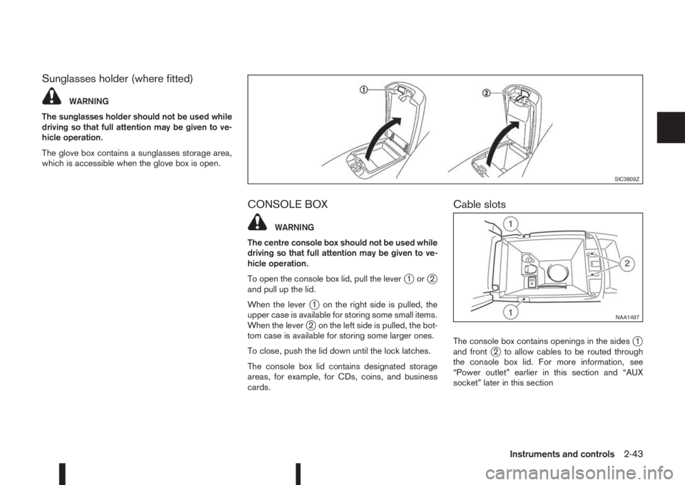
Sunglasses holder (where fitted)
WARNING
The sunglasses holder should not be used while
driving so that full attention may be given to ve-
hicle operation.
The glove box contains a sunglasses storage area,
which is accessible when the glove box is open.
CONSOLE BOX
WARNING
The centre console box should not be used while
driving so that full attention may be given to ve-
hicle operation.
To open the console box lid, pull the lever
j1orj2
and pull up the lid.
When the lever
j1 on the right side is pulled, the
upper case is available for storing some small items.
When the lever
j2 on the left side is pulled, the bot-
tom case is available for storing some larger ones.
To close, push the lid down until the lock latches.
The console box lid contains designated storage
areas, for example, for CDs, coins, and business
cards.
Cable slots
The console box contains openings in the sidesj1
and frontj2 to allow cables to be routed through
the console box lid. For more information, see
“Power outlet” earlier in this section and “AUX
socket” later in this section
SIC3809Z
NAA1497
Instruments and controls2-43
Page 102 of 338
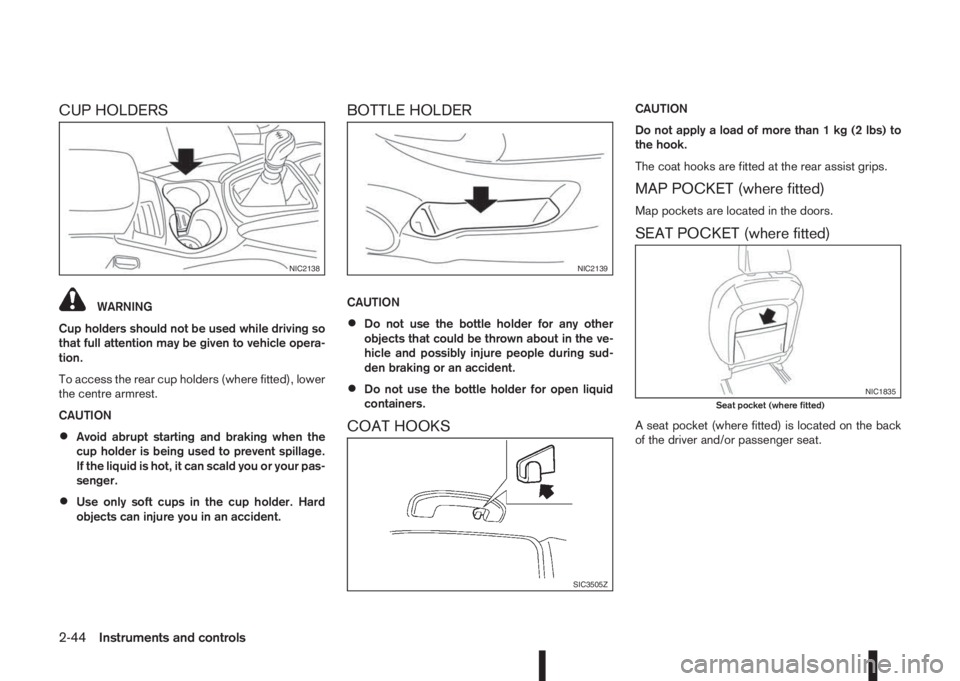
CUP HOLDERS
WARNING
Cup holders should not be used while driving so
that full attention may be given to vehicle opera-
tion.
To access the rear cup holders (where fitted), lower
the centre armrest.
CAUTION
•Avoid abrupt starting and braking when the
cup holder is being used to prevent spillage.
If the liquid is hot, it can scald you or your pas-
senger.
•Use only soft cups in the cup holder. Hard
objects can injure you in an accident.
BOTTLE HOLDER
CAUTION
•Do not use the bottle holder for any other
objects that could be thrown about in the ve-
hicle and possibly injure people during sud-
den braking or an accident.
•Do not use the bottle holder for open liquid
containers.
COAT HOOKS
CAUTION
Do not apply a load of more than 1 kg (2 lbs) to
the hook.
The coat hooks are fitted at the rear assist grips.
MAP POCKET (where fitted)
Map pockets are located in the doors.
SEAT POCKET (where fitted)
A seat pocket (where fitted) is located on the back
of the driver and/or passenger seat.
NIC2138NIC2139
SIC3505Z
NIC1835Seat pocket (where fitted)
2-44Instruments and controls
Page 103 of 338
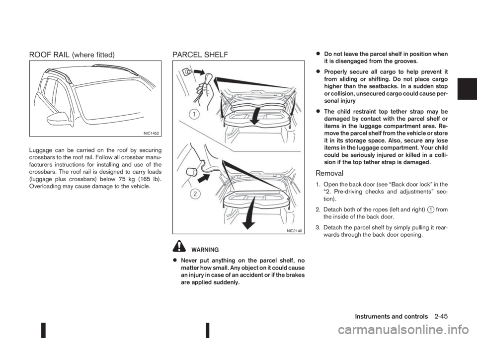
ROOF RAIL (where fitted)
Luggage can be carried on the roof by securing
crossbars to the roof rail. Follow all crossbar manu-
facturers instructions for installing and use of the
crossbars. The roof rail is designed to carry loads
(luggage plus crossbars) below 75 kg (165 lb).
Overloading may cause damage to the vehicle.
PARCEL SHELF
WARNING
•Never put anything on the parcel shelf, no
matter how small. Any object on it could cause
an injury in case of an accident or if the brakes
are applied suddenly.
•Do not leave the parcel shelf in position when
it is disengaged from the grooves.
•Properly secure all cargo to help prevent it
from sliding or shifting. Do not place cargo
higher than the seatbacks. In a sudden stop
or collision, unsecured cargo could cause per-
sonal injury
•The child restraint top tether strap may be
damaged by contact with the parcel shelf or
items in the luggage compartment area. Re-
move the parcel shelf from the vehicle or store
it in its storage space. Also, secure any lose
items in the luggage compartment. Your child
could be seriously injured or killed in a colli-
sion if the top tether strap is damaged.
Removal
1. Open the back door (see “Back door lock” in the
“2. Pre-driving checks and adjustments” sec-
tion).
2. Detach both of the ropes (left and right)
j1 from
the inside of the back door.
3. Detach the parcel shelf by simply pulling it rear-
wards through the back door opening.
NIC1452
NIC2140
Instruments and controls2-45
Page 104 of 338
CAUTION
Make sure the parcel shelf is carefully stored
when not in use in order to prevent any damage.
NOTE
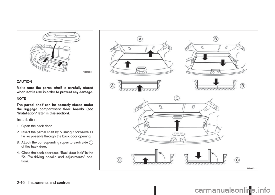
The parcel shelf can be securely stored under
the luggage compartment floor boards (see
“Installation” later in this section).
Installation
1. Open the back door.
2. Insert the parcel shelf by pushing it forwards as
far as possible through the back door opening.
3. Attach the corresponding ropes to each side
j1
of the back door.
4. Close the back door (see “Back door lock” in the
“2. Pre-driving checks and adjustments” sec-
tion).
NIC2209
NPA1312
2-46Instruments and controls
Page 105 of 338
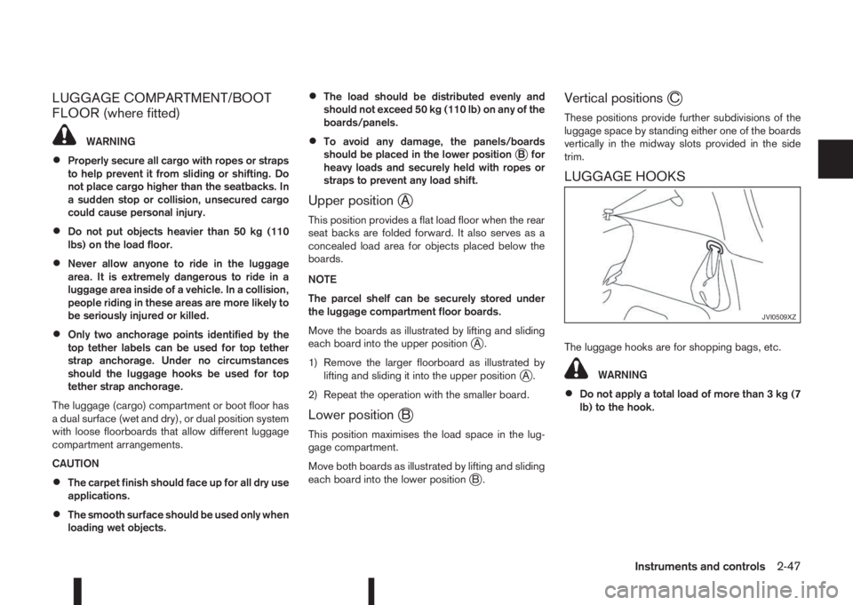
LUGGAGE COMPARTMENT/BOOT
FLOOR (where fitted)
WARNING
•Properly secure all cargo with ropes or straps
to help prevent it from sliding or shifting. Do
not place cargo higher than the seatbacks. In
a sudden stop or collision, unsecured cargo
could cause personal injury.
•Do not put objects heavier than 50 kg (110
lbs) on the load floor.
•Never allow anyone to ride in the luggage
area. It is extremely dangerous to ride in a
luggage area inside of a vehicle. In a collision,
people riding in these areas are more likely to
be seriously injured or killed.
•Only two anchorage points identified by the
top tether labels can be used for top tether
strap anchorage. Under no circumstances
should the luggage hooks be used for top
tether strap anchorage.
The luggage (cargo) compartment or boot floor has
a dual surface (wet and dry), or dual position system
with loose floorboards that allow different luggage
compartment arrangements.
CAUTION
•The carpet finish should face up for all dry use
applications.
•The smooth surface should be used only when
loading wet objects.
•The load should be distributed evenly and
should not exceed 50 kg (110 lb) on any of the
boards/panels.
•To avoid any damage, the panels/boards
should be placed in the lower positionjB for
heavy loads and securely held with ropes or
straps to prevent any load shift.
Upper positionjA
This position provides a flat load floor when the rear
seat backs are folded forward. It also serves as a
concealed load area for objects placed below the
boards.
NOTE
The parcel shelf can be securely stored under
the luggage compartment floor boards.
Move the boards as illustrated by lifting and sliding
each board into the upper position
jA.
1) Remove the larger floorboard as illustrated by
lifting and sliding it into the upper position
jA.
2) Repeat the operation with the smaller board.
Lower positionjB
This position maximises the load space in the lug-
gage compartment.
Move both boards as illustrated by lifting and sliding
each board into the lower position
jB.
Vertical positionsjC
These positions provide further subdivisions of the
luggage space by standing either one of the boards
vertically in the midway slots provided in the side
trim.
LUGGAGE HOOKS
The luggage hooks are for shopping bags, etc.
WARNING
•Do not apply a total load of more than 3 kg (7
lb) to the hook.
JVI0509XZ
Instruments and controls2-47
Page 106 of 338
POWER WINDOWS
The power window switches are located on the door
panels and will only operate when the ignition switch
is in the ON position.
WARNING
•Make sure that all passengers have their
hands, etc. inside the vehicle before operat-
ing the power windows.
•Never leave children or adults who would nor-
mally require the support of others alone in
the vehicle. They could unknowingly activate
switches or controls and inadvertently
become involved in an accident.
•It is recommended to instruct all occupants in
the safe operation of power windows with par-
ticular emphasis given to the safety and su-
pervision of children.
The power windows only operate when the ignition
switch is in the “ON” position.
To open a window, push down the power window
switch.
To close a window, pull up the power window
switch.
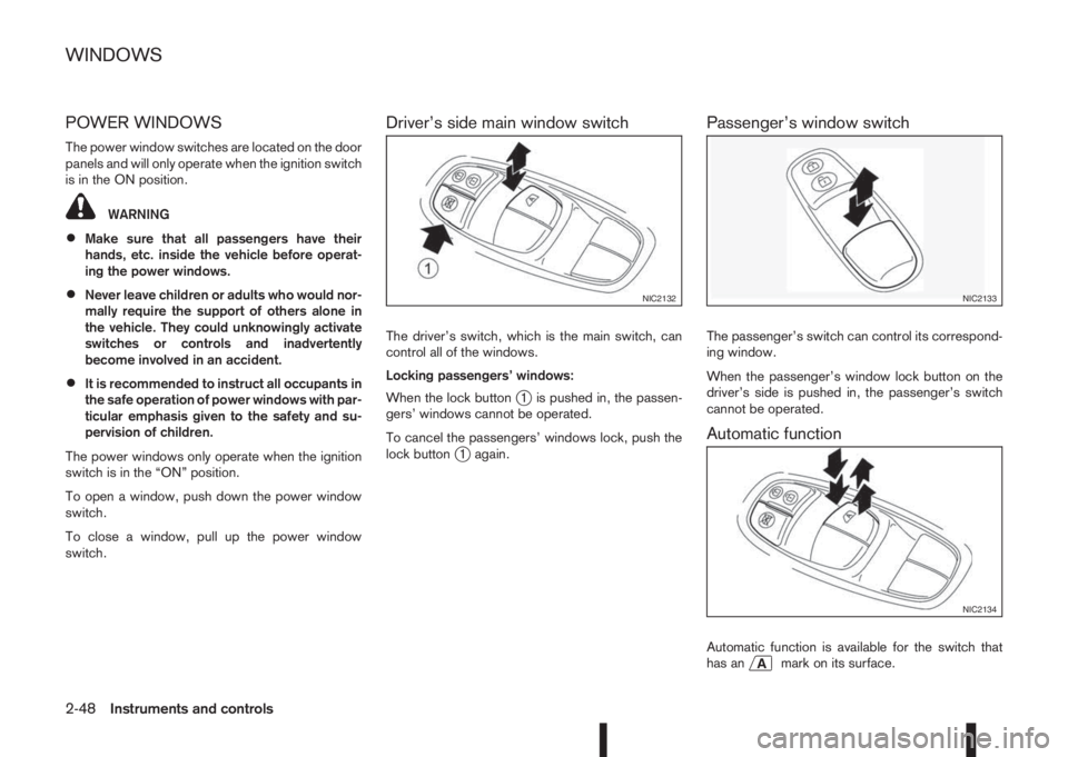
Driver’s side main window switch
The driver’s switch, which is the main switch, can
control all of the windows.
Locking passengers’ windows:
When the lock button
j1 is pushed in, the passen-
gers’ windows cannot be operated.
To cancel the passengers’ windows lock, push the
lock button
j1 again.
Passenger’s window switch
The passenger’s switch can control its correspond-
ing window.
When the passenger’s window lock button on the
driver’s side is pushed in, the passenger’s switch
cannot be operated.
Automatic function
Automatic function is available for the switch that
has anmark on its surface.
NIC2132NIC2133
NIC2134
WINDOWS
2-48Instruments and controls
Page 107 of 338
The automatic function enables a window to fully
open or close without holding the switch down or
up.
To fully open the window, push the power window
switch down to the second detent and release the
switch. To fully close the window, pull the power
window switch up to the second detent and release
the switch. The switch does not have to be held dur-
ing window operation.
To stop the window open/close operation during
the automatic function, push down or pull up the
switch in opposite direction.
Auto-reverse function:
WARNING
•There is a small distance just before the
closed position which cannot be detected.
Make sure that all passengers have their
hands, etc. inside the vehicle before closing
the windows.
•The auto-reverse function does not work
when the window is closed manually (holding
the switch in the close position).
The auto-reverse function enables a window to au-
tomatically reverse when something is caught in the
window as it is closing by the automatic function.
When the control unit detects an obstacle, the win-
dow will be lowered immediately.Depending on the environment or driving conditions,
the auto-reverse function may activate if an impact
or load similar to something being caught in the win-
dow occurs.
Reinitialisation procedure after battery
reconnection
Some power window functions (automatic close
function, auto-reverse function) will not operate as
described after the battery cable is disconnected or
the electrical supply is interrupted. Perform the fol-
lowing procedure to initialise the power window
functions.
1. Place the ignition switch in the “ON” position.
2. If the driver’s window is closed, open it com-
pletely by operating the driver’s window switch.
3. Pull up and hold the driver’s window switch to
close the driver’s window. Hold the switch for
approximately 5 seconds after the window has
been fully closed, and then release it.
4. Check if the power window functions operate
properly.
If you open or close the power window continu-
ously, it may cause the power window not to oper-
ate properly. Perform the above procedure.
If the power window functions do not operate prop-
erly after performing the above procedure, repeat
the steps. See a NISSAN dealer or qualified work-
shop, if necessary, for checking the power window
system.
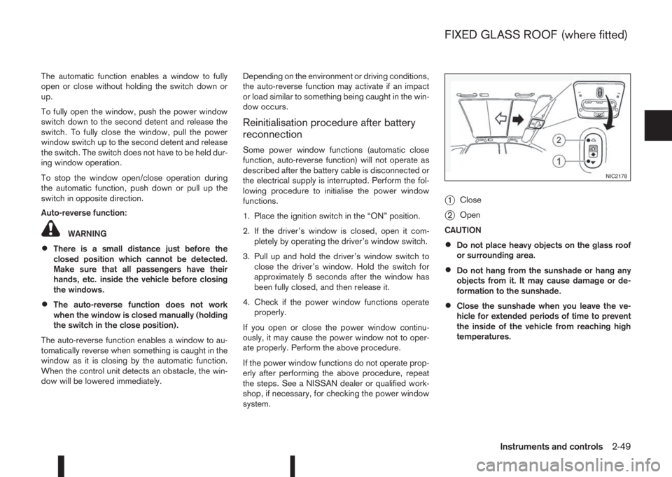
j1Close
j2Open
CAUTION
•Do not place heavy objects on the glass roof
or surrounding area.
•Do not hang from the sunshade or hang any
objects from it. It may cause damage or de-
formation to the sunshade.
•Close the sunshade when you leave the ve-
hicle for extended periods of time to prevent
the inside of the vehicle from reaching high
temperatures.
NIC2178
FIXED GLASS ROOF (where fitted)
Instruments and controls2-49
Page 108 of 338
SUNSHADE OPERATION
The sunshade operates only when the ignition switch
is in the ON position.
WARNING
Never allow hands or fingers, or any part of your
body within operating range of the sunshade. You
could be injured.
Opening and closing
Manual control:
To close the sunshade, press and hold the “CLOSE”
side of the switch
j1 To stop the sunshade from
closing fully, release the switch.
To open the sunshade press and hold the “OPEN”
side of the switch
j2 To stop the sunshade from
opening fully, release the switch.
Automatic operation:
To fully open or close the sunshade automatically,
press briefly on the open or close side of the switch
and then release. To stop the sunshade from open-
ing or closing, press either side of the switch.
Auto-reverse function:
When the control unit detects something caught in
the sunshade, the sunshade will open automatically.
NOTE
The auto-reverse function remains active
whether the sunshade is being closed manually
or automatically.CAUTION
Do not use for extended periods of time with the
engine stopped. This could discharge the bat-
tery.
NOTE
The interior lights will go off after a period of time
unless the ignition switch is in the Acc or ON
position.
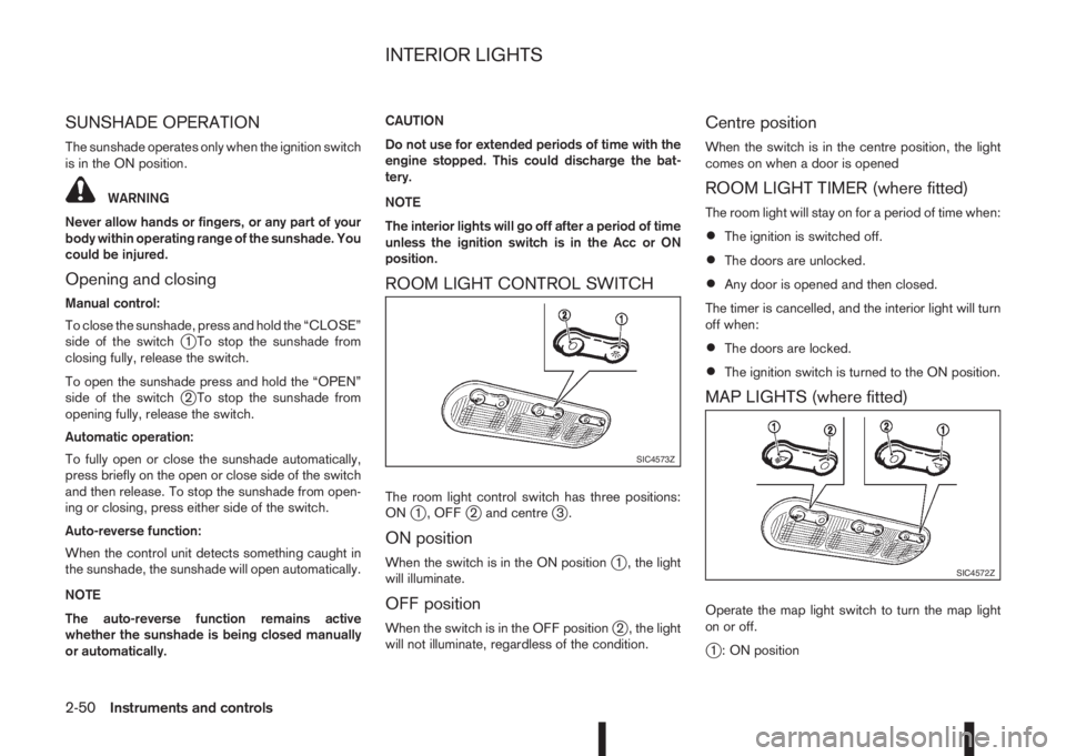
ROOM LIGHT CONTROL SWITCH
The room light control switch has three positions:
ONj1 , OFFj2 and centrej3.
ON position
When the switch is in the ON positionj1 , the light
will illuminate.
OFF position
When the switch is in the OFF positionj2 , the light
will not illuminate, regardless of the condition.
Centre position
When the switch is in the centre position, the light
comes on when a door is opened
ROOM LIGHT TIMER (where fitted)
The room light will stay on for a period of time when:
•The ignition is switched off.
•The doors are unlocked.
•Any door is opened and then closed.
The timer is cancelled, and the interior light will turn
off when:
•The doors are locked.
•The ignition switch is turned to the ON position.
MAP LIGHTS (where fitted)
Operate the map light switch to turn the map light
on or off.
j1 : ON position
SIC4573Z
SIC4572Z
INTERIOR LIGHTS
2-50Instruments and controls
Page 109 of 338
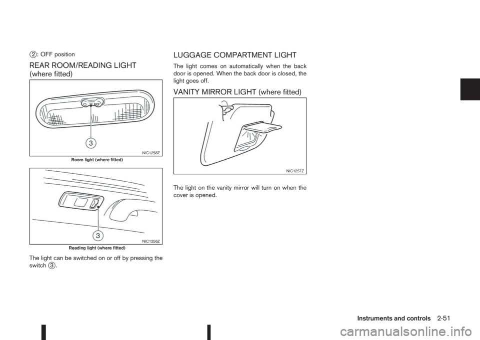
j2 : OFF position
REAR ROOM/READING LIGHT
(where fitted)
The light can be switched on or off by pressing the
switchj3.
LUGGAGE COMPARTMENT LIGHT
The light comes on automatically when the back
door is opened. When the back door is closed, the
light goes off.
VANITY MIRROR LIGHT (where fitted)
The light on the vanity mirror will turn on when the
cover is opened.
NIC1258ZRoom light (where fitted)
NIC1256ZReading light (where fitted)
NIC1257Z
Instruments and controls2-51
Page 110 of 338

NOTE
2-52Instruments and controls