NISSAN QASHQAI 2014 Owner´s Manual
Manufacturer: NISSAN, Model Year: 2014, Model line: QASHQAI, Model: NISSAN QASHQAI 2014Pages: 338, PDF Size: 4.87 MB
Page 121 of 338
–Intelligent Key models:If the Intelligent Key has
been left inside the vehicle, all doors will unlock
and an audible warning will sound.
Super Lock equipped models (RHD
models)
If the doors are locked using the integrated keyfob
lock button () or a request button (Intelligent Key
models), the Super Lock system will be activated.
The
indicator light in the centre console comes
on to indicate that all doors are locked, but it will not
be possible to use the
button of the power door
lock switch to unlock the doors.
Locking the doors with the power door lock switch
will not activate the Super Lock system.
CHILD SAFETY LOCK — REAR
DOORS
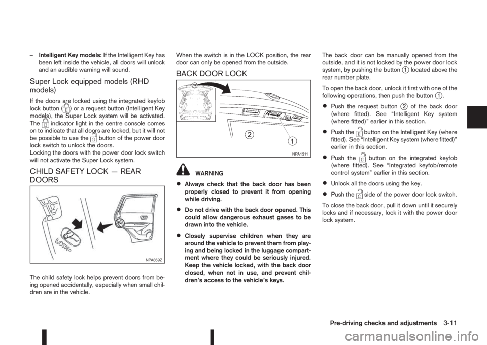
The child safety lock helps prevent doors from be-
ing opened accidentally, especially when small chil-
dren are in the vehicle.When the switch is in the LOCK position, the rear
door can only be opened from the outside.
BACK DOOR LOCK
WARNING
•Always check that the back door has been
properly closed to prevent it from opening
while driving.
•Do not drive with the back door opened. This
could allow dangerous exhaust gases to be
drawn into the vehicle.
•Closely supervise children when they are
around the vehicle to prevent them from play-
ing and being locked in the luggage compart-
ment where they could be seriously injured.
Keep the vehicle locked, with the back door
closed, when not in use, and prevent chil-
dren’s access to the vehicle’s keys.The back door can be manually opened from the
outside, and it is not locked by the power door lock
system, by pushing the button
j1 located above the
rear number plate.
To open the back door, unlock it first with one of the
following operations, then push the button
j1.
•Push the request buttonj2 of the back door
(where fitted). See “Intelligent Key system
(where fitted)” earlier in this section.
•Push thebutton on the Intelligent Key (where
fitted). See “Intelligent Key system (where fitted)”
earlier in this section.
•Push thebutton on the integrated keyfob
(where fitted). See “Integrated keyfob/remote
control system” earlier in this section.
•Unlock all the doors using the key.
•Push theside of the power door lock switch.
To close the back door, pull it down until it securely
locks and if necessary, lock it with the power door
lock system.
NPA859Z
NPA1311
Pre-driving checks and adjustments3-11
Page 122 of 338
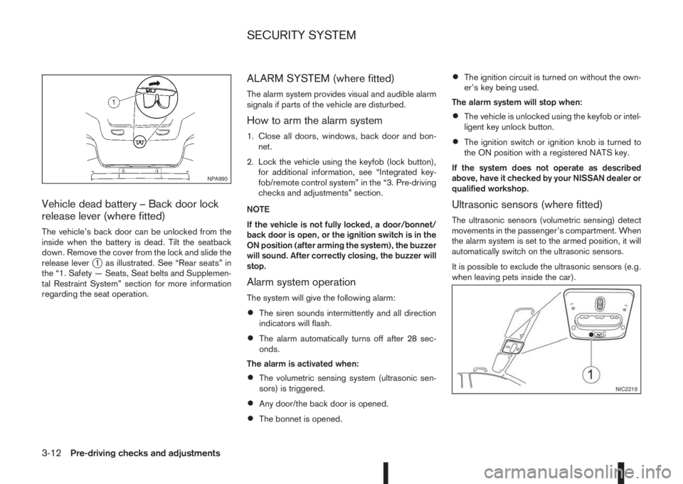
Vehicle dead battery – Back door lock
release lever (where fitted)
The vehicle’s back door can be unlocked from the
inside when the battery is dead. Tilt the seatback
down. Remove the cover from the lock and slide the
release lever
j1 as illustrated. See “Rear seats” in
the “1. Safety — Seats, Seat belts and Supplemen-
tal Restraint System” section for more information
regarding the seat operation.
ALARM SYSTEM (where fitted)
The alarm system provides visual and audible alarm
signals if parts of the vehicle are disturbed.
How to arm the alarm system
1. Close all doors, windows, back door and bon-
net.
2. Lock the vehicle using the keyfob (lock button),
for additional information, see “Integrated key-
fob/remote control system” in the “3. Pre-driving
checks and adjustments” section.
NOTE
If the vehicle is not fully locked, a door/bonnet/
back door is open, or the ignition switch is in the
ON position (after arming the system), the buzzer
will sound. After correctly closing, the buzzer will
stop.
Alarm system operation
The system will give the following alarm:
•The siren sounds intermittently and all direction
indicators will flash.
•The alarm automatically turns off after 28 sec-
onds.
The alarm is activated when:
•The volumetric sensing system (ultrasonic sen-
sors) is triggered.
•Any door/the back door is opened.
•The bonnet is opened.
•The ignition circuit is turned on without the own-
er’s key being used.
The alarm system will stop when:
•The vehicle is unlocked using the keyfob or intel-
ligent key unlock button.
•The ignition switch or ignition knob is turned to
the ON position with a registered NATS key.
If the system does not operate as described
above, have it checked by your NISSAN dealer or
qualified workshop.
Ultrasonic sensors (where fitted)
The ultrasonic sensors (volumetric sensing) detect
movements in the passenger’s compartment. When
the alarm system is set to the armed position, it will
automatically switch on the ultrasonic sensors.
It is possible to exclude the ultrasonic sensors (e.g.
when leaving pets inside the car).
NPA990
NIC2219
SECURITY SYSTEM
3-12Pre-driving checks and adjustments
Page 123 of 338
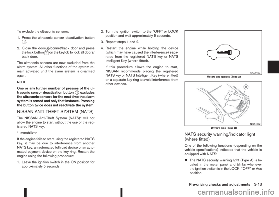
To exclude the ultrasonic sensors:
1. Press the ultrasonic sensor deactivation button
j1.
2. Close the door(s)/bonnet/back door and press
the lock button
on the keyfob to lock all doors/
back door.
The ultrasonic sensors are now excluded from the
alarm system. All other functions of the system re-
main activated until the alarm system is disarmed
again.
NOTE
One or any further number of presses of the ul-
trasonic sensor deactivation button
j1 excludes
the ultrasonic sensors for the next time the alarm
system is armed and only that instance. Pressing
the button twice does not reactivate the system.
NISSAN ANTI-THEFT SYSTEM (NATS)
The NISSAN Anti-Theft System (NATS)* will not
allow the engine to start without the use of the reg-
istered NATS key.
* Immobilizer
If the engine fails to start using the registered NATS
key, it may be due to interference from another
NATS key, an automated toll road device or an auto-
mated payment device on the key ring. Restart the
engine using the following procedure:
1. Leave the ignition switch in the ON position for
approximately 5 seconds.2. Turn the ignition switch to the “OFF” or LOCK
position and wait approximately 5 seconds.
3. Repeat steps 1 and 2.
4. Restart the engine while holding the device
(which may have caused the interference) sepa-
rated from the registered NATS key or NATS
Intelligent Key (where fitted).
If this procedure allows the engine to start,
NISSAN recommends placing the registered
NATS key or NATS Intelligent Key (where fitted)
on a separate key-ring to avoid interference from
other devices.
NATS security warning/indicator light
(where fitted)
One of the following functions (depending on the
vehicle specifications) indicates that the vehicle is
equipped with NATS:
•The NATS security warning light (Type A) is lo-
cated in the meter panel and blinks whenever
the ignition switch is in the LOCK, “OFF” or Acc
position.
SIC2045ZMeters and gauges (Type A)
NIC1402ZDriver’s side (Type B)
Pre-driving checks and adjustments3-13
Page 124 of 338
•The NATS security indicator light (TypejB) is
located on the Driver’s side of the dashboard
and blinks whenever the ignition switch is in the
LOCK, “OFF” or Acc position.
If the NISSAN Anti-Theft System (NATS) is mal-
functioning, this light will remain on while the ignition
switch is in the ON position.
If the light remains on and/or the engine will not
start, see your NISSAN dealer for NATS service
as soon as possible. Please bring all NATS keys
or NATS Intelligent Keys when visiting your
NISSAN dealer for service.
Additional information for RHD models
If the NATS is malfunctioning, this light will turn on
after flashing six times while the ignition switch is in
the ON position.
However, if the NATS security warning light turns
off after the light has remained on for 15 minutes,
there is a 10 second time slot to start the engine
after the ignition is turned off. See your NISSAN
dealer for NATS service as soon as possible.
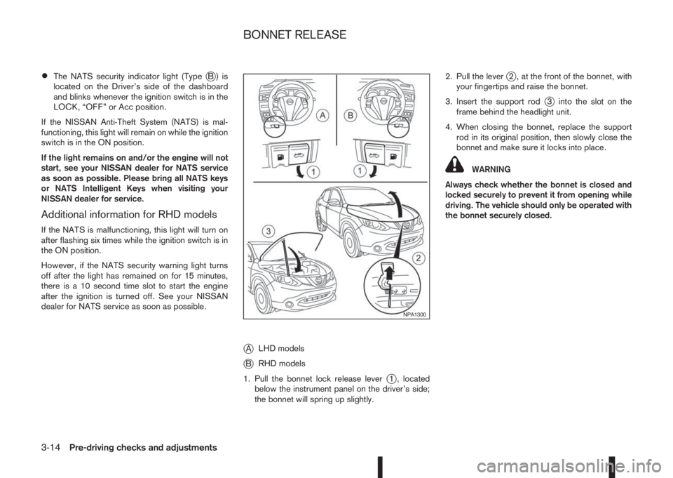
jALHD models
jBRHD models
1. Pull the bonnet lock release lever
j1 , located
below the instrument panel on the driver’s side;
the bonnet will spring up slightly.2. Pull the lever
j2 , at the front of the bonnet, with
your fingertips and raise the bonnet.
3. Insert the support rod
j3 into the slot on the
frame behind the headlight unit.
4. When closing the bonnet, replace the support
rod in its original position, then slowly close the
bonnet and make sure it locks into place.
WARNING
Always check whether the bonnet is closed and
locked securely to prevent it from opening while
driving. The vehicle should only be operated with
the bonnet securely closed.
NPA1300
BONNET RELEASE
3-14Pre-driving checks and adjustments
Page 125 of 338
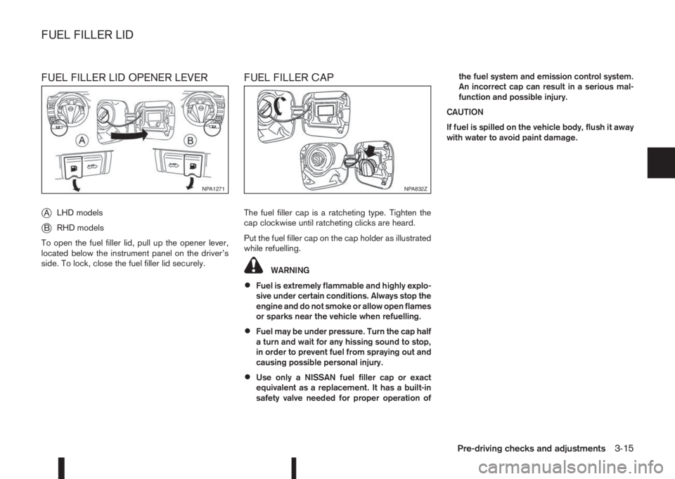
FUEL FILLER LID OPENER LEVER
j
ALHD models
jBRHD models
To open the fuel filler lid, pull up the opener lever,
located below the instrument panel on the driver’s
side. To lock, close the fuel filler lid securely.
FUEL FILLER CAP
The fuel filler cap is a ratcheting type. Tighten the
cap clockwise until ratcheting clicks are heard.
Put the fuel filler cap on the cap holder as illustrated
while refuelling.
WARNING
•Fuel is extremely flammable and highly explo-
sive under certain conditions. Always stop the
engine and do not smoke or allow open flames
or sparks near the vehicle when refuelling.
•Fuel may be under pressure. Turn the cap half
a turn and wait for any hissing sound to stop,
in order to prevent fuel from spraying out and
causing possible personal injury.
•Use only a NISSAN fuel filler cap or exact
equivalent as a replacement. It has a built-in
safety valve needed for proper operation ofthe fuel system and emission control system.
An incorrect cap can result in a serious mal-
function and possible injury.
CAUTION
If fuel is spilled on the vehicle body, flush it away
with water to avoid paint damage.
NPA1271NPA832Z
FUEL FILLER LID
Pre-driving checks and adjustments3-15
Page 126 of 338
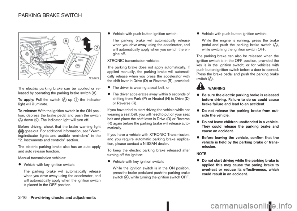
The electric parking brake can be applied or re-
leased by operating the parking brake switchjA.
To apply:Pull the switch
jAupj1 the indicator
light will illuminate.
To release:With the ignition switch in the ON posi-
tion, depress the brake pedal and push the switch
jA downj2 . The indicator light will turn off.
Before driving, check that the brake warning light
goes out. For additional information, see “Warn-
ing/indicator lights and audible reminders” in the
“2. Instruments and controls” section.
The electric parking brake also has an auto apply
and auto release function.
Manual transmission vehicles:
•Vehicle with key ignition switch:
The parking brake will automatically release
when you drive away using the accelerator, and
will automatically apply when the ignition switch
is placed in the OFF position.
•Vehicle with push-button ignition switch:
The parking brake will automatically release
when you drive away using the accelerator, and
will automatically apply when you switch the en-
gine off.
XTRONIC transmission vehicles:
The parking brake does not apply automatically. If
applied manually, the parking brake will automati-
cally release when you press the accelerator with
the shift lever in Drive (D) or Reverse (R), provided:
•The driver is wearing a seat belt, or
•The driver accelerates away within 5 seconds of
shifting from Park (P) or Neutral (N) to Drive (D)
or Reverse (R).
If you have tried to start driving the vehicle while not
wearing a seat belt, you will need to put on your seat
belt and place the shift lever in Drive (D) or Reverse
(R) again before the parking brake will release auto-
matically.
If you have a vehicle with XTRONIC Transmission,
and you require automatic parking brake applica-
tion, please contact a NISSAN dealer.
To keep the electric parking brake released after
turning off the ignition:
•Vehicle with key ignition switch:
While the ignition switch is in the ON position,
press the brake pedal and push the parking brake
switch
jA , while turning the ignition switch OFF.
•Vehicle with push-button ignition switch:
While the engine is running, press the brake
pedal and push the parking brake switch
jA,
while switching the ignition switch OFF.
The parking brake can also be released when the
ignition switch is in the OFF position, provided the
key is in the ignition switch; or for vehicles with
push-button ignition switch before a door is opened.
Press the brake pedal and push the parking brake
switch
jA.
WARNING
•Be sure the electric parking brake is released
before driving. Failure to do so could cause
brake failure and lead to an accident.
•Do not release the parking brake from out-
side the vehicle.
•Do not leave children unattended in a vehicle.
They could release the parking brake and
cause an accident.
•Before leaving the vehicle, confirm that the
vehicle is held by the parking brake or trans-
mission.
NOTE
•Do not start driving while the parking brake is
applied this may cause the paring brake to
overheat or reduce its effectiveness, which
could result in an accident.
NPA1270
PARKING BRAKE SWITCH
3-16Pre-driving checks and adjustments
Page 127 of 338
•A buzzer will sound if the vehicle is driven
without releasing the parking brake. See “Au-
dible reminders” in the “2. Instruments and
controls” section.
•While the electric parking brake is applied or
released, an operating sound is heard from
the lower side of the rear seat. This is normal
and does not indicate a malfunction.
•When the electric parking brake is frequently
applied and released in a short period of time,
the parking brake may not operate in order to
prevent the parking brake system from over-
heating. If this occurs, operate the electric
parking brake switch again after waiting ap-
proximately 1 minute.
•The electric parking brake can only be re-
leased with the ignition switch in the ON posi-
tion.
•If the electric parking brake must be applied
while driving in an emergency, pull up and
hold the parking brake switch. When you re-
lease the parking brake switch, the parking
brake will be released.
•While pulling up the electric parking brake
switch while driving, the parking brake is ap-
plied and a chime sounds. The parking brake
indicator light in the meter and in the parking
brake switch illuminate. This does not indi-
cate a malfunction. The electric parking brake
indicator lights in the meter and in the parking
brake switch turn off when the parking brake
is released.
•Pull up the electric parking brake switch twice
so that the maximum electric parking brake
force is applied to the vehicle.
•When pulling the electric parking brake switch
up with the ignition switch in the OFF or ACC
position, the parking brake switch indicator
light will continue to illuminate for a short pe-
riod of time.
CAUTION
To park the vehicle in cold climates place the
shift lever in 1st (1) or Reverse (R) (or in Park (P)
for automatic (AT) vehicles), and place suitable
chocks at both the front and back of a wheel with
the electric parking brake released. If the electric
parking brake is applied in cold climates, the
brake may become frozen and cannot be re-
leased.
DRIVING AWAY WHEN TOWING A
TRAILER
Please note the following points to prevent the ve-
hicle from rolling back unintentionally on a gradient.
•Pull and hold the parking brake switch and press
the accelerator. The parking brake will remain
engaged and prevent any tendency to roll back
down the slope.
•You can release the parking brake switch as
soon as the engine is delivering enough power
to the wheels.
Depending on the weight of the vehicle and trailer
and the steepness of the slope, there may be a ten-dency to roll back downhill when driving away from
a standstill. You can prevent this by pulling up the
parking brake switch as you press the accelerator
(in the same way as with a conventional handbrake).
Pre-driving checks and adjustments3-17
Page 128 of 338
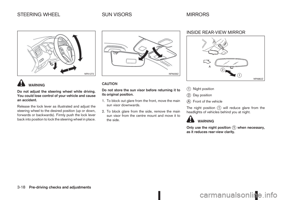
WARNING
Do not adjust the steering wheel while driving.
You could lose control of your vehicle and cause
an accident.
Release the lock lever as illustrated and adjust the
steering wheel to the desired position (up or down,
forwards or backwards). Firmly push the lock lever
back into position to lock the steering wheel in place.CAUTION
Do not store the sun visor before returning it to
its original position.
1. To block out glare from the front, move the main
sun visor downwards.
2. To block glare from the side, remove the main
sun visor from the centre mount and move it to
the side.
INSIDE REAR-VIEW MIRROR
j
1Night position
j2Day position
jAFront of the vehicle
The night position
j1 will reduce glare from the
headlights of vehicles behind you at night.
WARNING
Only use the night position
j1 when necessary,
as it reduces rear-view clarity.
NPA1272NPA839Z
NPA862Z
STEERING WHEEL SUN VISORS MIRRORS
3-18Pre-driving checks and adjustments
Page 129 of 338
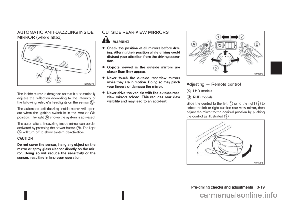
AUTOMATIC ANTI-DAZZLING INSIDE
MIRROR (where fitted)
The inside mirror is designed so that it automatically
adjusts the reflection according to the intensity of
the following vehicle’s headlights on the sensor
jC.
The automatic anti-dazzling inside mirror will oper-
ate when the ignition switch is in the Acc or ON
position. The light
jA shows the system is activated.
The automatic anti-dazzling inside mirror can be de-
activated by pressing the power button
jB . The lightjA will turn off to show system deactivation.
CAUTION
Do not cover the sensor, hang any object on the
mirror or spray glass cleaner directly on the mir-
ror. Doing so will reduce the sensitivity of the
sensor, resulting in improper operation.
OUTSIDE REAR-VIEW MIRRORS
WARNING
•Check the position of all mirrors before driv-
ing. Altering their position while driving could
distract your attention from the driving opera-
tion.
•Objects viewed in the outside mirrors are
closer than they appear.
•Never touch the outside rear-view mirrors
while they are in motion. Doing so may pinch
your fingers or damage the mirror.
•Never drive the vehicle with the outside rear-
view mirrors folded. This reduces rear view
visibility and may lead to an accident.
Adjusting — Remote control
j
ALHD models
jBRHD models
Slide the control to the left
j1 or to the rightj2to
select the left or right outside rear-view mirror, then
adjust the mirror to the desired position by pushing
the control as illustrated
j3.
NPA1273
NPA1276
NPA1278
Pre-driving checks and adjustments3-19
Page 130 of 338
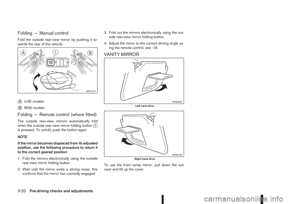
Folding — Manual control
Fold the outside rear-view mirror by pushing it to-
wards the rear of the vehicle.
jALHD models
jBRHD models
Folding — Remote control (where fitted)
The outside rear-view mirrors automatically fold
when the outside rear-view mirror folding buttonj1
is pressed. To unfold, push the button again.
NOTE
If the mirror becomes displaced from its adjusted
position, use the following procedure to return it
to the correct geared position:
1. Fold the mirrors electronically using the outside
rear-view mirror folding button.
2. Wait until the mirror emits a strong noise, this
confirms that the mirror has correctly engaged.3. Fold out the mirrors electronically using the out-
side rear-view mirror folding button.
4. Adjust the mirror to the correct driving angle us-
ing the remote control, see -19.
VANITY MIRROR
To use the front vanity mirror, pull down the sun
visor and lift up the cover.
NPA1277
NPA842ZLeft hand drive
NPA910ZRight hand drive
3-20Pre-driving checks and adjustments