sensor NISSAN QASHQAI 2016 OwnerôÇs Manual
[x] Cancel search | Manufacturer: NISSAN, Model Year: 2016, Model line: QASHQAI, Model: NISSAN QASHQAI 2016Pages: 338, PDF Size: 4.87 MB
Page 90 of 338
WARNING
In freezing temperatures the washer fluid may
freeze on the windscreen and obscure your vi-
sion. Warm the windscreen with the defogger be-
fore you wash it.
CAUTION
ãÂDo not open/release the bonnet when the
front wiper arms are raised from their original
position.
ãÂDo not operate the washer continuously for
more than 15 seconds.
ãÂDo not operate the washer if the reservoir
tank is empty or frozen.
WINDSCREEN
The windscreen wiper and washer can be operated
when the ignition switch is in the ON position.
Wiper operation
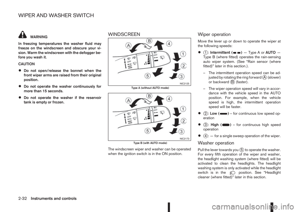
Move the lever up or down to operate the wiper at
the following speeds:
ãÂj1:Intermittent ()ãTypeAorAUTOã
Type B (where fitted) operates the rain-sensing
auto wiper system. (See ãRain sensor (where
fitted)ã later in this section.).
ã The intermittent operation speed can be ad-
justed by rotating the ring forward
jA (slower)
or backwardjB (faster).
ã The wiper operation speed will vary in accor-
dance with the vehicle speed in the AUTO
position. For example, when the vehicle
speed is high, the intermittent operation
speed will be faster.
ãÂj2:Low ()ã for continuous low speed op-
eration
ãÂj3:High ()ã for continuous high speed
operation
ãÂj4 : ã for a single sweep operation of the wiper.
Washer operation
Pull the lever towards youj5 to operate the washer.
For every fifth operation of the wiper and washer,
the headlight washing system (where fitted) will be
activated to clean the headlights. The headlight
washing system is only activated while the headlight
switch is in the
position. See ãHeadlight
cleaner (where fitted)ã later in this section.
NIC2125Type A (without AUTO mode)
NIC2173Type B (with AUTO mode)
WIPER AND WASHER SWITCH
2-32Instruments and controls
Page 91 of 338
Wiper drip wipe system (where fitted):
The wiper will also operate once about 3 seconds
after using the washer. This operation is to wipe
washer fluid that has dripped on the windscreen.
Rain sensor (where fitted)
The sensor of the rain-sensing auto wiper system
located on the upper part of the windscreen, in front
of the rear view mirror, can automatically turn on the
wipers and adjust the wiper speed depending on
the rainfall intensity and the vehicle speed when the
lever in the AUTO position
j1.
The sensitivity can be adjusted by rotating the ring
of the wiper switch forward
jA ã less sensitive, or
backwardjB ã more sensitive.
NOTE
ãÂBe sure to turn off the rain-sensing auto wiper
system when the car is in the car wash.
ãÂLeaving the lever in AUTO position will not
harm the rain sensor system, although occa-
sional unexpected activation of the wipers
may occur.
ãÂIf the switch is left in the AUTO position, the
wipers may operate unexpectedly when dirt,
fingerprints, oil film or insects are covering
the windscreen of the rain sensor location.
The wipers may also operate when exhaust
gas or moisture affects the rain sensor.
ãÂDo not touch or cover the windscreen where
the rain sensor is located. The wipers may
operate unexpectedly when the wiper switchis in the AUTO position and the ignition switch
is in the ON position. This can cause an injury
or a wiper damage.
REAR WINDOW
WARNING
In freezing temperatures the washer solution
may freeze on the rear window and obscure your
vision. Warm the rear window with the rear win-
dow defogger before using the rear wipers.
CAUTION
ãÂDo not operate the washer continuously for
more than 15 seconds.
ãÂDo not operate the washer if the reservoir
tank is empty or frozen.
The rear window wiper and washer operates when
the ignition switch is in the ON position.
Wiper operation
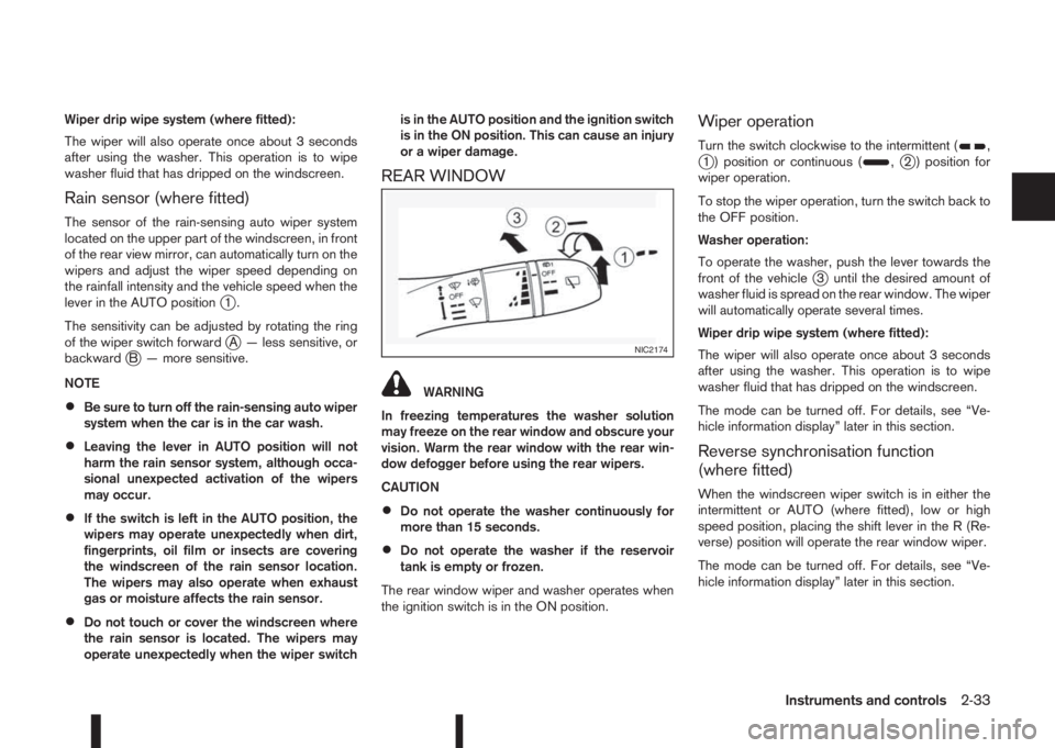
Turn the switch clockwise to the intermittent (,j1 ) position or continuous (,j2 ) position for
wiper operation.
To stop the wiper operation, turn the switch back to
the OFF position.
Washer operation:
To operate the washer, push the lever towards the
front of the vehicle
j3 until the desired amount of
washer fluid is spread on the rear window. The wiper
will automatically operate several times.
Wiper drip wipe system (where fitted):
The wiper will also operate once about 3 seconds
after using the washer. This operation is to wipe
washer fluid that has dripped on the windscreen.
The mode can be turned off. For details, see ãVe-
hicle information displayã later in this section.
Reverse synchronisation function
(where fitted)
When the windscreen wiper switch is in either the
intermittent or AUTO (where fitted), low or high
speed position, placing the shift lever in the R (Re-
verse) position will operate the rear window wiper.
The mode can be turned off. For details, see ãVe-
hicle information displayã later in this section.
NIC2174
Instruments and controls2-33
Page 95 of 338
DYNAMIC HIGH BEAM ASSISTANT
(where fitted)
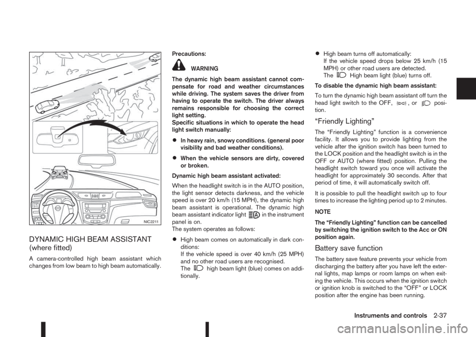
A camera-controlled high beam assistant which
changes from low beam to high beam automatically.Precautions:
WARNING
The dynamic high beam assistant cannot com-
pensate for road and weather circumstances
while driving. The system saves the driver from
having to operate the switch. The driver always
remains responsible for choosing the correct
light setting.
Specific situations in which to operate the head
light switch manually:
ãÂIn heavy rain, snowy conditions. (general poor
visibility and bad weather conditions).
ãÂWhen the vehicle sensors are dirty, covered
or broken.
Dynamic high beam assistant activated:
When the headlight switch is in the AUTO position,
the light sensor detects darkness, and the vehicle
speed is over 20 km/h (15 MPH), the dynamic high
beam assistant is operational. The dynamic high
beam assistant indicator light
in the instrument
panel is on.
The system operates as follows:
ãÂHigh beam comes on automatically in dark con-
ditions:
If the vehicle speed is over 40 km/h (25 MPH)
and no other road users are recognised.
The
high beam light (blue) comes on addi-
tionally.
ãÂHigh beam turns off automatically:
If the vehicle speed drops below 25 km/h (15
MPH) or other road users are detected.
The
High beam light (blue) turns off.
To disable the dynamic high beam assistant:
To turn the dynamic high beam assistant off turn the
head light switch to the OFF,
,orposi-
tion.
ãFriendly Lightingã
The ãFriendly Lightingã function is a convenience
facility. It allows you to provide lighting from the
vehicle after the ignition switch has been turned to
the LOCK position and the headlight switch is in the
OFF or AUTO (where fitted) position. Pulling the
headlight switch toward you once will activate the
headlight for approximately 30 seconds. After that
period of time, it will automatically switch off.
It is possible to pull the headlight switch up to four
times to increase the lighting period up to 2 minutes.
NOTE
The ãFriendly Lightingã function can be cancelled
by switching the ignition switch to the Acc or ON
position again.
Battery save function
The battery save feature prevents your vehicle from
discharging the battery after you have left the exter-
nal lights, map lamps or room lamps on when exit-
ing the vehicle. This occurs when the ignition switch
or ignition knob is switched to the ãOFFã or LOCK
position after the engine has been running.
NIC2211
Instruments and controls2-37
Page 122 of 338
Vehicle dead battery ã Back door lock
release lever (where fitted)
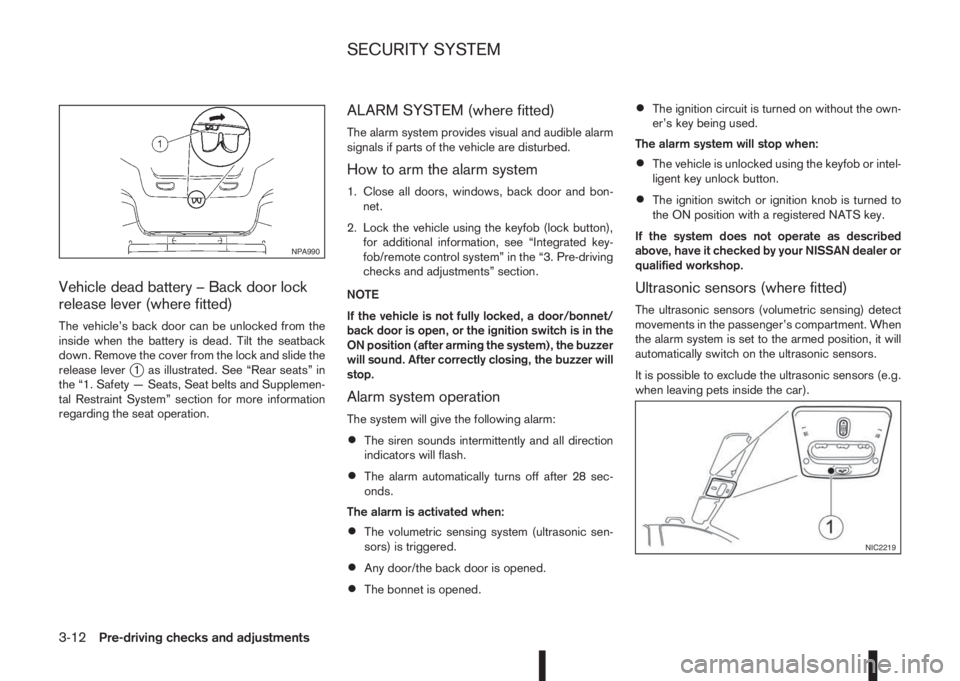
The vehicleãs back door can be unlocked from the
inside when the battery is dead. Tilt the seatback
down. Remove the cover from the lock and slide the
release lever
j1 as illustrated. See ãRear seatsã in
the ã1. Safety ã Seats, Seat belts and Supplemen-
tal Restraint Systemã section for more information
regarding the seat operation.
ALARM SYSTEM (where fitted)
The alarm system provides visual and audible alarm
signals if parts of the vehicle are disturbed.
How to arm the alarm system
1. Close all doors, windows, back door and bon-
net.
2. Lock the vehicle using the keyfob (lock button),
for additional information, see ãIntegrated key-
fob/remote control systemã in the ã3. Pre-driving
checks and adjustmentsã section.
NOTE
If the vehicle is not fully locked, a door/bonnet/
back door is open, or the ignition switch is in the
ON position (after arming the system), the buzzer
will sound. After correctly closing, the buzzer will
stop.
Alarm system operation
The system will give the following alarm:
ãÂThe siren sounds intermittently and all direction
indicators will flash.
ãÂThe alarm automatically turns off after 28 sec-
onds.
The alarm is activated when:
ãÂThe volumetric sensing system (ultrasonic sen-
sors) is triggered.
ãÂAny door/the back door is opened.
ãÂThe bonnet is opened.
ãÂThe ignition circuit is turned on without the own-
erãs key being used.
The alarm system will stop when:
ãÂThe vehicle is unlocked using the keyfob or intel-
ligent key unlock button.
ãÂThe ignition switch or ignition knob is turned to
the ON position with a registered NATS key.
If the system does not operate as described
above, have it checked by your NISSAN dealer or
qualified workshop.
Ultrasonic sensors (where fitted)
The ultrasonic sensors (volumetric sensing) detect
movements in the passengerãs compartment. When
the alarm system is set to the armed position, it will
automatically switch on the ultrasonic sensors.
It is possible to exclude the ultrasonic sensors (e.g.
when leaving pets inside the car).
NPA990
NIC2219
SECURITY SYSTEM
3-12Pre-driving checks and adjustments
Page 123 of 338
To exclude the ultrasonic sensors:
1. Press the ultrasonic sensor deactivation button
j1.
2. Close the door(s)/bonnet/back door and press
the lock button
on the keyfob to lock all doors/
back door.
The ultrasonic sensors are now excluded from the
alarm system. All other functions of the system re-
main activated until the alarm system is disarmed
again.
NOTE
One or any further number of presses of the ul-
trasonic sensor deactivation button
j1 excludes
the ultrasonic sensors for the next time the alarm
system is armed and only that instance. Pressing
the button twice does not reactivate the system.
NISSAN ANTI-THEFT SYSTEM (NATS)
The NISSAN Anti-Theft System (NATS)* will not
allow the engine to start without the use of the reg-
istered NATS key.
* Immobilizer
If the engine fails to start using the registered NATS
key, it may be due to interference from another
NATS key, an automated toll road device or an auto-
mated payment device on the key ring. Restart the
engine using the following procedure:
1. Leave the ignition switch in the ON position for
approximately 5 seconds.2. Turn the ignition switch to the ãOFFã or LOCK
position and wait approximately 5 seconds.
3. Repeat steps 1 and 2.
4. Restart the engine while holding the device
(which may have caused the interference) sepa-
rated from the registered NATS key or NATS
Intelligent Key (where fitted).
If this procedure allows the engine to start,
NISSAN recommends placing the registered
NATS key or NATS Intelligent Key (where fitted)
on a separate key-ring to avoid interference from
other devices.
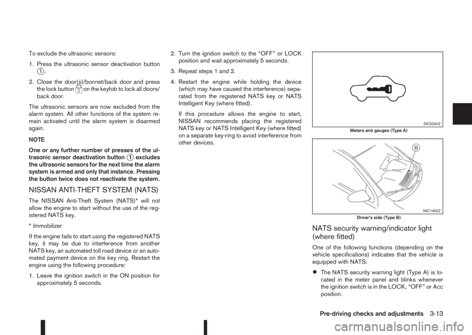
NATS security warning/indicator light
(where fitted)
One of the following functions (depending on the
vehicle specifications) indicates that the vehicle is
equipped with NATS:
ãÂThe NATS security warning light (Type A) is lo-
cated in the meter panel and blinks whenever
the ignition switch is in the LOCK, ãOFFã or Acc
position.
SIC2045ZMeters and gauges (Type A)
NIC1402ZDriverãs side (Type B)
Pre-driving checks and adjustments3-13
Page 129 of 338
AUTOMATIC ANTI-DAZZLING INSIDE
MIRROR (where fitted)
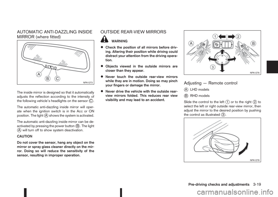
The inside mirror is designed so that it automatically
adjusts the reflection according to the intensity of
the following vehicleãs headlights on the sensor
jC.
The automatic anti-dazzling inside mirror will oper-
ate when the ignition switch is in the Acc or ON
position. The light
jA shows the system is activated.
The automatic anti-dazzling inside mirror can be de-
activated by pressing the power button
jB . The lightjA will turn off to show system deactivation.
CAUTION
Do not cover the sensor, hang any object on the
mirror or spray glass cleaner directly on the mir-
ror. Doing so will reduce the sensitivity of the
sensor, resulting in improper operation.
OUTSIDE REAR-VIEW MIRRORS
WARNING
ãÂCheck the position of all mirrors before driv-
ing. Altering their position while driving could
distract your attention from the driving opera-
tion.
ãÂObjects viewed in the outside mirrors are
closer than they appear.
ãÂNever touch the outside rear-view mirrors
while they are in motion. Doing so may pinch
your fingers or damage the mirror.
ãÂNever drive the vehicle with the outside rear-
view mirrors folded. This reduces rear view
visibility and may lead to an accident.
Adjusting ã Remote control
j
ALHD models
jBRHD models
Slide the control to the left
j1 or to the rightj2to
select the left or right outside rear-view mirror, then
adjust the mirror to the desired position by pushing
the control as illustrated
j3.
NPA1273
NPA1276
NPA1278
Pre-driving checks and adjustments3-19
Page 134 of 338
ãÂDo not damage the transparent camera cover as
the NissanConnect display may be adversely af-
fected.
ãÂDo not use body wax on the transparent camera
cover. Wipe off any wax with a clean cloth damp-
ened with mild detergent diluted with water.
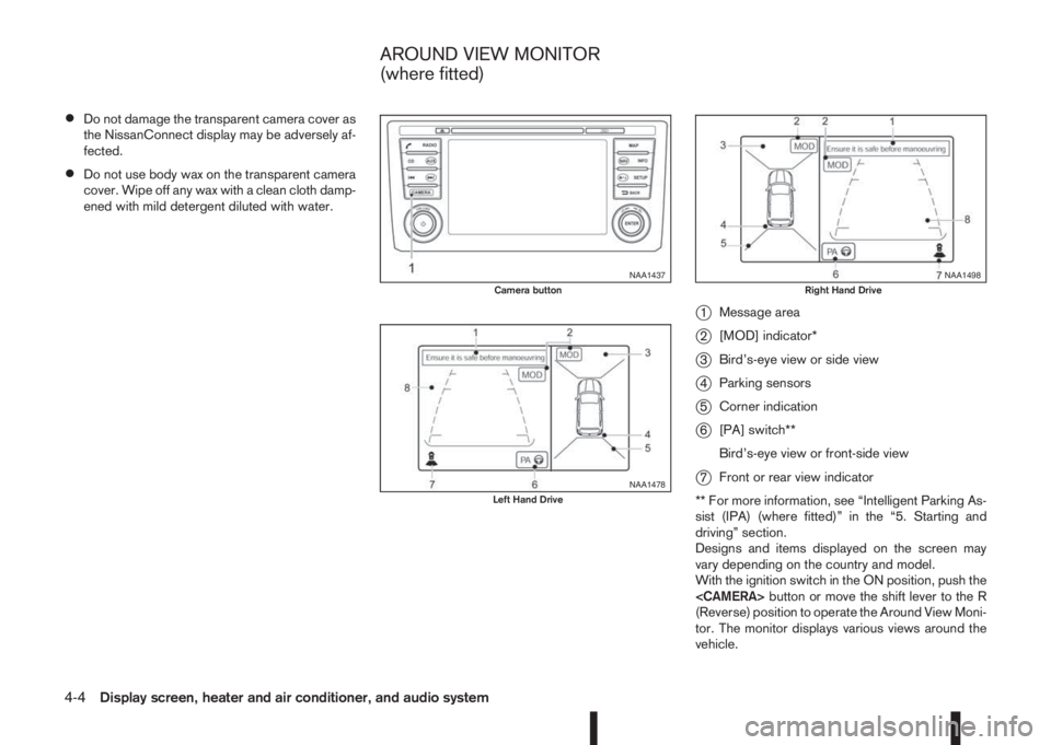
j1Message area
j2[MOD] indicator*
j3Birdãs-eye view or side view
j4Parking sensors
j5Corner indication
j6[PA] switch**
Birdãs-eye view or front-side view
j7Front or rear view indicator
** For more information, see ãIntelligent Parking As-
sist (IPA) (where fitted)ã in the ã5. Starting and
drivingã section.
Designs and items displayed on the screen may
vary depending on the country and model.
With the ignition switch in the ON position, push the
(Reverse) position to operate the Around View Moni-
tor. The monitor displays various views around the
vehicle.
NAA1437Camera button
NAA1478Left Hand Drive
NAA1498Right Hand Drive
AROUND VIEW MONITOR
(where fitted)
4-4Display screen, heater and air conditioner, and audio system
Page 137 of 338
OPERATION
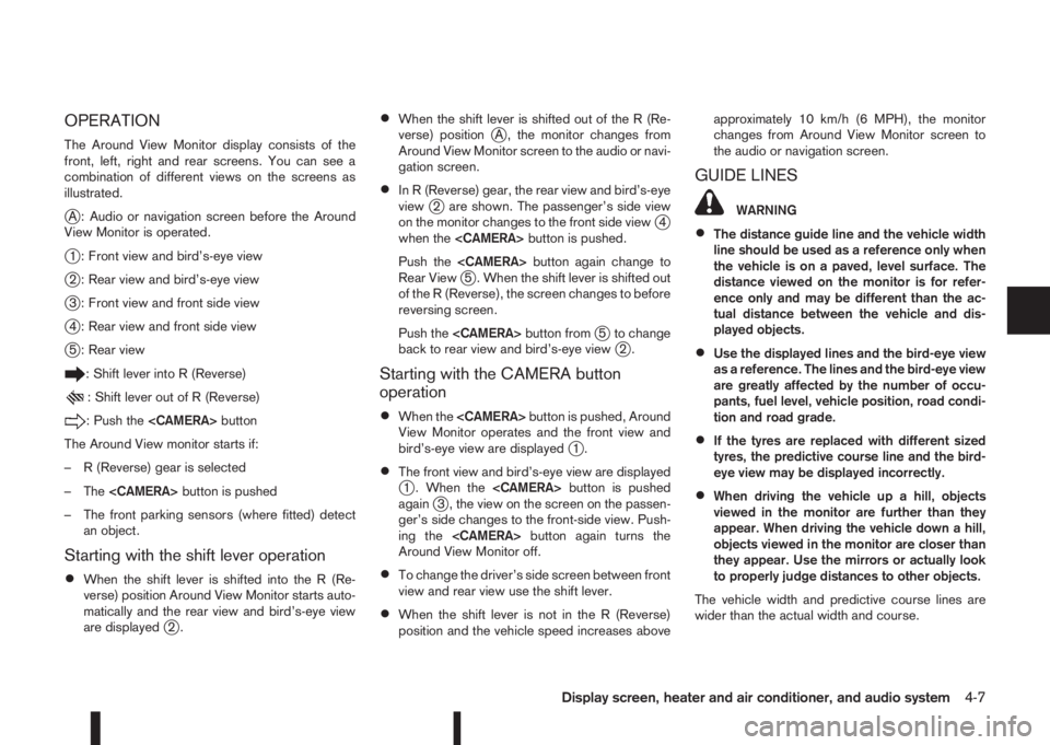
The Around View Monitor display consists of the
front, left, right and rear screens. You can see a
combination of different views on the screens as
illustrated.
jA : Audio or navigation screen before the Around
View Monitor is operated.
j1 : Front view and birdãs-eye view
j2 : Rear view and birdãs-eye view
j3 : Front view and front side view
j4 : Rear view and front side view
j5 : Rear view
: Shift lever into R (Reverse)
: Shift lever out of R (Reverse)
: Push the
The Around View monitor starts if:
ã R (Reverse) gear is selected
ã The
ã The front parking sensors (where fitted) detect
an object.
Starting with the shift lever operation
ãÂWhen the shift lever is shifted into the R (Re-
verse) position Around View Monitor starts auto-
matically and the rear view and birdãs-eye view
are displayed
j2.
ãÂWhen the shift lever is shifted out of the R (Re-
verse) positionjA , the monitor changes from
Around View Monitor screen to the audio or navi-
gation screen.
ãÂIn R (Reverse) gear, the rear view and birdãs-eye
viewj2 are shown. The passengerãs side view
on the monitor changes to the front side viewj4
when the
Push the
Rear View
j5 . When the shift lever is shifted out
of the R (Reverse), the screen changes to before
reversing screen.
Push the
j5 to change
back to rear view and birdãs-eye viewj2.
Starting with the CAMERA button
operation
ãÂWhen the
View Monitor operates and the front view and
birdãs-eye view are displayed
j1.
ãÂThe front view and birdãs-eye view are displayedj1 . When the
againj3 , the view on the screen on the passen-
gerãs side changes to the front-side view. Push-
ing the
Around View Monitor off.
ãÂTo change the driverãs side screen between front
view and rear view use the shift lever.
ãÂWhen the shift lever is not in the R (Reverse)
position and the vehicle speed increases aboveapproximately 10 km/h (6 MPH), the monitor
changes from Around View Monitor screen to
the audio or navigation screen.
GUIDE LINES
WARNING
ãÂThe distance guide line and the vehicle width
line should be used as a reference only when
the vehicle is on a paved, level surface. The
distance viewed on the monitor is for refer-
ence only and may be different than the ac-
tual distance between the vehicle and dis-
played objects.
ãÂUse the displayed lines and the bird-eye view
as a reference. The lines and the bird-eye view
are greatly affected by the number of occu-
pants, fuel level, vehicle position, road condi-
tion and road grade.
ãÂIf the tyres are replaced with different sized
tyres, the predictive course line and the bird-
eye view may be displayed incorrectly.
ãÂWhen driving the vehicle up a hill, objects
viewed in the monitor are further than they
appear. When driving the vehicle down a hill,
objects viewed in the monitor are closer than
they appear. Use the mirrors or actually look
to properly judge distances to other objects.
The vehicle width and predictive course lines are
wider than the actual width and course.
Display screen, heater and air conditioner, and audio system4-7
Page 139 of 338
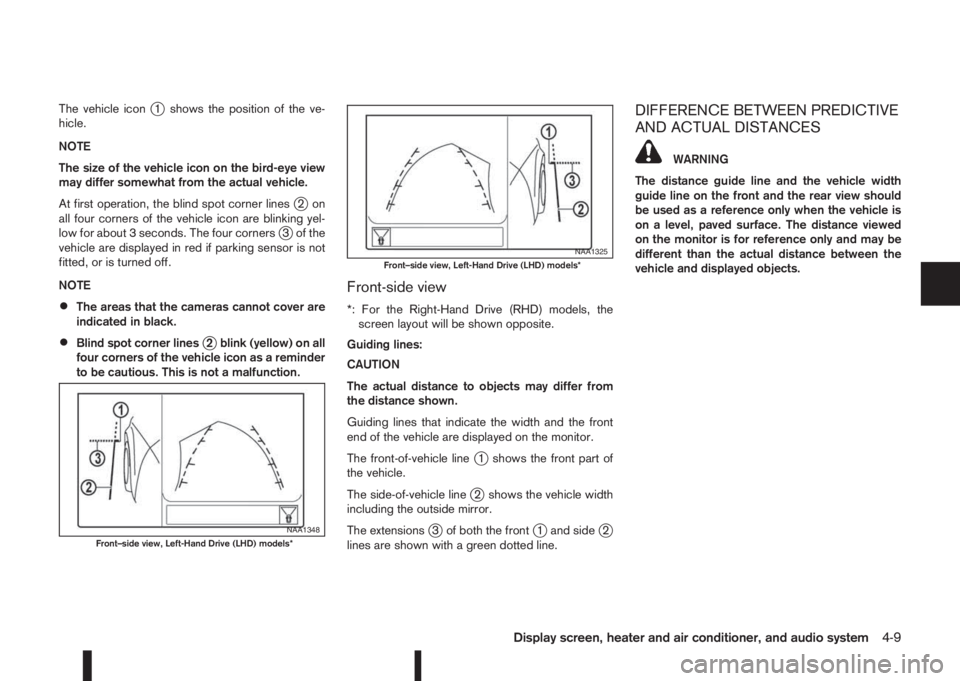
The vehicle iconj1 shows the position of the ve-
hicle.
NOTE
The size of the vehicle icon on the bird-eye view
may differ somewhat from the actual vehicle.
At first operation, the blind spot corner lines
j2on
all four corners of the vehicle icon are blinking yel-
low for about 3 seconds. The four corners
j3 of the
vehicle are displayed in red if parking sensor is not
fitted, or is turned off.
NOTE
ãÂThe areas that the cameras cannot cover are
indicated in black.
ãÂBlind spot corner linesj2 blink (yellow) on all
four corners of the vehicle icon as a reminder
to be cautious. This is not a malfunction.
Front-side view
*: For the Right-Hand Drive (RHD) models, the
screen layout will be shown opposite.
Guiding lines:
CAUTION
The actual distance to objects may differ from
the distance shown.
Guiding lines that indicate the width and the front
end of the vehicle are displayed on the monitor.
The front-of-vehicle line
j1 shows the front part of
the vehicle.
The side-of-vehicle line
j2 shows the vehicle width
including the outside mirror.
The extensions
j3 of both the frontj1 and sidej2
lines are shown with a green dotted line.
DIFFERENCE BETWEEN PREDICTIVE
AND ACTUAL DISTANCES
WARNING
The distance guide line and the vehicle width
guide line on the front and the rear view should
be used as a reference only when the vehicle is
on a level, paved surface. The distance viewed
on the monitor is for reference only and may be
different than the actual distance between the
vehicle and displayed objects.
NAA1348Frontãside view, Left-Hand Drive (LHD) models*
NAA1325Frontãside view, Left-Hand Drive (LHD) models*
Display screen, heater and air conditioner, and audio system4-9
Page 176 of 338
5Starting and drivingStarting and driving
Running-in schedule ................................................ 5-2
Before starting the engine ........................................ 5-2
Precautions when starting and driving ...................... 5-3
Exhaust gas (Carbon Monoxide) ......................... 5-3
Tyre Pressure Monitoring System (TPMS)................ 5-4
Meter information................................................ 5-7
Activation............................................................ 5-7
TPMS sensor ID and position recognition ........... 5-7
Adjusting TPMS target pressure ......................... 5-8
Tyre pressure units ............................................. 5-8
[Check cold tyre] message ................................. 5-8
TPMS temperature calibration............................. 5-8
On-pavement and off-road driving precautions ......... 5-9
Three-way catalyst (Petrol engine models)................ 5-9
To help prevent damage ..................................... 5-9
Turbocharger system (Diesel engine models) ........... 5-10
Care when driving ................................................... 5-10
Engine cold start period ...................................... 5-10
Loading luggage ................................................. 5-10
Driving on wet roads ........................................... 5-10
Driving under winter conditions ........................... 5-10
Ignition switch (where fitted) .................................... 5-11
Manual transmission ........................................... 5-11
XTRONIC transmission (CVT) ............................ 5-11
Steering lock ...................................................... 5-11
Key positions ...................................................... 5-11
NISSAN Anti-Theft System (NATS) (where
fitted).................................................................. 5-12
Push-button ignition switch (where fitted) ................. 5-12Precautions on push-button ignition switch
operation ............................................................ 5-12
Intelligent Key system ......................................... 5-12
Ignition switch positions ...................................... 5-13
Emergency engine shut off.................................. 5-14
Steering lock ...................................................... 5-14
Intelligent Key battery discharge.......................... 5-14
Starting engine ........................................................ 5-15
Models with Intelligent Key system ...................... 5-15
Models without Intelligent Key system ................. 5-16
Driving the vehicle.................................................... 5-17
Driving with manual transmission......................... 5-17
Driving with XTRONIC Transmission (CVT) ........ 5-18
Stop/Start System (where fitted) .............................. 5-22
Normal operation ................................................ 5-22
Precautions ........................................................ 5-24
Stop/Start System OFF switch ........................... 5-25
Environmental savings ........................................ 5-25
Four-wheel Drive (4WD) (where fitted)..................... 5-26
4WD mode operations........................................ 5-27
4WD shift tips .................................................... 5-27
4WD Mode indicator lights ................................. 5-28
Driving four-wheel drive (4WD) safely ................. 5-28
Blind Spot Warning (BSW) system (where fitted)..... 5-30
BSW system operation ....................................... 5-30
BSW driving situations ....................................... 5-32
BSW temporary disabled status.......................... 5-32
BSW automatic deactivation ............................... 5-33
BSW malfunction ............................................... 5-33
BSW camera unit maintenance ........................... 5-33