check engine NISSAN QASHQAI 2017 Owner´s Manual
[x] Cancel search | Manufacturer: NISSAN, Model Year: 2017, Model line: QASHQAI, Model: NISSAN QASHQAI 2017Pages: 508, PDF Size: 2.68 MB
Page 171 of 508
3-24Pre-driving checks and adjustments
.The theft alarm sounds due to illegal entry
into the vehicle.
.Two remote engine starts, or a single remote
start with an extension, have already been
used.
.The shift lever is not in the P (Park) position.
.The remote start function has been switched
to the OFF position in Vehicle Settings of
the vehicle information display. For addi-
tional information, see “Vehicle Settings”
(P.2-22) .
The remote engine start may display a warning
or indicator in the vehicle information display. For
an explanation of the warning or indicator, see
“Vehicle information display warnings and in-
dicators” (P.2-28) .
WARNING
.Make sure the hood is completely
closed and latched before driving.
Failure to do so could cause the
hood to fly open and result in an
accident.
.Never open the hood if steam or
smoke is coming from the engine
compartment to avoid injury.
HOOD
Page 172 of 508
JVP0539X
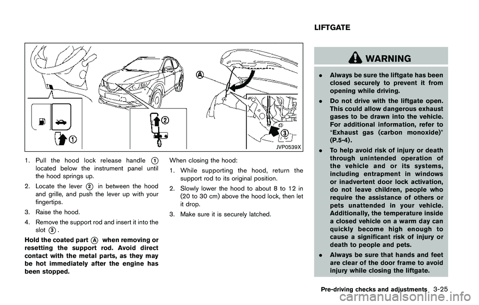
1. Pull the hood lock release handle*1
located below the instrument panel until
the hood springs up.
2. Locate the lever
*2in between the hood
and grille, and push the lever up with your
fingertips.
3. Raise the hood.
4. Remove the support rod and insert it into the
slot
*3.
Hold the coated part
*Awhen removing or
resetting the support rod. Avoid direct
contact with the metal parts, as they may
be hot immediately after the engine has
been stopped.When closing the hood:
1. While supporting the hood, return the
support rod to its original position.
2. Slowly lower the hood to about 8 to 12 in
(20 to 30 cm) above the hood lock, then let
it drop.
3. Make sure it is securely latched.
WARNING
.Always be sure the liftgate has been
closed securely to prevent it from
opening while driving.
.Do not drive with the liftgate open.
This could allow dangerous exhaust
gases to be drawn into the vehicle.
For additional information, refer to
“Exhaust gas (carbon monoxide)”
(P.5-4) .
.To help avoid risk of injury or death
through unintended operation of
the vehicle and or its systems,
including entrapment in windows
or inadvertent door lock activation,
do not leave children, people who
require the assistance of others or
pets unattended in your vehicle.
Additionally, the temperature inside
a closed vehicle on a warm day can
quickly become high enough to
cause a significant risk of injury or
death to people and pets.
.Always be sure that hands and feet
are clear of the door frame to avoid
injury while closing the liftgate.
Pre-driving checks and adjustments3-25
LIFTGATE
Page 174 of 508
WARNING
.Fuel is extremely flammable and
highly explosive under certain con-
ditions. You could be burned or
seriously injured if it is misused or
mishandled. Always stop the engine
and do not smoke or allow open
flames or sparks near the vehicle
when refueling.
.Fuel may be under pressure. Turn
the cap a half of a turn, and wait for
any“hissing”sound to stop to pre-
vent fuel from spraying out and
possibly causing personal injury.
Then remove the cap.
.Use only an original equipment type
fuel-filler cap as a replacement. It
has a built-in safety valve needed
for proper operation of the fuel
system and emission control sys-
tem. An incorrect cap can result in a
serious malfunction and possible
injury.
JVP0540X
OPENING THE FUEL-FILLER DOOR
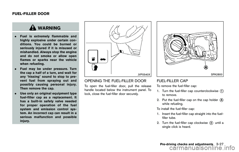
To open the fuel-filler door, pull the release
handle located below the instrument panel. To
lock, close the fuel-filler door securely.
SPA2800
FUEL-FILLER CAP
To remove the fuel-filler cap:
1. Turn the fuel-filler cap counterclockwise
*1
to remove.
2. Put the fuel-filler cap on the cap holder
*A
while refueling.
To install the fuel-filler cap:
1. Insert the fuel-filler cap straight into the fuel-
filler tube.
2. Turn the fuel-filler cap clockwise
*2until a
single click is heard.
Pre-driving checks and adjustments3-27
FUEL-FILLER DOOR
Page 175 of 508
3-28Pre-driving checks and adjustments
WARNING
.Gasoline is extremely flammable
and highly explosive under certain
conditions. You could be burned or
seriously injured if it is misused or
mishandled. Always stop engine
and do not smoke or allow open
flames or sparks near the vehicle
when refueling.
.Do not attempt to top off the fuel
tank after the fuel pump nozzle
shuts off automatically. Continued
refueling may cause fuel overflow,
resulting in fuel spray and possibly
a fire.
.Use only an original equipment type
fuel-filler cap as a replacement. It
has a built-in safety valve needed
for proper operation of the fuel
system and emission control sys-
tem. An incorrect cap can result in a
serious malfunction and possible
injury. It could also cause the mal-
function indicator light to come on.
.Never pour fuel into the throttle
body to attempt to start your vehi-
cle..Do not fill a portable fuel container
in the vehicle or trailer. Static elec-
tricity can cause an explosion of
flammable liquid, vapor or gas in
any vehicle or trailer. To reduce the
risk of serious injury or death when
filling portable fuel containers:
— Always place the container on
the ground when filling.
— Do not use electronic devices
when filling.
— Keep the pump nozzle in contact
with the container while you are
filling it.
— Use only approved portable fuel
containers for flammable liquid.
CAUTION
.If fuel is spilled on the vehicle body,
flush it away with water to avoid
paint damage.
.Insert the cap straight into the fuel-
filler tube, then tighten until the
fuel-filler cap clicks. Failure to tight-
en the fuel-filler cap properly maycause the
malfunction indicator
light (MIL) to illuminate. If the
light illuminates because the fuel-
filler cap is loose or missing, tighten
or install the cap and continue to
drive the vehicle. The
light
should turn off after a few driving
trips. If the
light does not turn
off after a few driving trips, have the
vehicle inspected. It is recom-
mended you visit a NISSAN dealer
for this service.
For additional information, see
“Malfunction Indicator Light (MIL)”
(P.2-16) .
.The LOOSE FUEL CAP warning
message will be displayed if the
fuel-filler cap is not properly tigh-
tened. It may take a few driving trips
for the message to be displayed.
Failure to tighten the fuel-filler cap
properly after the LOOSE FUEL CAP
warning message is displayed may
cause the
Malfunction Indicator
Light (MIL) to illuminate.
Page 290 of 508
THREE-WAY CATALYST
The three-way catalyst is an emission control
device installed in the exhaust system. Exhaust
gases in the three-way catalyst are burned at
high temperatures to help reduce pollutants.
WARNING
.The exhaust gas and the exhaust
system are very hot. Keep people,
animals and flammable materials
away from the exhaust system com-
ponents.
.Do not stop or park the vehicle over
flammable materials such as dry
grass, wastepaper or rags. They
may ignite and cause a fire.
CAUTION
.Do not use leaded gasoline. Depos-
its from leaded gasoline will ser-
iously reduce the three-way
catalyst’s ability to help reduce ex-
haust pollutants.
.Keep your engine tuned up. Mal-
functions in the ignition, fuel injec-tion, or electrical systems can cause
overrich fuel flow into the three-way
catalyst, causing it to overheat. Do
not keep driving if the engine mis-
fires, or if noticeable loss of perfor-
mance or other unusual operating
conditions are detected. Have the
vehicle inspected. It is recom-
mended you visit a NISSAN dealer
for this service.
.Avoid driving with an extremely low
fuel level. Running out of fuel could
cause the engine to misfire, dama-
ging the three-way catalyst.
.Do not race the engine while warm-
ing it up.
.Do not push or tow your vehicle to
start the engine.
TIRE PRESSURE MONITORING SYS-
TEM (TPMS)
Each tire, including the spare (if provided) ,
should be checked monthly when cold and
inflated to the inflation pressure recommended
by the vehicle manufacturer on the vehicle
placard or tire inflation pressure label. (If your
vehicle has tires of a different size than the size
indicated on the vehicle placard or tire inflation
pressure label, you should determine the propertire inflation pressure for those tires.)
As an added safety feature, your vehicle has
been equipped with a Tire Pressure Monitoring
System (TPMS) that illuminates a low tire
pressure telltale when one or more of your tires
is significantly under-inflated. Accordingly, when
the low tire pressure telltale illuminates, you
should stop and check your tires as soon as
possible, and inflate them to the proper pres-
sure. Driving on a significantly under-inflated tire
causes the tire to overheat and can lead to tire
failure. Under-inflation also reduces fuel effi-
ciency and tire tread life, and may affect the
vehicle’s handling and stopping ability.
Please note that the TPMS is not a substitute for
proper tire maintenance, and it is the driver’s
responsibility to maintain correct tire pressure,
even if under-inflation has not reached the level
to trigger illumination of the TPMS low tire
pressure telltale.
Your vehicle has also been equipped with a
TPMS malfunction indicator to indicate when the
system is not operating properly. The TPMS
malfunction indicator is combined with the low
tire pressure telltale. When the system detects a
malfunction, the telltale will flash for approxi-
mately one minute and then remain continuously
illuminated. This sequence will continue upon
subsequent vehicle start-ups as long as the
Starting and driving5-5
Page 302 of 508
chime sounds. The engine will start.
After step 3 is performed, when the ignition
switch is pushed without depressing the brake
pedal, the ignition switch position will change to
ACC.
NOTE:
.When the ignition switch is pushed to
the ON position or the engine is started
by the above procedures, the“Key
Battery Low”warning appears (on the
Vehicle information display) even if the
Intelligent Key is inside the vehicle.
This is not a malfunction. To turn off the
warning, touch the ignition switch with
the Intelligent Key again.
.If the“Key Battery Low”warning ap-
pears (on the Vehicle information dis-
play) , replace the battery as soon as
possible. (See“Intelligent Key battery
replacement”(P.8-23) .).Make sure the area around the vehicle is
clear.
.Check fluid levels such as engine oil, cool-
ant, brake fluid, and window washer fluid as
frequently as possible, or at least whenever
you refuel.
.Check that all windows and lights are clean.
.Visually inspect tires for their appearance
and condition. Also check tires for proper
inflation.
.Lock all doors.
.Position seat and adjust head restraints.
.Adjust inside and outside mirrors.
.Fasten seat belts and ask all passengers to
do likewise.
.Check the operation of warning lights when
the ignition switch is placed in the ON
position. (See “Warning lights, indicator
lights and audible reminders” (P.2-10) .)1. Apply the parking brake.
2.Continuously Variable Transmission
(CVT) model:
Move the shift lever to the P (Park) or N
(Neutral) position. (P is recommended.)
The starter is designed so that it does not
operate unless the shift lever is in either of
the above positions.
Manual Transmission (MT) model:
Move the shift lever to the N (Neutral)
position, and depress the clutch pedal to
the floor while starting the engine.
3. Crank the enginewith your foot off the
accelerator pedalby turning the ignition
switch to START. Release the switch when
the engine starts. If the engine starts, but
fails to run, repeat the above procedure.
.If the engine is very hard to start in
extremely cold weather or when restart-
ing, depress the accelerator pedal a little
(approximately 1/3 to the floor) and hold
it and then crank the engine. Release the
accelerator pedal when the engine starts.
.If the engine is very hard to start because
it is flooded, depress the accelerator
pedal all the way to the floor and hold it.
Crank the engine for 5 - 6 seconds. After
cranking the engine, release the accel-
Starting and driving5-17
BEFORE STARTING THE ENGINESTARTING THE ENGINE (model
without Intelligent Key system)
Page 308 of 508
High fluid temperature protection mode
This transmission has a high fluid temperature
protection mode. If the fluid temperature be-
comes too high (for example, when climbing
steep grades in high temperature with heavy
loads) , engine power and, under some condi-
tions, vehicle speed will be decreased auto-
matically to reduce the chance of transmission
damage. Vehicle speed can be controlled with
the accelerator pedal, but the engine and vehicle
speed may be limited.
Fail-safe
If the vehicle is driven under extreme
conditions, such as excessive wheel spin-
ning and subsequent hard braking, the
fail-safe system may be activated. The MIL
may illuminate to indicate the fail-safe
mode is activated. (See “Malfunction In-
dicator Light (MIL)” (P.2-16) .) This will
occur even if all electrical circuits are
functioning properly. In this case, place
the ignition switch in the OFF position and
wait for 10 seconds. Then turn the switch
back to the ON position. The vehicle
should return to its normal operating
condition. If it does not return to its normal
operating condition, have the transmission
checked and repaired, if necessary. It is
recommended you visit a NISSAN dealerfor this service.
WARNING
When the high fluid temperature pro-
tection mode or fail-safe operation
occurs, vehicle speed may be gradually
reduced. The reduced speed may be
lower than other traffic, which could
increase the chance of a collision. Be
especially careful when driving. If ne-
cessary, pull to the side of the road at a
safe place and allow the transmission
to return to normal operation, or have it
repaired if necessary.
Adaptive Shift Control (ASC)
The Adaptive Shift Control automatically oper-
ates when the transmission is in the “D” (Drive)
position and selects an appropriate gear de-
pending on the road conditions such as uphill or
downhill.
Control on uphill and curving roads:
A low gear is maintained that suits the degree of
the slope to allow smooth driving with a small
number of shifts.Control on downhill roads:
The Adaptive Shift Control shifts to a low gear
that suits the degree of the slope when the
accelerator pedal is depressed, and uses the
engine braking to help driving in the downhill.
Control on winding roads:
A low gear is maintained on continuous curves
that involve repeated acceleration and decelera-
tion, so that smooth acceleration is available
instantly when the accelerator pedal is de-
pressed.
NOTE:
.Adaptive Shift Control may not operate
when the transmission oil temperature
is low immediately after the start of
driving or when it is very hot.
.During some driving situations, hard
braking for example, the Adaptive Shift
Control may automatically operate. The
transmission may automatically shift to
a lower gear for engine braking. This
increases engine speed but not vehicle
speed. Vehicle speed is controlled by
the accelerator pedal when the vehicle
is in the Adaptive Shift Control mode.
.When the Adaptive Shift Control oper-
ates, the transmission sometimes
maintains a lower gear for a longer
period of time than when Adaptive
Starting and driving5-23
Page 309 of 508
5-24Starting and driving
Shift Control is not operating. Engine
speed will be higher for a specific
vehicle speed while Adaptive Shift
Control is operating than when Adap-
tive Shift Control is not operating.
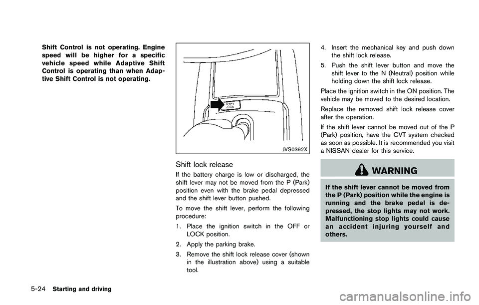
JVS0392X
Shift lock release
If the battery charge is low or discharged, the
shift lever may not be moved from the P (Park)
position even with the brake pedal depressed
and the shift lever button pushed.
To move the shift lever, perform the following
procedure:
1. Place the ignition switch in the OFF or
LOCK position.
2. Apply the parking brake.
3. Remove the shift lock release cover (shown
in the illustration above) using a suitable
tool.4. Insert the mechanical key and push down
the shift lock release.
5. Push the shift lever button and move the
shift lever to the N (Neutral) position while
holding down the shift lock release.
Place the ignition switch in the ON position. The
vehicle may be moved to the desired location.
Replace the removed shift lock release cover
after the operation.
If the shift lever cannot be moved out of the P
(Park) position, have the CVT system checked
as soon as possible. It is recommended you visit
a NISSAN dealer for this service.WARNING
If the shift lever cannot be moved from
the P (Park) position while the engine is
running and the brake pedal is de-
pressed, the stop lights may not work.
Malfunctioning stop lights could cause
an accident injuring yourself and
others.
Page 312 of 508
SPA2331
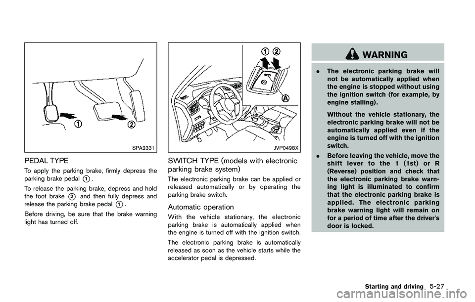
PEDAL TYPE
To apply the parking brake, firmly depress the
parking brake pedal
*1.
To release the parking brake, depress and hold
the foot brake
*2and then fully depress and
release the parking brake pedal
*1.
Before driving, be sure that the brake warning
light has turned off.
JVP0498X
SWITCH TYPE (models with electronic
parking brake system)
The electronic parking brake can be applied or
released automatically or by operating the
parking brake switch.
Automatic operation
With the vehicle stationary, the electronic
parking brake is automatically applied when
the engine is turned off with the ignition switch.
The electronic parking brake is automatically
released as soon as the vehicle starts while the
accelerator pedal is depressed.
WARNING
.The electronic parking brake will
not be automatically applied when
the engine is stopped without using
the ignition switch (for example, by
engine stalling) .
Without the vehicle stationary, the
electronic parking brake will not be
automatically applied even if the
engine is turned off with the ignition
switch.
.Before leaving the vehicle, move the
shift lever to the 1 (1st) or R
(Reverse) position and check that
the electronic parking brake warn-
ing light is illuminated to confirm
that the electronic parking brake is
applied. The electronic parking
brake warning light will remain on
for a period of time after the driver’s
door is locked.
Starting and driving5-27
Page 313 of 508
5-28Starting and driving
CAUTION
When parking in an area where the
outside temperature is below 328F
(08C) , do not apply the parking brake
to prevent it from freezing.
For safe parking, place the shift lever in
the 1 (1st) or R (Reverse) position and
securely block the wheels.
NOTE:
.To keep the electronic parking brake
released after the engine is turned off,
place the ignition switch in the OFF
position, depress the brake pedal and
push down the parking brake switch
before opening the driver’s door.
.If a malfunction occurs in the electric
parking brake system (for example, due
to battery discharge) , it is recom-
mended to contact a NISSAN dealer.
Manual operation
The electronic parking brake will not be auto-
matically applied if the engine is stopped without
using the ignition switch (for example, by engine
stalling) . In such a case, you have to apply the
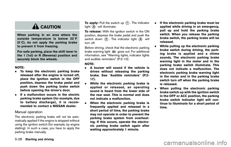
parking brake manually.To apply:Pull the switch up
*1. The indicator
light
*Awill illuminate.
To release:With the ignition switch in the ON
position, depress the brake pedal and push the
switch down
*2. The indicator light*Awill
turn off.
Before driving, check that the electronic parking
brake warning light
goes out. For additional
information, see “Warning lights, indicator lights
and audible reminders” (P.2-10) .
NOTE:
.A buzzer will sound if the vehicle is
driven without releasing the parking
brake. See“Audible reminders”(P.2-
17) .
.While the electronic parking brake is
applied or released, an operating
sound is heard from the lower side of
the rear seat. This is normal and does
not indicate a malfunction.
.When the electronic parking brake is
frequently applied and released in a
short period of time, the parking brake
may not operate in order to prevent the
parking brake system from overheat-
ing. If this occurs, operate the electro-
nic parking brake switch again after
waiting approximately 1 minute..If the electronic parking brake must be
applied while driving in an emergency,
pull up and hold the parking brake
switch. When you release the parking
brake switch, the parking brake will be
released.
.While pulling up the electronic parking
brake switch during driving, the park-
ing brake is applied and a chime
sounds. The electronic parking brake
warning light in the meter and in the
parking brake switch illuminate. This
does not indicate a malfunction. The
electronic parking brake warning light
in the meter and in the parking brake
switch turn off when the parking brake
is released.
.When pulling the electronic parking
brake switch up with the ignition switch
in the OFF or ACC position, the parking
brake switch indicator light will con-
tinue to illuminate for a short period of
time.