engine coolant NISSAN ROGUE SPORT 2018 Owners Manual
[x] Cancel search | Manufacturer: NISSAN, Model Year: 2018, Model line: ROGUE SPORT, Model: NISSAN ROGUE SPORT 2018Pages: 512, PDF Size: 3.33 MB
Page 17 of 512

0-8Illustrated table of contents
JVC0581X
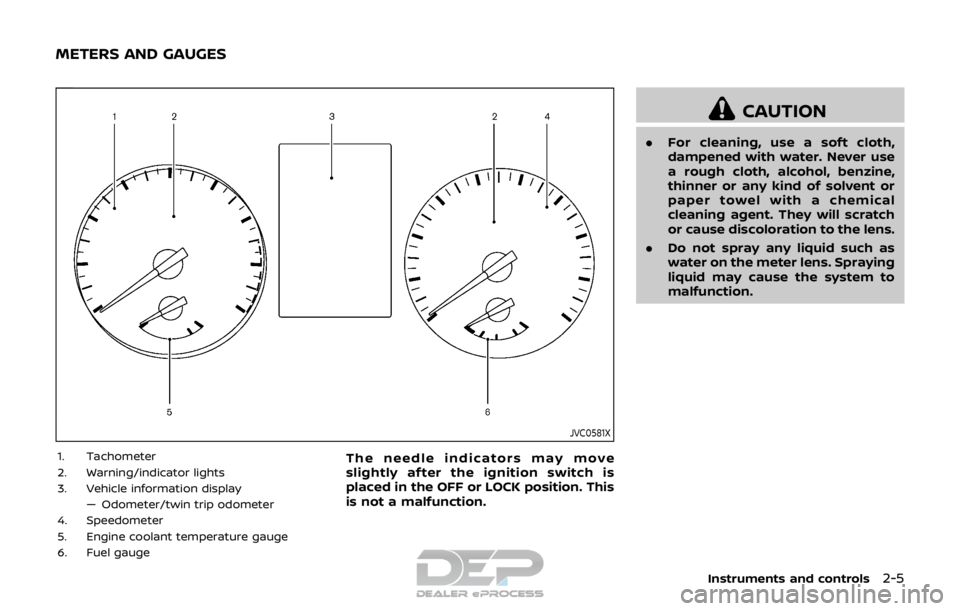
1. Tachometer (P.2-7)
2. Warning/indicator lights (P.2-10)
3. Vehicle information display (P.2-18)— Odometer/twin trip odometer (P.2-6)
4. Speedometer (P.2-6)
5. Engine coolant temperature gauge (P.2-7)
6. Fuel gauge (P.2-8)
METERS AND GAUGES
Page 18 of 512

JVC1070X
MR20DD ENGINE MODEL
1. Engine coolant reservoir (P.8-5)
2. Engine oil filler cap (P.8-6)
3. Brake and clutch* fluid reservoir (P.8-9)
4. Air cleaner (P.8-15)
5. Window washer fluid reservoir (P.8-10)
6. Drive belt (P.8-13)7. Engine oil dipstick (P.8-6)
8. Battery (P.8-11)
9. Fuse/fusible link box (P.8-18)
*: For Manual Transmission (MT) Model
Illustrated table of contents0-9
ENGINE COMPARTMENT
Page 78 of 512

2 Instruments and controls
Cockpit ........................................................................\
.......................... 2-3
Instrument panel ........................................................................\
.. 2-4
Meters and gauges ..................................................................... 2-5Speedometer and odometer ........................................ 2-6
Tachometer ........................................................................\
........ 2-7
Engine coolant temperature gauge ....................... 2-7
Fuel gauge ........................................................................\
........... 2-8
Instrument brightness control .................................... 2-9
Continuously Variable Transmission (CVT)
position indicator (if so equipped) ........................... 2-9
Warning lights, indicator lights and
audible reminders ..................................................................... 2-10 Checking lights ..................................................................... 2-10
Warning lights ........................................................................\
2-10
Indicator lights ...................................................................... 2-16
Audible reminders .............................................................. 2-17
Vehicle information display ............................................... 2-18 How to use the vehicle
information display ........................................................... 2-19
Startup display ...................................................................... 2-19
Settings ........................................................................\
............... 2-19
Vehicle information display warnings
and indicators ........................................................................\
2-28
Trip computer ........................................................................\
2-34
Clock and outside air temperature ...................... 2-36 Security systems ....................................................................... 2-36
Vehicle Security System .............................................. 2-36
NISSAN Vehicle Immobilizer System ................. 2-38
Wiper and washer switch ................................................... 2-39 Windshield wiper and washer operation ...... 2-40
Rear window wiper and washer switch ................. 2-41
Rear window and outside mirror
defroster switch ........................................................................\
. 2-42
Headlight and turn signal switch ................................ 2-43 Headlight switch ............................................................... 2-43
Turn signal switch ........................................................... 2-48
Fog light switch (if so equipped) ......................... 2-48
Horn ........................................................................\
............................. 2-49
Heated steering wheel (if so equipped) .................. 2-49
Heated seats (if so equipped) ......................................... 2-50
Intelligent Lane Intervention (I-LI) switch (if
so equipped) ........................................................................\
......... 2-51
Blind Spot Warning (BSW) switch (if
so equipped) ........................................................................\
......... 2-51
Vehicle Dynamic Control (VDC) off switch ........... 2-52
Intelligent 4x4 LOCK switch (if so equipped) ...... 2-52
ECO mode switch ..................................................................... 2-52
Power outlet ........................................................................\
......... 2-53
Storage ........................................................................\
...................... 2-54 Cup holders ........................................................................\
... 2-54
Page 82 of 512

JVC0581X
1. Tachometer
2. Warning/indicator lights
3. Vehicle information display— Odometer/twin trip odometer
4. Speedometer
5. Engine coolant temperature gauge
6. Fuel gaugeThe needle indicators may move
slightly after the ignition switch is
placed in the OFF or LOCK position. This
is not a malfunction.
CAUTION
. For cleaning, use a soft cloth,
dampened with water. Never use
a rough cloth, alcohol, benzine,
thinner or any kind of solvent or
paper towel with a chemical
cleaning agent. They will scratch
or cause discoloration to the lens.
. Do not spray any liquid such as
water on the meter lens. Spraying
liquid may cause the system to
malfunction.
Instruments and controls2-5
METERS AND GAUGES
Page 84 of 512

Resetting twin trip odometer:
Push the TRIP RESET switch
for more
than 1 second to reset the trip odometer
to zero.
JVI0951X
TACHOMETER
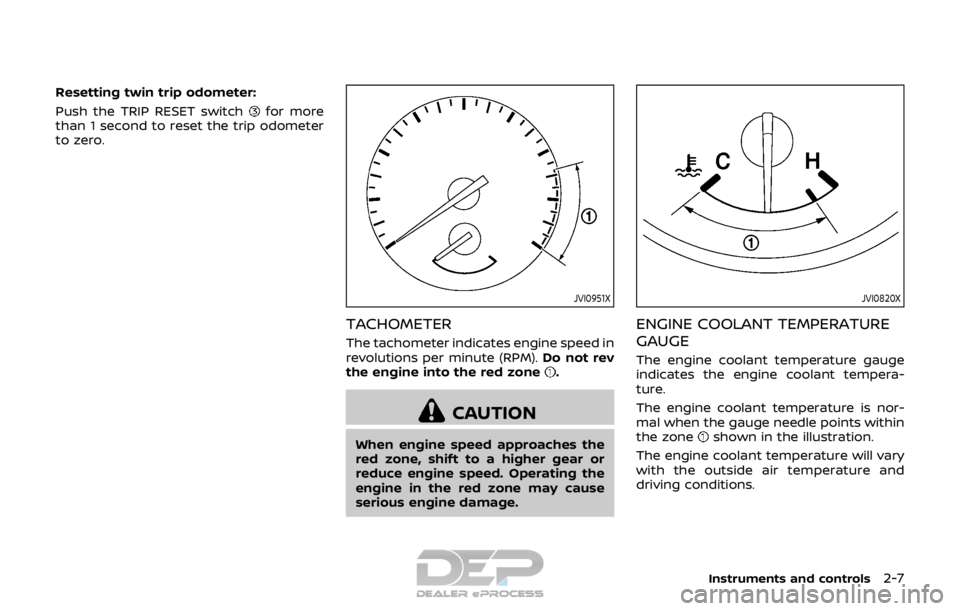
The tachometer indicates engine speed in
revolutions per minute (RPM). Do not rev
the engine into the red zone
.
CAUTION
When engine speed approaches the
red zone, shift to a higher gear or
reduce engine speed. Operating the
engine in the red zone may cause
serious engine damage.
JVI0820X
ENGINE COOLANT TEMPERATURE
GAUGE
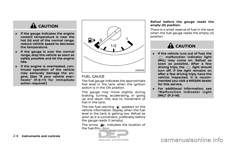
The engine coolant temperature gauge
indicates the engine coolant tempera-
ture.
The engine coolant temperature is nor-
mal when the gauge needle points within
the zone
shown in the illustration.
The engine coolant temperature will vary
with the outside air temperature and
driving conditions.
Instruments and controls2-7
Page 85 of 512

2-8Instruments and controls
CAUTION
.If the gauge indicates the engine
coolant temperature is near the
hot (H) end of the normal range,
reduce vehicle speed to decrease
the temperature.
. If the gauge is over the normal
range, stop the vehicle as soon as
safely possible and let the engine
idle.
. If the engine is overheated, con-
tinued operation of the vehicle
may seriously damage the en-
gine. (See “If your vehicle over-
heats” (P.6-11) for immediate
action required.)
JVI0640X
FUEL GAUGE
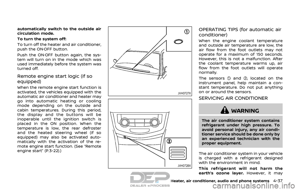
The fuel gauge indicates the approximate
fuel level in the tank when the ignition
switch is in the ON position.
The gauge may move slightly during
braking, turning, accelerating, or going
up and down hills due to movement of
fuel in the tank.
The low fuel warning
appears on the
vehicle information display when the fuel
level in the tank is getting low. Refuel as
soon as it is convenient, preferably before
the gauge reads 0 (empty).
The arrow,
, indicates the location of
the fuel-filler door. Refuel before the gauge reads the
empty (0) position.
There is a small reserve of fuel in the tank
when the fuel gauge reads the empty (0)
position.
CAUTION
.
If the vehicle runs out of fuel, themalfunction indicator light
(MIL) may come on. Refuel as
soon as possible. After a few
driving trips, the
light should
turn off. If the light remains on
after a few driving trips, have the
vehicle inspected. It is recom-
mended you visit a NISSAN dealer
for this service.
. For additional information, see
“Malfunction Indicator Light
(MIL)” (P.2-16).
Page 213 of 512

4-34Heater, air conditioner, audio and phone systems
selected, the air conditioner automatically
turns on if the outside temperature is
more than 36°F (2°C). This dehumidifies
the air which helps defog the windshield.
The air recirculation mode automatically
turns off, allowing outside air to be drawn
into the passenger compartment to
further improve the defogging perfor-
mance.
The air conditioner is always on in front
defroster or
mode, regardless of
whether the indicator light is on or off.
NOTE:
. The air conditioner system should
be operated for approximately 10
minutes at least once a month. This
helps prevent damage to the air
conditioner system due to the lack
of lubrication.
. A visible mist may be seen coming
from the ventilators in hot, humid
conditions as the air is cooled ra-
pidly. This does not indicate a mal-
function.
. If the engine coolant temperature
becomes too high, the air recircula-
tion mode will be activated and the
indicator light will come on automa-
tically.
. If the engine coolant temperature
gauge indicates engine coolant tem-
perature over the normal range, turn the air conditioner off. (See “If your
vehicle overheats” (P.6-11).)
Page 216 of 512

automatically switch to the outside air
circulation mode.
To turn the system off:
To turn off the heater and air conditioner,
push the ON·OFF button.
Push the ON·OFF button again, the sys-
tem will turn on in the mode which was
used immediately before the system was
turned off.
Remote engine start logic (if so
equipped)
When the remote engine start function is
activated, the vehicles equipped with the
automatic air conditioner and heater may
go into automatic heating or cooling
mode depending on the outside and
cabin temperatures. During this period,
the display and the buttons will be
inoperable until the ignition switch is
placed in the ON position. When the
temperature is low, the rear defroster
and the heated steering wheel (if so
equipped) may also be activated auto-
matically with the activation of the re-
mote engine start function. (See “Remote
engine start” (P.3-22).)
JVH0727X
JVH0728X
OPERATING TIPS (for automatic air
conditioner)
When the engine coolant temperature
and outside air temperature are low, the
air flow from the foot outlets may not
operate for a maximum of 150 seconds.
However, this is not a malfunction. After
the coolant temperature warms up, air
flow from the foot outlets will operate
normally.
The sensors
and, located on the
instrument panel, help maintain a con-
stant temperature. Do not put anything
on or around the sensors.
SERVICING AIR CONDITIONER
WARNING
The air conditioner system contains
refrigerant under high pressure. To
avoid personal injury, any air condi-
tioner service should be done only by
an experienced technician with the
proper equipment.
The air conditioner system in your vehicle
is charged with a refrigerant designed
with the environment in mind.
This refrigerant will not harm the
earth’s ozone layer. However, it may
Heater, air conditioner, audio and phone systems4-37
Page 288 of 512

Increasing fuel economy ................................................. 5-100
Intelligent 4x4 (if so equipped) ................................... 5-100Intelligent 4x4 LOCK switch operations ...... 5-102
Parking/parking on hills ................................................... 5-104
Electric power steering ..................................................... 5-105
Brake system ........................................................................\
.... 5-106 Braking precautions ..................................................... 5-106
Brake assist ........................................................................\
........ 5-107
Brake assist ........................................................................\
. 5-107
Anti-lock Braking System (ABS) ........................... 5-107
Vehicle Dynamic Control (VDC) system ............... 5-108
Chassis control ........................................................................\
5-110 Intelligent Trace Control ........................................... 5-110 Intelligent Engine Brake (Continuously
Variable Transmission (CVT) models) .......... 5-111
Active Ride Control ..................................................... 5-112
Hill Start Assist system ..................................................... 5-113
Cold weather driving ......................................................... 5-113 Freeing a frozen door lock ................................... 5-113
Anti-freeze ........................................................................\
.. 5-113
Battery ........................................................................\
........... 5-113
Draining of coolant water ..................................... 5-113
Tire equipment ............................................................... 5-114
Special winter equipment ..................................... 5-114
Driving on snow or ice ............................................. 5-114
Page 302 of 512

JVS0404X
INTELLIGENT KEY BATTERY DIS-
CHARGE
If the battery of the Intelligent Key is
discharged, or environmental conditions
interfere with the Intelligent Key opera-
tion, start the engine according to the
following procedure:
1. Move the shift lever to the P (Park)position (for CVT models) or the shift
lever to the N (Neutral) position (for MT
models).
2. Firmly apply the foot brake.
3. Touch the ignition switch with the Intelligent Key as illustrated. (A chime
will sound.) 4. Push the ignition switch while depres-
sing the brake pedal within 10 sec-
onds after the chime sounds. The
engine will start.
After step 3 is performed, when the
ignition switch is pushed without depres-
sing the brake pedal, the ignition switch
position will change to ACC.
NOTE:
. When the ignition switch is pushed
to the ON position or the engine is
started by the above procedures, the
“Key Battery Low” warning appears
(on the Vehicle information display)
even if the Intelligent Key is inside
the vehicle. This is not a malfunction.
To turn off the warning, touch the
ignition switch with the Intelligent
Key again.
. If the “Key Battery Low” warning
appears (on the Vehicle information
display), replace the battery as soon
as possible. (See “Intelligent Key
battery replacement” (P.8-23).) .
Make sure the area around the vehicle
is clear.
. Check fluid levels such as engine oil,
coolant, brake fluid, and window
washer fluid as frequently as possible,
or at least whenever you refuel.
. Check that all windows and lights are
clean.
. Visually inspect tires for their appear-
ance and condition. Also check tires
for proper inflation.
. Lock all doors.
. Position seat and adjust head re-
straints.
. Adjust inside and outside mirrors.
. Fasten seat belts and ask all passen-
gers to do likewise.
. Check the operation of warning lights
when the ignition switch is placed in
the ON position. (See “Warning lights,
indicator lights and audible remin-
ders” (P.2-10).)
Starting and driving5-17
BEFORE STARTING THE ENGINE