NISSAN SENTRA 2021 Owners Manual
Manufacturer: NISSAN, Model Year: 2021, Model line: SENTRA, Model: NISSAN SENTRA 2021Pages: 528, PDF Size: 3.51 MB
Page 401 of 528
•Tire type and condition may also af-
fect braking effectiveness.
– When replacing tires, install the
specified size of tires on all four
wheels.
– When installing a spare tire, make
sure that it is the proper size and
type as specified on the Tire and
Loading Information label. For ad-
ditional information, refer to “Tire
and Loading Information label” in
the “Technical and consumer in-
formation” section of this manual.
– For additional information, refer
to “Wheels and tires” in the “Do-it-
yourself ” section of this manual.
The ABS controls the brakes so the wheels
do not lock during hard braking or when
braking on slippery surfaces. The system
detects the rotation speed at each wheel
and varies the brake fluid pressure to pre-
vent each wheel from locking and sliding.
By preventing each wheel from locking, the
system helps the driver maintain steering
control and helps to minimize swerving
and spinning on slippery surfaces.Using the system
Depress the brake pedal and hold it down.
Depress the brake pedal with firm steady
pressure, but do not pump the brakes. The
Anti-lock Braking System will operate to
prevent the wheels from locking up. Steer
the vehicle to avoid obstacles.
Page 402 of 528
BRAKE ASSIST
When the force applied to the brake pedal
exceeds a certain level, the Brake Assist is
activated generating greater braking force
than a conventional brake booster even
with light pedal force.indicator light in the instrument panel
flashes to note the following:
• The road may be slippery or the systemmay determine some action is required
to help keep the vehicle on the steered
path.
• You may feel a pulsation in the brake pedal and hear a noise or vibration from
under the hood. This is normal and indi-
cates that the VDC system is working
properly.
• Adjust your speed and driving to the road conditions.
For additional information, refer to “Slip in-
dicator light” and ”Vehicle Dynamic Control
(VDC) OFF indicator light” in the ”Instru-
ments and controls” section of this manual.
If a malfunction occurs in the system, the
indicator light comes on in the instru-
ment panel. The VDC system automatically
turns off when the indicator light is off.
The vehicle information display is used to
turn off the VDC system. The
indicator
light and the AEB system warning light illu-
minates to indicate the VDC system is off.
VEHICLE DYNAMIC CONTROL (VDC)
SYSTEM
5-116Starting and driving
Page 403 of 528
When the vehicle information display is
used to turn off the VDC system, the sys-
tem still operates to prevent one drive
wheel from slipping by transferring power
to a non-slipping drive wheel. The
indicator light flashes if this occurs. All
other VDC functions are off and the
indicator light will not flash.
The VDC system is automatically reset to
on when the ignition switch is placed in the
OFF position then back to the ON position.
The computer has a built-in diagnostic fea-
ture that tests the system each time you
start the engine and move the vehicle for-
ward or in reverse at a slow speed. When
the self-test occurs, you may hear a clunk
noise and/or feel a pulsation in the brake
pedal. This is normal and is not an indica-
tion of a malfunction.
indicator light may flash
or theindicator light may
illuminate.
• If brake related parts such as brake
pads, rotors and calipers are not
NISSAN recommended or are ex-
tremely deteriorated, the VDC sys-
tem may not operate properly and
the
indicator light may
illuminate. •
If engine control related parts are not
NISSAN recommended or are ex-
tremely deteriorated, the
indica-
tor light may illuminate.
• When driving on extremely inclined
surfaces such as higher banked cor-
ners, the VDC system may not oper-
ate properly and the
indicator
light may flash or theindicator
light may illuminate. Do not drive on
these types of roads.
• When driving on an unstable surface
such as a turntable, ferry, elevator or
ramp, the
indicator light may
flash or theindicator light may
illuminate. This is not a malfunction.
Restart the engine af ter driving onto
a stable surface.
• If wheels or tires other than the
NISSAN recommended ones are
used, the VDC system may not oper-
ate properly and the
indicator
light may flash or theindicator
light may illuminate.
• The VDC system is not a substitute
for winter tires or tire chains on a
snow covered road.
Starting and driving5-117
Page 404 of 528
RISE-UP AND BUILD-UP
The system gradually adjusts braking
power during normal braking to help pro-
vide an enhanced brake feel.
BRAKE FORCE DISTRIBUTION
During braking while driving through turns,
the system optimizes the distribution of
force to each of the front and rear wheels
depending on the radius of the turn.
indicator light may flash
or theindicator light may
illuminate.
• If brake related parts such as brake
pads, rotors and calipers are not
NISSAN recommended or are ex-
tremely deteriorated, the VDC sys-
tem may not operate properly and
the
indicator light may
illuminate.
• If engine control related parts are not
NISSAN recommended or are ex-
tremely deteriorated, the
indica-
tor light may illuminate.
• When driving on extremely inclined
surfaces such as higher banked cor-
ners, the VDC system may not oper-
ate properly and the
indicator
light may flash or theindicator
light may illuminate. Do not drive on
these types of roads. •
When driving on an unstable surface
such as a turntable, ferry, elevator or
ramp, the
indicator light may
flash or theindicator light may
illuminate. This is not a malfunction.
Restart the engine af ter driving onto
a stable surface.
• If wheels or tires other than the
NISSAN recommended ones are
used, the VDC system may not oper-
ate properly and the
indicator
light may flash or theindicator
light may illuminate.
• The VDC system is not a substitute
for winter tires or tire chains on a
snow covered road.
5-118Starting and driving
Page 405 of 528
The chassis control is an electric control
module that includes the following func-
tions:
• Intelligent Trace Control
• Active Ride Control
INTELLIGENT TRACE CONTROL
(I-TC)
This system senses driving based on the
driver’s steering and acceleration/braking
patterns, and controls brake pressure at
individual wheels to aid tracing at corners
and help smooth vehicle response.
The I-TC can be set to on (enabled) or off
(disabled) through the vehicle information
display “Settings” page. For additional infor-
mation, refer to “Vehicle information dis-
play” in the “Instruments and controls” sec-
tion of this manual.
When the VDC system is turned off, the I-TC
is also turned off.
Page 406 of 528
When the vehicle is stopped on a hill, the hill
start assist system automatically keeps
the brakes applied to help prevent the ve-
hicle from rolling backward in the time it
takes the driver to release the brake pedal
and apply the accelerator.
The hill start assist system will operate au-
tomatically under the following conditions:
• The transmission is shif ted to a forwardor reverse gear.
• The vehicle is stopped completely on a hill by applying the brake. The maximum
holding time is 2 seconds. Af ter 2 sec-
onds the vehicle will begin to roll back and
the hill start assist system will stop oper-
ating completely.
The hill start assist system will not operate
when the shif t lever is placed in the N (Neu-
tral) or P (Park) position or on a flat and level
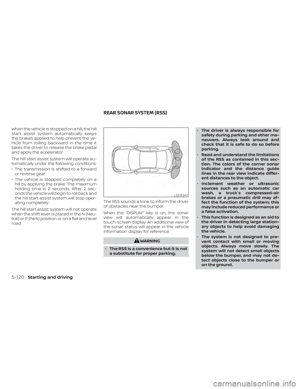
road. The RSS sounds a tone to inform the driver
of obstacles near the bumper.
When the “DISPLAY” key is on, the sonar
view will automatically appear in the
touch-screen display. An additional view of
the sonar status will appear in the vehicle
information display for reference.
Page 407 of 528
•The system may not detect the fol-
lowing objects: fluff y objects such as
snow, cloth, cotton, glass, wool, etc.;
thin objects such as rope, wire and
chain, etc.; or wedge-shaped objects.
If your vehicle sustains damage to the
bumper fascia, leaving it misaligned or
bent, the sensing zone may be altered
causing inaccurate measurement of ob-
stacles or false alarms.
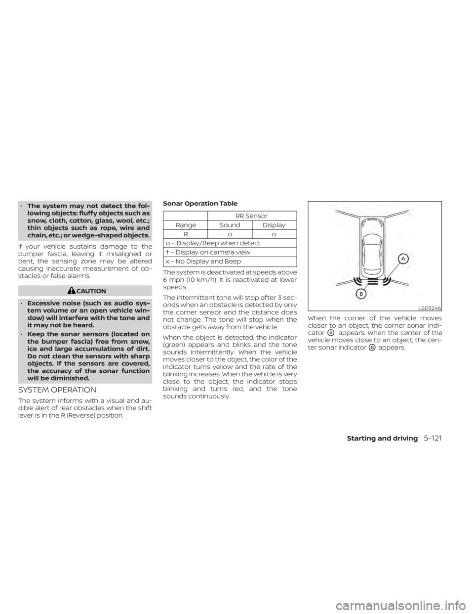
LSD3246
Page 408 of 528
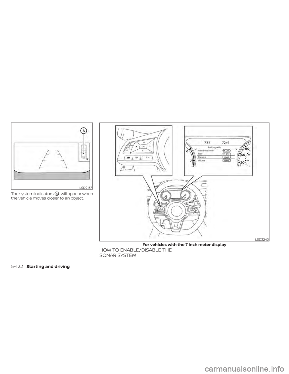
The system indicatorsOAwill appear when
the vehicle moves closer to an object.
HOW TO ENABLE/DISABLE THE
SONAR SYSTEM
LSD2137
LSD3240
For vehicles with the 7 inch meter display
Page 409 of 528
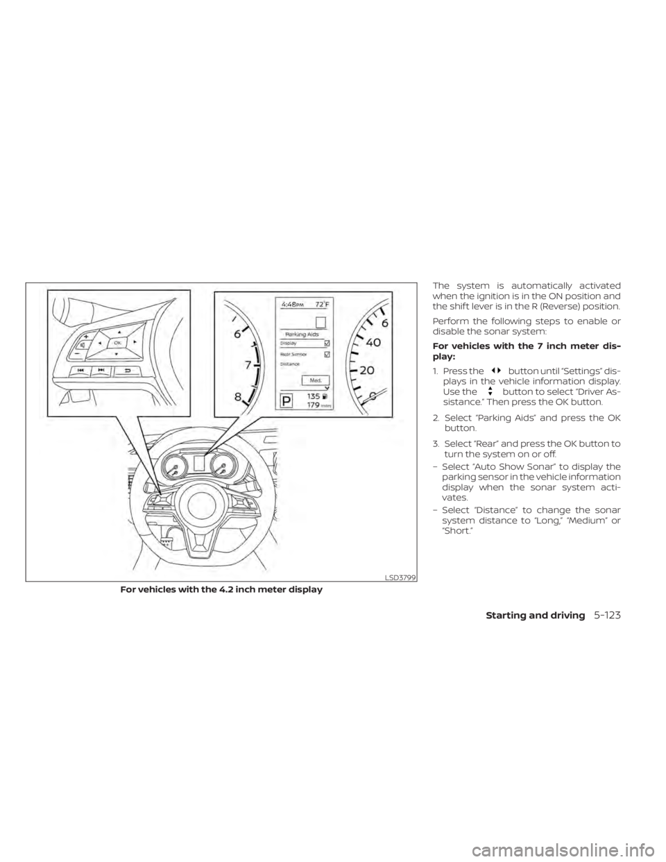
The system is automatically activated
when the ignition is in the ON position and
the shif t lever is in the R (Reverse) position.
Perform the following steps to enable or
disable the sonar system:
For vehicles with the 7 inch meter dis-
play:
1. Press the
button until “Settings” dis-
plays in the vehicle information display.
Use the
button to select “Driver As-
sistance.” Then press the OK button.
2. Select “Parking Aids” and press the OK button.
3. Select “Rear” and press the OK button to turn the system on or off.
– Select “Auto Show Sonar” to display the parking sensor in the vehicle information
display when the sonar system acti-
vates.
– Select “Distance” to change the sonar system distance to “Long,” “Medium” or
“Short.”
LSD3799
For vehicles with the 4.2 inch meter display
Starting and driving5-123
Page 410 of 528
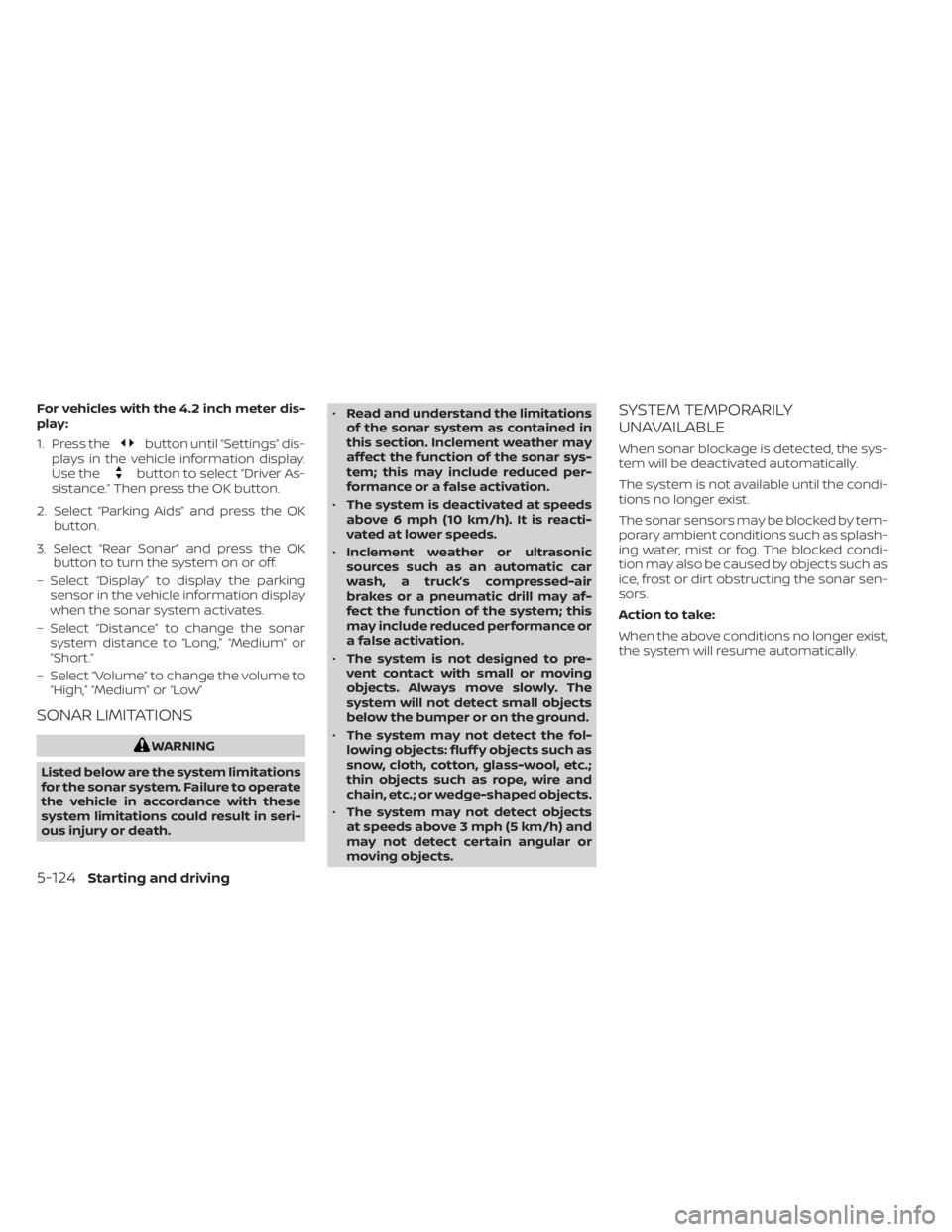
For vehicles with the 4.2 inch meter dis-
play:
1. Press the
button until “Settings” dis-
plays in the vehicle information display.
Use the
button to select “Driver As-
sistance.” Then press the OK button.
2. Select “Parking Aids” and press the OK button.
3. Select “Rear Sonar” and press the OK button to turn the system on or off.
– Select “Display” to display the parking sensor in the vehicle information display
when the sonar system activates.
– Select “Distance” to change the sonar system distance to “Long,” “Medium” or
“Short.”
– Select “Volume” to change the volume to “High,” “Medium” or “Low”
SONAR LIMITATIONS