NISSAN TEANA 2003 Service Manual
Manufacturer: NISSAN, Model Year: 2003, Model line: TEANA, Model: NISSAN TEANA 2003Pages: 3502, PDF Size: 74.56 MB
Page 2591 of 3502
SQUEAK AND RATTLE TROUBLE DIAGNOSES
IP-9
C
D
E
F
G
H
J
K
L
MA
B
IP
SBT844
Page 2592 of 3502
IP-10
INSTRUMENT PANEL ASSEMBLY
INSTRUMENT PANEL ASSEMBLYPFP:68200
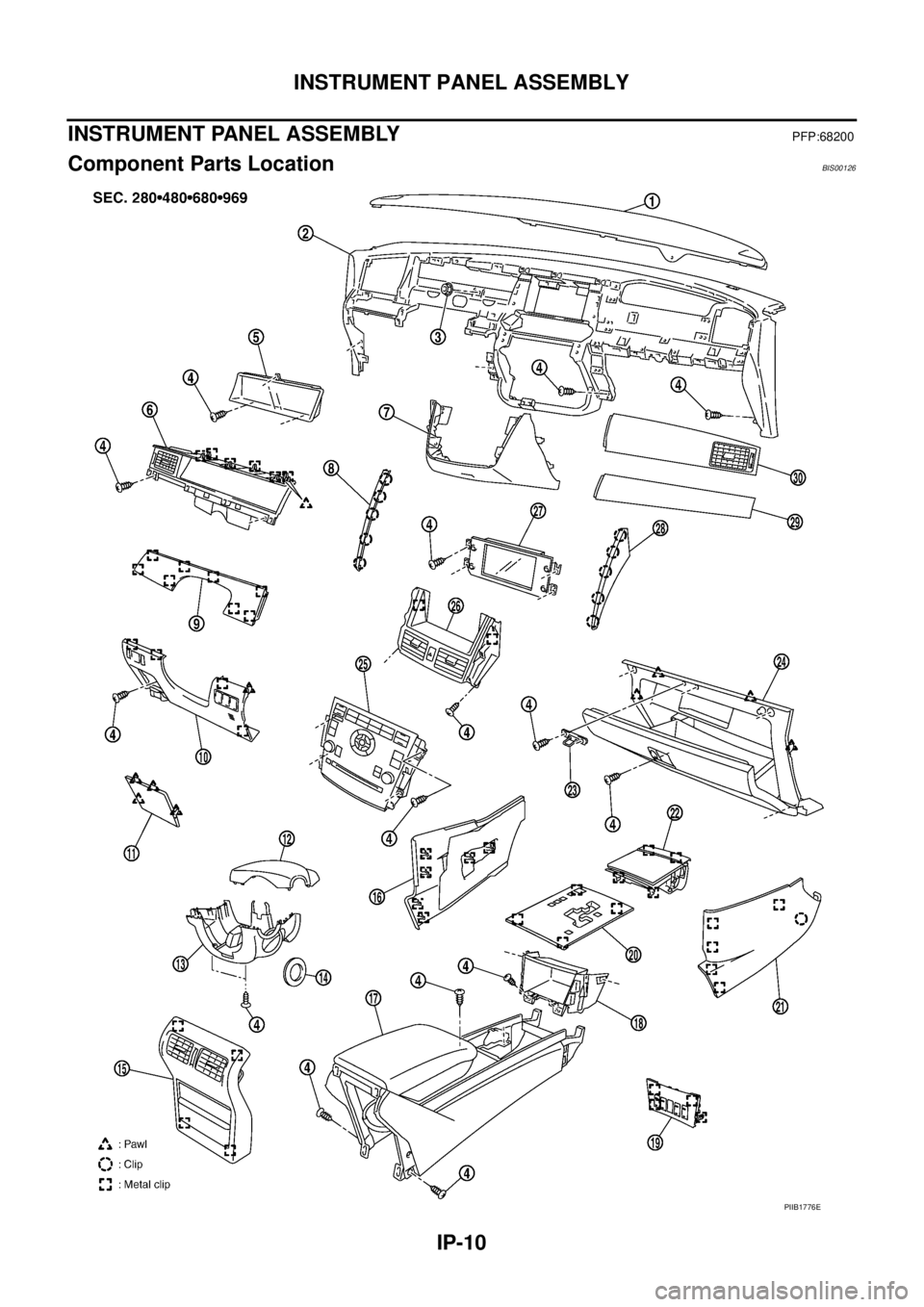
Component Parts LocationBIS00126
PIIB1776E
Page 2593 of 3502
![NISSAN TEANA 2003 Service Manual INSTRUMENT PANEL ASSEMBLY
IP-11
C
D
E
F
G
H
J
K
L
MA
B
IP
Removal and InstallationBIS00127
WORK ITEM TABLE
[ ]: The number shows the removal order.
NOTE:
*1: Assemble console box and cup holder. Ref NISSAN TEANA 2003 Service Manual INSTRUMENT PANEL ASSEMBLY
IP-11
C
D
E
F
G
H
J
K
L
MA
B
IP
Removal and InstallationBIS00127
WORK ITEM TABLE
[ ]: The number shows the removal order.
NOTE:
*1: Assemble console box and cup holder. Ref](/img/5/57392/w960_57392-2592.png)
INSTRUMENT PANEL ASSEMBLY
IP-11
C
D
E
F
G
H
J
K
L
MA
B
IP
Removal and InstallationBIS00127
WORK ITEM TABLE
[ ]: The number shows the removal order.
NOTE:
*1: Assemble console box and cup holder. Refer to IP-19, "
CENTER CONSOLE" .
*2: Assemble damper and glove box illumination. Refer to IP-20, "
INSTRUMENT PASSENGER LOWER
PA N E L" .
1. Instrument panel pad 2. Instrument panel 3. Nut
4. Screw 5. Combination meter 6. Cluster lid A
7. Instrument center lower panel 8. Instrument panel finisher 9. Instrument panel pad A
10. instrument driver lower cover 11. Fuse block lid 12. Steering column upper cover
13. Steering column lower cover 14. Steering lock escutcheon 15. console rear cover
16. instrument panel lower cover (Lh) 17. Center console 18. Instrument panel stay cover
19. Console switch finisher 20. A/T console finisher 21. Instrument pane lower cover (RH)
22. Front ashtray 23. Glove box striker 24. Instrument passenger lower panel
25. Cluster lid C 26. Cluster lid D 27. Display unit
28. Instrument panel finisher D 29. Instrument panel pad B 30. Instrument passenger lower panel
Component Parts LocationReference
pageInstrument
panel & padCombination
meterDisplay unitCenter
console
A Kicking plate (LH/RH)EI-39
[ 1 ]
B Front pillar garnish (LH/RH)EI-39
[ 2 ]
C A/T selector lever knobAT- 2 1 3
[ 3 ] [ 1 ]
D A/T console finisherIP-12
[ 4 ] [ 2 ]
E Console switch finisherIP-12
[ 5 ] [ 3 ]
F Front ashtrayIP-12
[ 6 ] [ 4 ]
G Instrument panel lower cover (LH/RH)IP-13
[ 7 ] [ 5 ]
H Instrument panel stay coverIP-13
[ 8 ] [ 6 ]
I Console rear coverIP-13
[ 9 ] [ 7 ]
J Center console (*1)IP-14
[ 10 ] [ 8 ]
K Instrument passenger lower panel (*2)IP-14
[ 11 ]
L Instrument panel finisher (C/D)IP-14
[ 12 ] [ 1 ] C only [ 1 ]
M Cluster lid CIP-15
[ 13 ] [ 2 ]
N Cluster lid DIP-15
[ 14 ] [ 3 ]
O Display unitAV- 6 0
[ 15 ] [ 4 ]
P Fuse block lidIP-16
[ 16 ]
Q Instrument driver lower panelIP-16
[ 17 ]
R Steering lock escutcheonIP-16
[ 18 ] [ 2 ]
S Steering column upper/lower coverIP-16
[ 19 ] [ 3 ]
T Instrument panel pad AIP-16
[ 20 ] [ 4 ]
U Cluster lid AIP-17
[ 21 ] [ 5 ]
V Combination meterIP-17
[ 22 ] [ 6 ]
W Instrument panel pad BIP-17
[ 23 ]
X Instrument passenger upper panelIP-17
[ 24 ]
Y Instrument panel & padIP-17
[ 25 ]
Z Center instrument lower panelIP-18
[ 26 ]
Page 2594 of 3502
IP-12
INSTRUMENT PANEL ASSEMBLY
REMOVAL
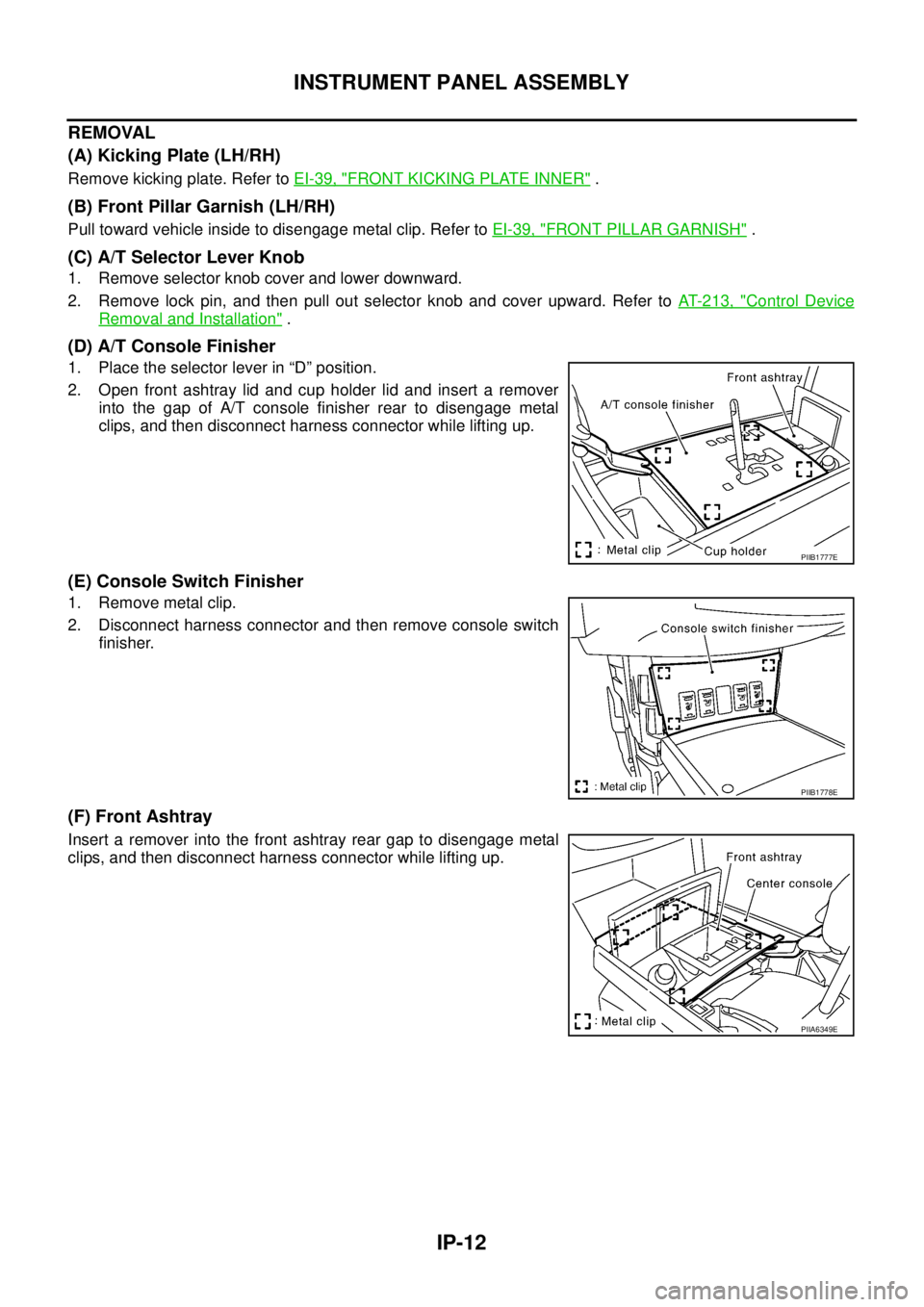
(A) Kicking Plate (LH/RH)
Remove kicking plate. Refer to EI-39, "FRONT KICKING PLATE INNER" .
(B) Front Pillar Garnish (LH/RH)
Pull toward vehicle inside to disengage metal clip. Refer to EI-39, "FRONT PILLAR GARNISH" .
(C) A/T Selector Lever Knob
1. Remove selector knob cover and lower downward.
2. Remove lock pin, and then pull out selector knob and cover upward. Refer to AT- 2 1 3 , "
Control Device
Removal and Installation" .
(D) A/T Console Finisher
1. Place the selector lever in “D” position.
2. Open front ashtray lid and cup holder lid and insert a remover
into the gap of A/T console finisher rear to disengage metal
clips, and then disconnect harness connector while lifting up.
(E) Console Switch Finisher
1. Remove metal clip.
2. Disconnect harness connector and then remove console switch
finisher.
(F) Front Ashtray
Insert a remover into the front ashtray rear gap to disengage metal
clips, and then disconnect harness connector while lifting up.
PIIB1777E
PIIB1778E
PIIA6349E
Page 2595 of 3502
INSTRUMENT PANEL ASSEMBLY
IP-13
C
D
E
F
G
H
J
K
L
MA
B
IP
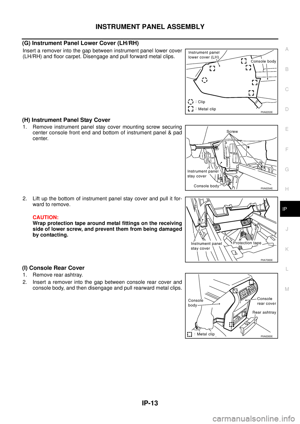
(G) Instrument Panel Lower Cover (LH/RH)
Insert a remover into the gap between instrument panel lower cover
(LH/RH) and floor carpet. Disengage and pull forward metal clips.
(H) Instrument Panel Stay Cover
1. Remove instrument panel stay cover mounting screw securing
center console front end and bottom of instrument panel & pad
center.
2. Lift up the bottom of instrument panel stay cover and pull it for-
ward to remove.
CAUTION:
Wrap protection tape around metal fittings on the receiving
side of lower screw, and prevent them from being damaged
by contacting.
(I) Console Rear Cover
1. Remove rear ashtray.
2. Insert a remover into the gap between console rear cover and
console body, and then disengage and pull rearward metal clips.
PIIA6353E
PIIA6354E
PIIA7083E
PIIA6365E
Page 2596 of 3502
IP-14
INSTRUMENT PANEL ASSEMBLY
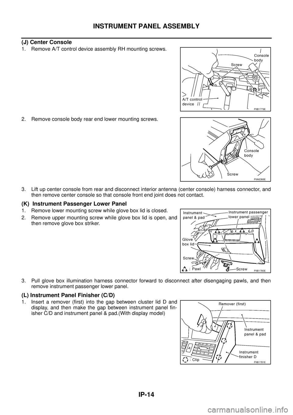
(J) Center Console
1. Remove A/T control device assembly RH mounting screws.
2. Remove console body rear end lower mounting screws.
3. Lift up center console from rear and disconnect interior antenna (center console) harness connector, and
then remove center console so that console front end joint does not contact.
(K) Instrument Passenger Lower Panel
1. Remove lower mounting screw while glove box lid is closed.
2. Remove upper mounting screw while glove box lid is open, and
then remove glove box striker.
3. Pull glove box illumination harness connector forward to disconnect after disengaging pawls, and then
remove instrument passenger lower panel.
(L) Instrument Panel Finisher (C/D)
1. Insert a remover (first) into the gap between cluster lid D and
display, and then make the gap between instrument panel fin-
isher C/D and instrument panel & pad.(With display model)
PIIB1779E
PIIA6366E
PIIB1780E
PIIB1781E
Page 2597 of 3502
INSTRUMENT PANEL ASSEMBLY
IP-15
C
D
E
F
G
H
J
K
L
MA
B
IP
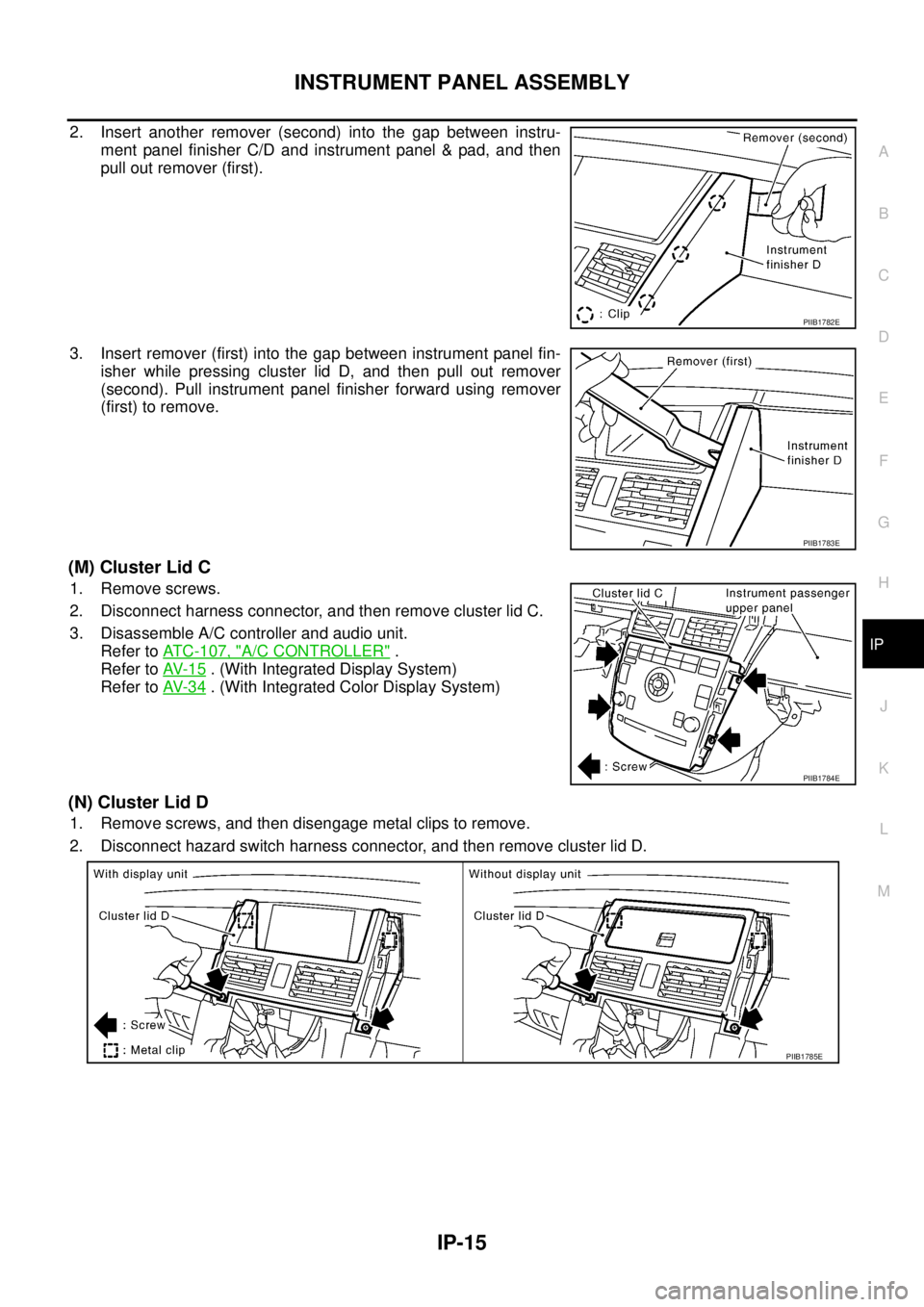
2. Insert another remover (second) into the gap between instru-
ment panel finisher C/D and instrument panel & pad, and then
pull out remover (first).
3. Insert remover (first) into the gap between instrument panel fin-
isher while pressing cluster lid D, and then pull out remover
(second). Pull instrument panel finisher forward using remover
(first) to remove.
(M) Cluster Lid C
1. Remove screws.
2. Disconnect harness connector, and then remove cluster lid C.
3. Disassemble A/C controller and audio unit.
Refer to ATC-107, "
A/C CONTROLLER" .
Refer to AV- 1 5
. (With Integrated Display System)
Refer to AV- 3 4
. (With Integrated Color Display System)
(N) Cluster Lid D
1. Remove screws, and then disengage metal clips to remove.
2. Disconnect hazard switch harness connector, and then remove cluster lid D.
PIIB1782E
PIIB1783E
PIIB1784E
PIIB1785E
Page 2598 of 3502
IP-16
INSTRUMENT PANEL ASSEMBLY
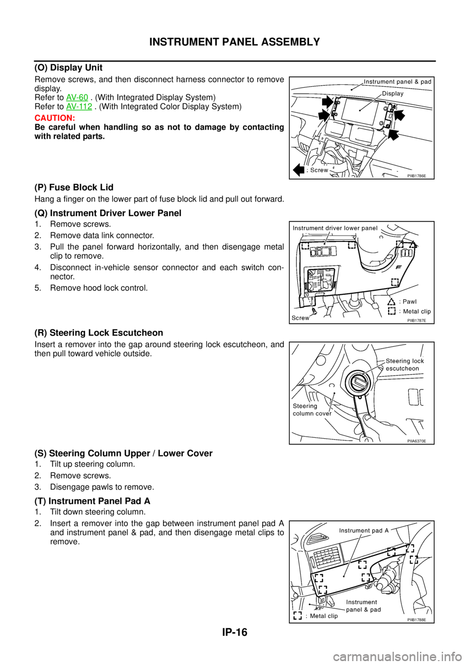
(O) Display Unit
Remove screws, and then disconnect harness connector to remove
display.
Refer to AV- 6 0
. (With Integrated Display System)
Refer to AV- 11 2
. (With Integrated Color Display System)
CAUTION:
Be careful when handling so as not to damage by contacting
with related parts.
(P) Fuse Block Lid
Hang a finger on the lower part of fuse block lid and pull out forward.
(Q) Instrument Driver Lower Panel
1. Remove screws.
2. Remove data link connector.
3. Pull the panel forward horizontally, and then disengage metal
clip to remove.
4. Disconnect in-vehicle sensor connector and each switch con-
nector.
5. Remove hood lock control.
(R) Steering Lock Escutcheon
Insert a remover into the gap around steering lock escutcheon, and
then pull toward vehicle outside.
(S) Steering Column Upper / Lower Cover
1. Tilt up steering column.
2. Remove screws.
3. Disengage pawls to remove.
(T) Instrument Panel Pad A
1. Tilt down steering column.
2. Insert a remover into the gap between instrument panel pad A
and instrument panel & pad, and then disengage metal clips to
remove.
PIIB1786E
PIIB1787E
PIIA6370E
PIIB1788E
Page 2599 of 3502
INSTRUMENT PANEL ASSEMBLY
IP-17
C
D
E
F
G
H
J
K
L
MA
B
IP
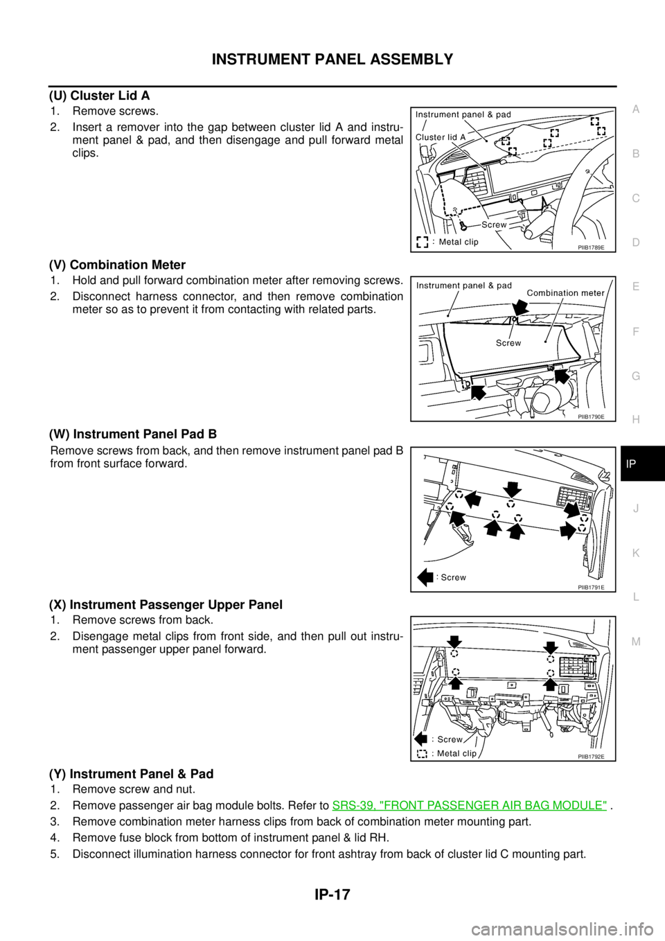
(U) Cluster Lid A
1. Remove screws.
2. Insert a remover into the gap between cluster lid A and instru-
ment panel & pad, and then disengage and pull forward metal
clips.
(V) Combination Meter
1. Hold and pull forward combination meter after removing screws.
2. Disconnect harness connector, and then remove combination
meter so as to prevent it from contacting with related parts.
(W) Instrument Panel Pad B
Remove screws from back, and then remove instrument panel pad B
from front surface forward.
(X) Instrument Passenger Upper Panel
1. Remove screws from back.
2. Disengage metal clips from front side, and then pull out instru-
ment passenger upper panel forward.
(Y) Instrument Panel & Pad
1. Remove screw and nut.
2. Remove passenger air bag module bolts. Refer to SRS-39, "
FRONT PASSENGER AIR BAG MODULE" .
3. Remove combination meter harness clips from back of combination meter mounting part.
4. Remove fuse block from bottom of instrument panel & lid RH.
5. Disconnect illumination harness connector for front ashtray from back of cluster lid C mounting part.
PIIB1789E
PIIB1790E
PIIB1791E
PIIB1792E
Page 2600 of 3502

IP-18
INSTRUMENT PANEL ASSEMBLY
6. Disconnect sunload sensor, auto light sensor, and security indicator harness connectors. Refer to AT C -
111 , "SUNLOAD SENSOR" and LT- 7 4 , "Removal and Installation for Optical Sensor" .
7. Remove instrument panel & pad from passenger side door opening.
8. Remove screws, and then remove instrument panel pad from instrument panel.
(Z) Instrument Center Lower Panel
1. Remove screws from back of instrument panel & pad.
2. Remove instrument center lower panel forward from front side.
INSTALLATION
Install in the reverse order of removal.