NISSAN TEANA 2003 Service Manual
Manufacturer: NISSAN, Model Year: 2003, Model line: TEANA, Model: NISSAN TEANA 2003Pages: 3502, PDF Size: 74.56 MB
Page 761 of 3502
INTELLIGENT KEY SYSTEM
BL-103
C
D
E
F
G
H
J
K
L
MA
B
BL
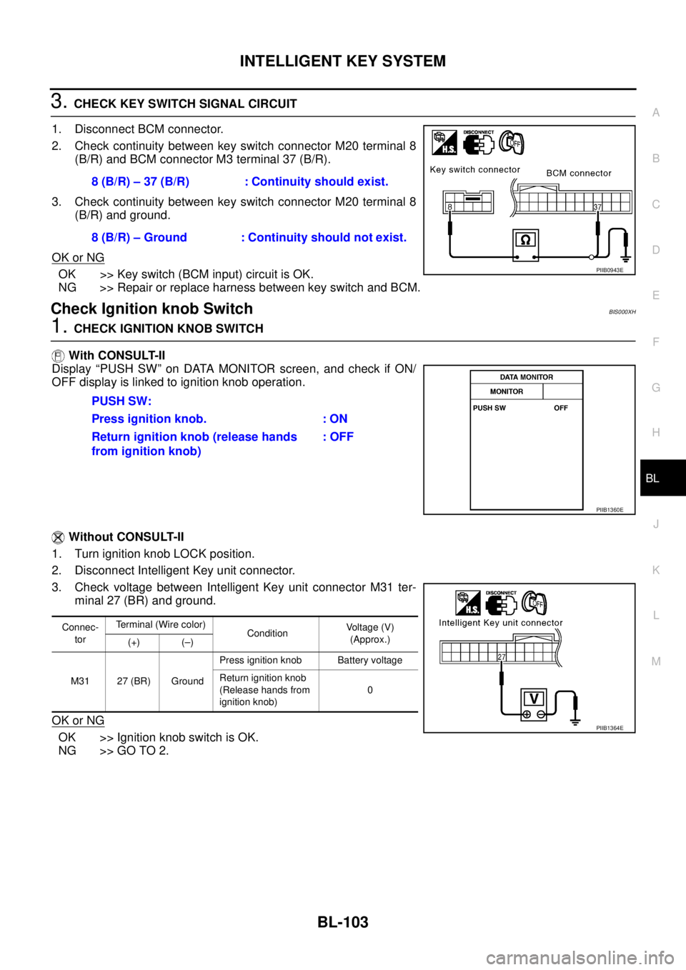
3. CHECK KEY SWITCH SIGNAL CIRCUIT
1. Disconnect BCM connector.
2. Check continuity between key switch connector M20 terminal 8
(B/R) and BCM connector M3 terminal 37 (B/R).
3. Check continuity between key switch connector M20 terminal 8
(B/R) and ground.
OK or NG
OK >> Key switch (BCM input) circuit is OK.
NG >> Repair or replace harness between key switch and BCM.
Check Ignition knob SwitchBIS000XH
1. CHECK IGNITION KNOB SWITCH
With CONSULT-II
Display “PUSH SW” on DATA MONITOR screen, and check if ON/
OFF display is linked to ignition knob operation.
Without CONSULT-II
1. Turn ignition knob LOCK position.
2. Disconnect Intelligent Key unit connector.
3. Check voltage between Intelligent Key unit connector M31 ter-
minal 27 (BR) and ground.
OK or NG
OK >> Ignition knob switch is OK.
NG >> GO TO 2.8 (B/R) – 37 (B/R) : Continuity should exist.
8 (B/R) – Ground : Continuity should not exist.
PIIB0943E
PUSH SW:
Press ignition knob. : ON
Return ignition knob (release hands
from ignition knob): OFF
PIIB1360E
Connec-
torTerminal (Wire color)
ConditionVoltage (V)
(Approx.)
(+) (–)
M31 27 (BR) GroundPress ignition knob Battery voltage
Return ignition knob
(Release hands from
ignition knob)0
PIIB1364E
Page 762 of 3502
BL-104
INTELLIGENT KEY SYSTEM
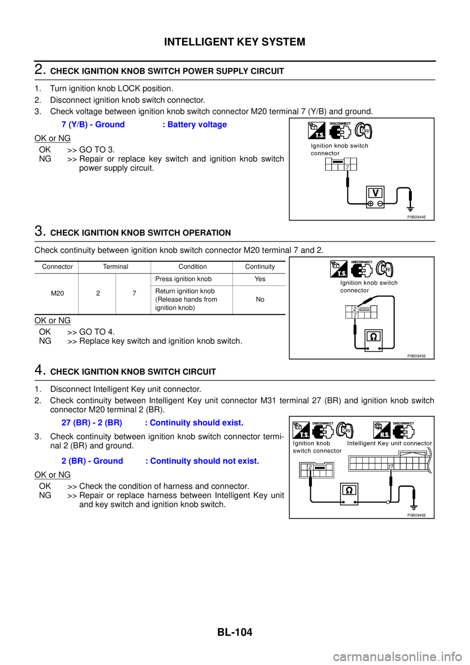
2. CHECK IGNITION KNOB SWITCH POWER SUPPLY CIRCUIT
1. Turn ignition knob LOCK position.
2. Disconnect ignition knob switch connector.
3. Check voltage between ignition knob switch connector M20 terminal 7 (Y/B) and ground.
OK or NG
OK >> GO TO 3.
NG >> Repair or replace key switch and ignition knob switch
power supply circuit.
3. CHECK IGNITION KNOB SWITCH OPERATION
Check continuity between ignition knob switch connector M20 terminal 7 and 2.
OK or NG
OK >> GO TO 4.
NG >> Replace key switch and ignition knob switch.
4. CHECK IGNITION KNOB SWITCH CIRCUIT
1. Disconnect Intelligent Key unit connector.
2. Check continuity between Intelligent Key unit connector M31 terminal 27 (BR) and ignition knob switch
connector M20 terminal 2 (BR).
3. Check continuity between ignition knob switch connector termi-
nal 2 (BR) and ground.
OK or NG
OK >> Check the condition of harness and connector.
NG >> Repair or replace harness between Intelligent Key unit
and key switch and ignition knob switch. 7 (Y/B) - Ground : Battery voltage
PIIB0944E
Connector Terminal Condition Continuity
M20 2 7Press ignition knob Yes
Return ignition knob
(Release hands from
ignition knob)No
PIIB0945E
27 (BR) - 2 (BR) : Continuity should exist.
2 (BR) - Ground : Continuity should not exist.
PIIB0946E
Page 763 of 3502
INTELLIGENT KEY SYSTEM
BL-105
C
D
E
F
G
H
J
K
L
MA
B
BL
Check Door SwitchBIS000XI
CHECK DOOR SWITCH (EXCEPT TRUNK ROOM LAMP SWITCH)
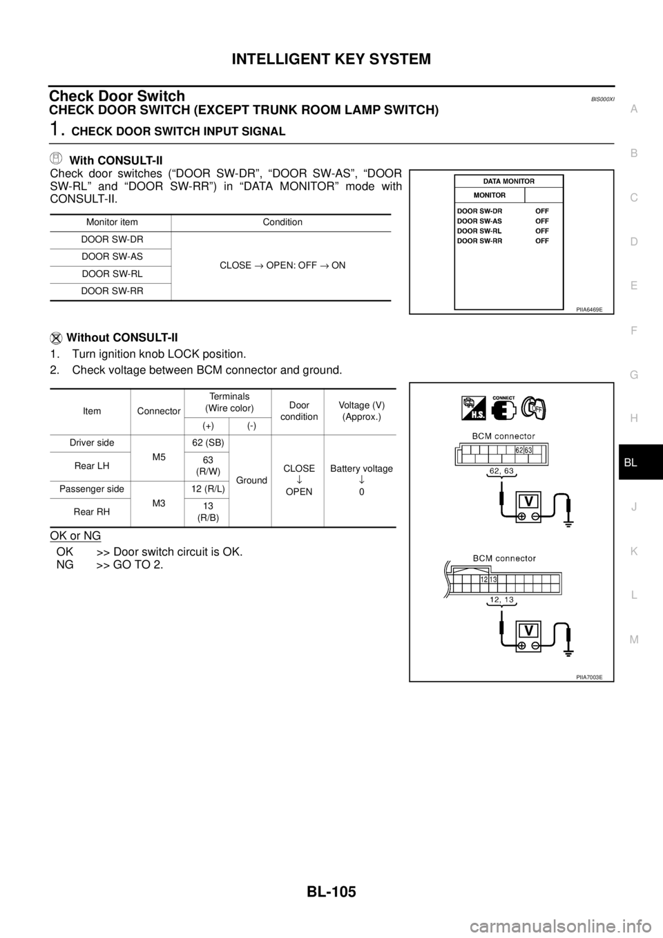
1. CHECK DOOR SWITCH INPUT SIGNAL
With CONSULT-II
Check door switches (“DOOR SW-DR”, “DOOR SW-AS”, “DOOR
SW-RL” and “DOOR SW-RR”) in “DATA MONITOR” mode with
CONSULT-II.
Without CONSULT-II
1. Turn ignition knob LOCK position.
2. Check voltage between BCM connector and ground.
OK or NG
OK >> Door switch circuit is OK.
NG >> GO TO 2.
Monitor item Condition
DOOR SW-DR
CLOSE → OPEN: OFF → ON DOOR SW-AS
DOOR SW-RL
DOOR SW-RR
Item ConnectorTerminals
(Wire color)Door
conditionVoltage (V)
(Approx.)
(+) (-)
Driver side
M562 (SB)
GroundCLOSE
↓
OPENBattery voltage
↓
0 Rear LH 63
(R/W)
Passenger side
M312 (R/L)
Rear RH13
(R/B)
PIIA6469E
PIIA7003E
Page 764 of 3502
BL-106
INTELLIGENT KEY SYSTEM
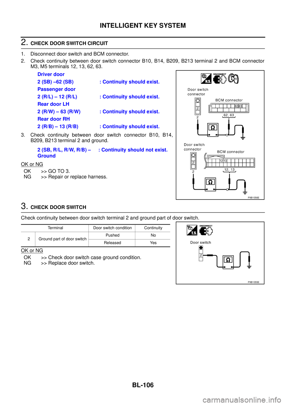
2. CHECK DOOR SWITCH CIRCUIT
1. Disconnect door switch and BCM connector.
2. Check continuity between door switch connector B10, B14, B209, B213 terminal 2 and BCM connector
M3, M5 terminals 12, 13, 62, 63.
3. Check continuity between door switch connector B10, B14,
B209, B213 terminal 2 and ground.
OK or NG
OK >> GO TO 3.
NG >> Repair or replace harness.
3. CHECK DOOR SWITCH
Check continuity between door switch terminal 2 and ground part of door switch.
OK or NG
OK >> Check door switch case ground condition.
NG >> Replace door switch.Driver door
2 (SB) –62 (SB) : Continuity should exist.
Passenger door
2 (R/L) – 12 (R/L) : Continuity should exist.
Rear door LH
2 (R/W) – 63 (R/W) : Continuity should exist.
Rear door RH
2 (R/B) – 13 (R/B) : Continuity should exist.
2 (SB, R/L, R/W, R/B) –
Ground: Continuity should not exist.
PIIB1056E
Terminal Door switch condition Continuity
2 Ground part of door switchPushed No
Released Yes
PIIB1055E
Page 765 of 3502
INTELLIGENT KEY SYSTEM
BL-107
C
D
E
F
G
H
J
K
L
MA
B
BL
CHECK TRUNK ROOM LAMP SWITCH
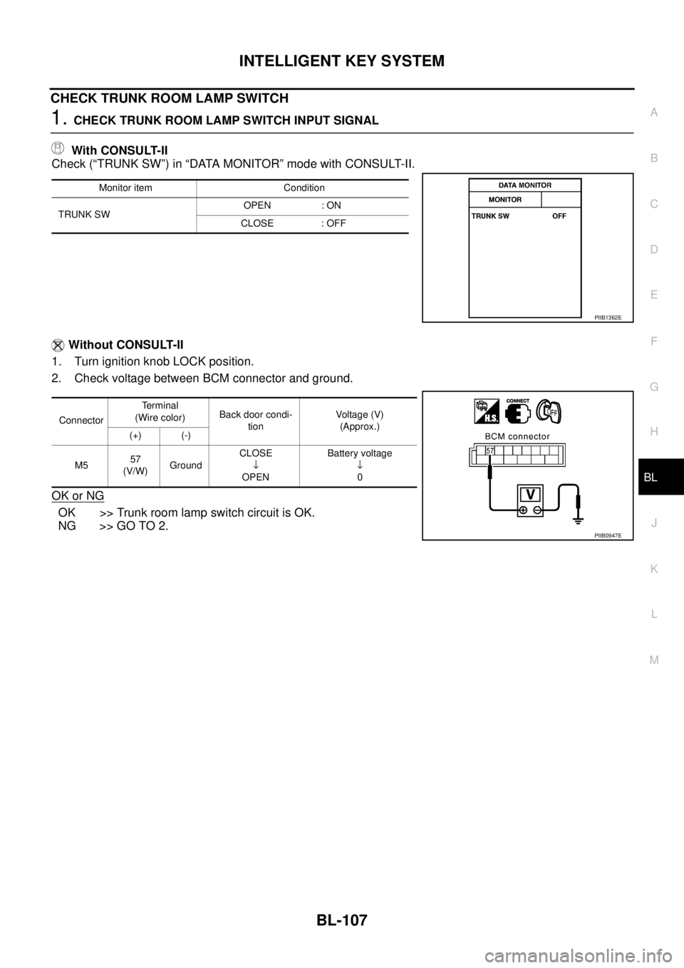
1. CHECK TRUNK ROOM LAMP SWITCH INPUT SIGNAL
With CONSULT-II
Check (“TRUNK SW”) in “DATA MONITOR” mode with CONSULT-II.
Without CONSULT-II
1. Turn ignition knob LOCK position.
2. Check voltage between BCM connector and ground.
OK or NG
OK >> Trunk room lamp switch circuit is OK.
NG >> GO TO 2.
Monitor item Condition
TRUNK SWOPEN : ON
CLOSE : OFF
PIIB1362E
ConnectorTe r m i n a l
(Wire color)Back door condi-
tionVoltage (V)
(Approx.)
(+) (-)
M557
(V/W)GroundCLOSE
↓
OPENBattery voltage
↓
0
PIIB0947E
Page 766 of 3502
BL-108
INTELLIGENT KEY SYSTEM
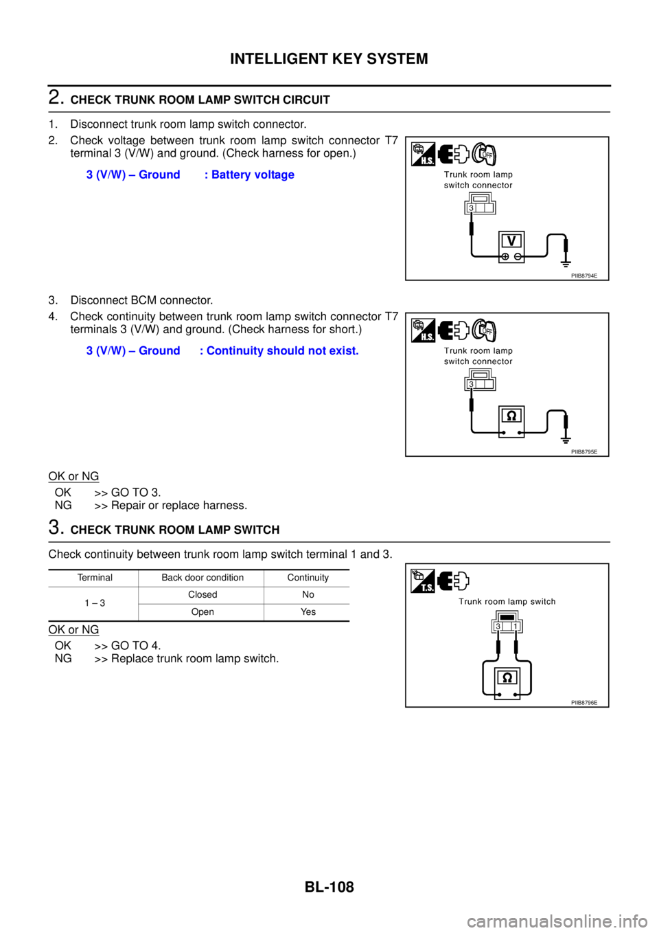
2. CHECK TRUNK ROOM LAMP SWITCH CIRCUIT
1. Disconnect trunk room lamp switch connector.
2. Check voltage between trunk room lamp switch connector T7
terminal 3 (V/W) and ground. (Check harness for open.)
3. Disconnect BCM connector.
4. Check continuity between trunk room lamp switch connector T7
terminals 3 (V/W) and ground. (Check harness for short.)
OK or NG
OK >> GO TO 3.
NG >> Repair or replace harness.
3. CHECK TRUNK ROOM LAMP SWITCH
Check continuity between trunk room lamp switch terminal 1 and 3.
OK or NG
OK >> GO TO 4.
NG >> Replace trunk room lamp switch.3 (V/W) – Ground : Battery voltage
PIIB8794E
3 (V/W) – Ground : Continuity should not exist.
PIIB8795E
Terminal Back door condition Continuity
1 – 3Closed No
Open Yes
PIIB8796E
Page 767 of 3502
INTELLIGENT KEY SYSTEM
BL-109
C
D
E
F
G
H
J
K
L
MA
B
BL
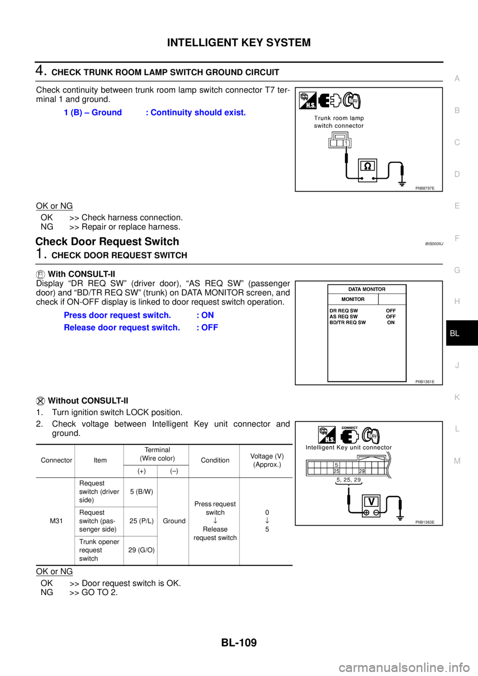
4. CHECK TRUNK ROOM LAMP SWITCH GROUND CIRCUIT
Check continuity between trunk room lamp switch connector T7 ter-
minal 1 and ground.
OK or NG
OK >> Check harness connection.
NG >> Repair or replace harness.
Check Door Request SwitchBIS000XJ
1. CHECK DOOR REQUEST SWITCH
With CONSULT-II
Display “DR REQ SW” (driver door), “AS REQ SW” (passenger
door) and “BD/TR REQ SW” (trunk) on DATA MONITOR screen, and
check if ON-OFF display is linked to door request switch operation.
Without CONSULT-II
1. Turn ignition switch LOCK position.
2. Check voltage between Intelligent Key unit connector and
ground.
OK or NG
OK >> Door request switch is OK.
NG >> GO TO 2.1 (B) – Ground : Continuity should exist.
PIIB8797E
Press door request switch. : ON
Release door request switch. : OFF
PIIB1361E
Connector ItemTe r m i n a l
(Wire color)
ConditionVoltage (V)
(Approx.)
(+) (–)
M31Request
switch (driver
side)5 (B/W)
GroundPress request
switch
↓
Release
request switch0
↓
5 Request
switch (pas-
senger side)25 (P/L)
Trunk opener
request
switch29 (G/O)
PIIB1363E
Page 768 of 3502
BL-110
INTELLIGENT KEY SYSTEM
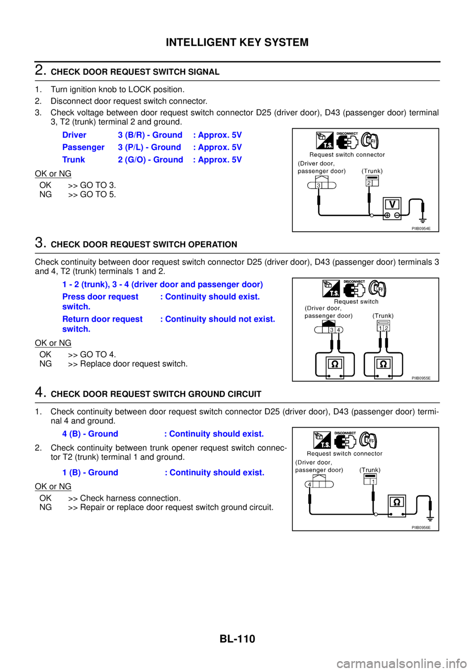
2. CHECK DOOR REQUEST SWITCH SIGNAL
1. Turn ignition knob to LOCK position.
2. Disconnect door request switch connector.
3. Check voltage between door request switch connector D25 (driver door), D43 (passenger door) terminal
3, T2 (trunk) terminal 2 and ground.
OK or NG
OK >> GO TO 3.
NG >> GO TO 5.
3. CHECK DOOR REQUEST SWITCH OPERATION
Check continuity between door request switch connector D25 (driver door), D43 (passenger door) terminals 3
and 4, T2 (trunk) terminals 1 and 2.
OK or NG
OK >> GO TO 4.
NG >> Replace door request switch.
4. CHECK DOOR REQUEST SWITCH GROUND CIRCUIT
1. Check continuity between door request switch connector D25 (driver door), D43 (passenger door) termi-
nal 4 and ground.
2. Check continuity between trunk opener request switch connec-
tor T2 (trunk) terminal 1 and ground.
OK or NG
OK >> Check harness connection.
NG >> Repair or replace door request switch ground circuit.Driver 3 (B/R) - Ground : Approx. 5V
Passenger 3 (P/L) - Ground : Approx. 5V
Trunk 2 (G/O) - Ground : Approx. 5V
PIIB0954E
1 - 2 (trunk), 3 - 4 (driver door and passenger door)
Press door request
switch.: Continuity should exist.
Return door request
switch.: Continuity should not exist.
PIIB0955E
4 (B) - Ground : Continuity should exist.
1 (B) - Ground : Continuity should exist.
PIIB0956E
Page 769 of 3502
INTELLIGENT KEY SYSTEM
BL-111
C
D
E
F
G
H
J
K
L
MA
B
BL
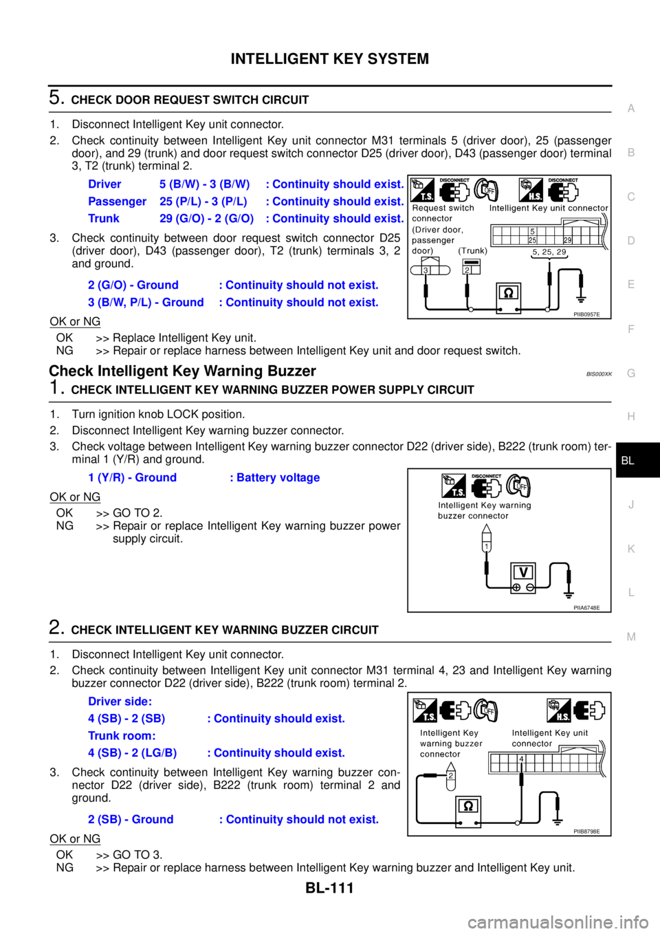
5. CHECK DOOR REQUEST SWITCH CIRCUIT
1. Disconnect Intelligent Key unit connector.
2. Check continuity between Intelligent Key unit connector M31 terminals 5 (driver door), 25 (passenger
door), and 29 (trunk) and door request switch connector D25 (driver door), D43 (passenger door) terminal
3, T2 (trunk) terminal 2.
3. Check continuity between door request switch connector D25
(driver door), D43 (passenger door), T2 (trunk) terminals 3, 2
and ground.
OK or NG
OK >> Replace Intelligent Key unit.
NG >> Repair or replace harness between Intelligent Key unit and door request switch.
Check Intelligent Key Warning BuzzerBIS000XK
1. CHECK INTELLIGENT KEY WARNING BUZZER POWER SUPPLY CIRCUIT
1. Turn ignition knob LOCK position.
2. Disconnect Intelligent Key warning buzzer connector.
3. Check voltage between Intelligent Key warning buzzer connector D22 (driver side), B222 (trunk room) ter-
minal 1 (Y/R) and ground.
OK or NG
OK >> GO TO 2.
NG >> Repair or replace Intelligent Key warning buzzer power
supply circuit.
2. CHECK INTELLIGENT KEY WARNING BUZZER CIRCUIT
1. Disconnect Intelligent Key unit connector.
2. Check continuity between Intelligent Key unit connector M31 terminal 4, 23 and Intelligent Key warning
buzzer connector D22 (driver side), B222 (trunk room) terminal 2.
3. Check continuity between Intelligent Key warning buzzer con-
nector D22 (driver side), B222 (trunk room) terminal 2 and
ground.
OK or NG
OK >> GO TO 3.
NG >> Repair or replace harness between Intelligent Key warning buzzer and Intelligent Key unit.Driver 5 (B/W) - 3 (B/W) : Continuity should exist.
Passenger 25 (P/L) - 3 (P/L) : Continuity should exist.
Trunk 29 (G/O) - 2 (G/O) : Continuity should exist.
2 (G/O) - Ground : Continuity should not exist.
3 (B/W, P/L) - Ground : Continuity should not exist.
PIIB0957E
1 (Y/R) - Ground : Battery voltage
PIIA6748E
Driver side:
4 (SB) - 2 (SB) : Continuity should exist.
Trunk room:
4 (SB) - 2 (LG/B) : Continuity should exist.
2 (SB) - Ground : Continuity should not exist.
PIIB8798E
Page 770 of 3502
BL-112
INTELLIGENT KEY SYSTEM
3. CHECK INTELLIGENT KEY WARNING BUZZER OPERATION
Connect battery power supply to Intelligent Key warning buzzer connector D22 (driver side), B222 (trunk
room) terminals 1 and 2, and check the operation.
OK or NG
OK >> Intelligent Key warning buzzer is OK.
NG >> Replace Intelligent Key warning buzzer
Check Outside Key AntennaBIS000XL
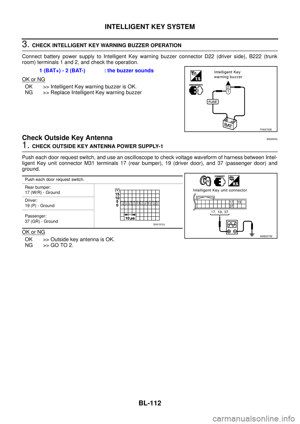
1. CHECK OUTSIDE KEY ANTENNA POWER SUPPLY-1
Push each door request switch, and use an oscilloscope to check voltage waveform of harness between Intel-
ligent Key unit connector M31 terminals 17 (rear bumper), 19 (driver door), and 37 (passenger door) and
ground.
OK or NG
OK >> Outside key antenna is OK.
NG >> GO TO 2.1 (BAT+) - 2 (BAT-) : the buzzer sounds
PIIA6750E
Push each door request switch.
Rear bumper:
17 (W/R) - Ground
Driver:
19 (P) - Ground
Passenger:
37 (GR) - Ground
MIIB0375E
SIIA1910J