interior NISSAN TEANA 2008 Owners Manual
[x] Cancel search | Manufacturer: NISSAN, Model Year: 2008, Model line: TEANA, Model: NISSAN TEANA 2008Pages: 5121, PDF Size: 69.03 MB
Page 4158 of 5121
![NISSAN TEANA 2008 Owners Manual BCM (BODY CONTROL MODULE)
SEC-149
< ECU DIAGNOSIS >[INTELLIGENT KEY SYSTEM]
C
D
E
F
G
H
I
J
L
MA
B
SEC
N
O
P
PHYSICAL VALUES
Te r m i n a l N o .
(Wire color)Description
ConditionVa l u e
(Approx.)
S](/img/5/57391/w960_57391-4157.png "NISSAN TEANA 2008 Owners Manual BCM (BODY CONTROL MODULE)
SEC-149
< ECU DIAGNOSIS >[INTELLIGENT KEY SYSTEM]
C
D
E
F
G
H
I
J
L
MA
B
SEC
N
O
P
PHYSICAL VALUES
Te r m i n a l N o .
(Wire color)Description
ConditionVa l u e
(Approx.)
S")
BCM (BODY CONTROL MODULE)
SEC-149
< ECU DIAGNOSIS >[INTELLIGENT KEY SYSTEM]
C
D
E
F
G
H
I
J
L
MA
B
SEC
N
O
P
PHYSICAL VALUES
Te r m i n a l N o .
(Wire color)Description
ConditionVa l u e
(Approx.)
Signal nameInput/
Output +–
1
(W/B)GroundBattery power sup-
plyInput Ignition switch OFF Battery voltage
2
(R/Y)GroundP/W power supply
(BAT)Output Ignition switch OFF Battery voltage
3
(L/W)GroundP/W power supply
(IGN)Output Ignition switch ON Battery voltage
4
(P/W)GroundInterior room lamp
power supplyOutputInterior room lamp battery saver is activated.
(Cuts the interior room lamp power supply)0 V
Interior room lamp battery saver is not activat-
ed.
(Outputs the interior room lamp power supply)Battery voltage
5
(G/Y)GroundPassenger door
UNLOCKOutput Passenger doorUNLOCK (Actuator is ac-
tivated)Battery voltage
Other than UNLOCK (Ac-
tuator is not activated)0 V
7
(R/W)Ground Step lamp Output Step lampON 0 V
OFF Battery voltage
8
(V)Ground All doors LOCK Output All doorsLOCK (Actuator is acti-
vated)Battery voltage
Other than LOCK (Actua-
tor is not activated)0 V
9
(G)GroundDriver door UN-
LOCKOutput Driver doorUNLOCK (Actuator is ac-
tivated)Battery voltage
Other than UNLOCK (Ac-
tuator is not activated)0 V
10
(G/Y)GroundRear RH door and
rear LH door UN-
LOCKOutputRear RH door
and rear LH doorUNLOCK (Actuator is ac-
tivated)Battery voltage
Other than UNLOCK (Ac-
tuator is not activated)0 V
11
(Y/R)GroundBattery power sup-
plyInput Ignition switch OFF Battery voltage
13
(B)
Ground Ground — Ignition switch ON 0 V
15
(Y)Ground ACC indicator lamp Output Ignition switchOFF (LOCK indicator is
not illuminated)Battery voltage
ACC or ON 0 V
17
(G/B)GroundTurn signal RH
(Front and door mir-
ror)OutputIgnition switch
ONTurn signal switch OFF 0 V
Turn signal switch RH
6.5 V
PKID0926E
Page 4159 of 5121
![NISSAN TEANA 2008 Owners Manual SEC-150
< ECU DIAGNOSIS >[INTELLIGENT KEY SYSTEM]
BCM (BODY CONTROL MODULE)
18
(G/Y)GroundTurn signal LH
(Front and door mir-
ror)OutputIgnition switch
ONTurn signal switch OFF 0 V
Turn signal switc](/img/5/57391/w960_57391-4158.png "NISSAN TEANA 2008 Owners Manual SEC-150
< ECU DIAGNOSIS >[INTELLIGENT KEY SYSTEM]
BCM (BODY CONTROL MODULE)
18
(G/Y)GroundTurn signal LH
(Front and door mir-
ror)OutputIgnition switch
ONTurn signal switch OFF 0 V
Turn signal switc")
SEC-150
< ECU DIAGNOSIS >[INTELLIGENT KEY SYSTEM]
BCM (BODY CONTROL MODULE)
18
(G/Y)GroundTurn signal LH
(Front and door mir-
ror)OutputIgnition switch
ONTurn signal switch OFF 0 V
Turn signal switch LH
6.5 V
19
(Y)GroundRoom lamp timer
controlOutputInterior room
lampOFF Battery voltage
ON 0 V
20
(G/B)GroundTurn signal RH
(Rear)OutputIgnition switch
ONTurn signal switch OFF 0 V
Turn signal switch RH
6.5 V
23
(R)Ground Trunk lid opening Output Trunk lidOPEN (Trunk lid opener
actuator is activated)Battery voltage
Other than OPEN (Trunk
lid opener actuator is not
activated)0 V
24
(G)Ground Rear fog lamp Output Rear fog lampOFF 0 V
ON Battery voltage
25
(G/Y)GroundTurn signal LH
(Rear)OutputIgnition switch
ONTurn signal switch OFF 0 V
Turn signal switch LH
6.5 V
30
(V/W)Ground Trunk room lamp Output Trunk room lampOFF 0 V
ON Battery voltage Te r m i n a l N o .
(Wire color)Description
ConditionVa l u e
(Approx.)
Signal nameInput/
Output +–
PKID0926E
PKID0926E
PKID0926E
Page 4240 of 5121
SR-26
< ON-VEHICLE REPAIR >
DISPOSAL OF AIR BAG MODULE AND SEAT BELT PRE-TENSIONER
*: If this lamp glows red, the tool is connected to the battery incorrectly. Reverse the connections and check the lamp glows green.
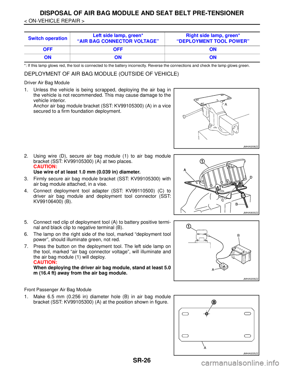
DEPLOYMENT OF AIR BAG MODULE (OUTSIDE OF VEHICLE)
Driver Air Bag Module
1. Unless the vehicle is being scrapped, deploying the air bag in
the vehicle is not recommended. This may cause damage to the
vehicle interior.
Anchor air bag module bracket (SST: KV99105300) (A) in a vice
secured to a firm foundation deployment.
2. Using wire (D), secure air bag module (1) to air bag module
bracket (SST: KV99105300) (A) at two places.
CAUTION:
Use wire of at least 1.0 mm (0.039 in) diameter.
3. Firmly secure air bag module bracket (SST: KV99105300) with
air bag module attached, in a vise.
4. Connect deployment tool adapter (SST: KV99110500) (C) to
driver air bag module and deployment tool connector (SST:
KV99106400) (B).
5. Connect red clip of deployment tool (A) to battery positive termi-
nal and black clip to negative terminal (B).
6. The lamp on the right side of the tool, marked “deployment tool
power”, should illuminate green, not red.
7. Press the button on the deployment tool. The left side lamp on
the tool, marked “air bag connector voltage”, will illuminate and
the air bag module (1) will deploy.
CAUTION:
When deploying the driver air bag module, stand at least 5.0
m (16.4 ft) away from the air bag module.
Front Passenger Air Bag Module
1. Make 6.5 mm (0.256 in) diameter hole (B) in air bag module
bracket (SST: KV99105300) (A) at the position shown in figure. Switch operationLeft side lamp, green*
“AIR BAG CONNECTOR VOLTAGE”Right side lamp, green*
“DEPLOYMENT TOOL POWER”
OFF OFF ON
ON ON ON
JMHIA0208ZZ
JMHIA0630ZZ
JMHIA0209ZZ
JMHIA0225ZZ
Page 4826 of 5121
![NISSAN TEANA 2008 Owners Manual FLUORESCENT LEAK DETECTOR
VTL-15
< PRECAUTION >[WITHOUT 7 INCH DISPLAY]
C
D
E
F
G
H
J
K
L
MA
B
VTL
N
O
P
FLUORESCENT LEAK DETECTOR
General PrecautionsINFOID:0000000003802526
CAUTION:
The A/C system](/img/5/57391/w960_57391-4825.png "NISSAN TEANA 2008 Owners Manual FLUORESCENT LEAK DETECTOR
VTL-15
< PRECAUTION >[WITHOUT 7 INCH DISPLAY]
C
D
E
F
G
H
J
K
L
MA
B
VTL
N
O
P
FLUORESCENT LEAK DETECTOR
General PrecautionsINFOID:0000000003802526
CAUTION:
The A/C system")
FLUORESCENT LEAK DETECTOR
VTL-15
< PRECAUTION >[WITHOUT 7 INCH DISPLAY]
C
D
E
F
G
H
J
K
L
MA
B
VTL
N
O
P
FLUORESCENT LEAK DETECTOR
General PrecautionsINFOID:0000000003802526
CAUTION:
The A/C system contains a fluorescent leak detection dye used for locating refrigerant leakages. An
ultraviolet (UV) lamp is required to illuminate the dye when inspecting for leakages.
Wear always fluorescence enhancing UV safety goggles to protect eyes and enhance the visibility of
the fluorescent dye.
The fluorescent dye leak detector is not a replacement for an electrical leak detector (SST). The fluo-
rescent dye leak detector should be used in conjunction with an electrical leak detector (SST) to pin-
point refrigerant leakages.
Read and follow all manufacture’s operating instructions and precautions prior to performing the
work for the purpose of safety and customer’s satisfaction.
A compressor shaft seal should not necessarily be repaired because of dye seepage. The compres-
sor shaft seal should only be repaired after confirming the leakage with an electrical leak detector
(SST).
Remove always any remaining dye from the leakage area after repairs are completed to avoid a mis-
diagnosis during a future service.
Never allow dye to come into contact with painted body panels or interior components. Clean imme-
diately with the approved dye cleaner if dye is spilled. Fluorescent dye left on a surface for an
extended period of time cannot be removed.
Never spray the fluorescent dye cleaning agent on hot surfaces (engine exhaust manifold, etc.).
Never use more than one refrigerant dye bottle (1/4 ounce /7.4 cc) per A/C system.
Leak detection dyes for HFC-134a (R-134a) and CFC-12 (R-12) A/C systems are different. Never use
HFC-134a (R-134a) leak detection dye in CFC-12 (R-12) A/C system, or CFC-12 (R-12) leak detection
dye in HFC-134a (R-134a) A/C system, or A/C system damage may result.
The fluorescent properties of the dye remains for three or more years unless a compressor malfunc-
tion occurs.
IDENTIFICATION
NOTE:
Vehicles with factory installed fluorescent dye have a green label.
Vehicles without factory installed fluorescent dye have a blue label.
IDENTIFICATION LABEL FOR VEHICLE
Vehicles with factory installed fluorescent dye have the identification label on the front side of hood.
Page 4883 of 5121
![NISSAN TEANA 2008 Owners Manual VTL-72
< PRECAUTION >[WITH 7 INCH DISPLAY]
FLUORESCENT LEAK DETECTOR
FLUORESCENT LEAK DETECTOR
General PrecautionsINFOID:0000000003894454
CAUTION:
The A/C system contains a fluorescent leak detectio](/img/5/57391/w960_57391-4882.png "NISSAN TEANA 2008 Owners Manual VTL-72
< PRECAUTION >[WITH 7 INCH DISPLAY]
FLUORESCENT LEAK DETECTOR
FLUORESCENT LEAK DETECTOR
General PrecautionsINFOID:0000000003894454
CAUTION:
The A/C system contains a fluorescent leak detectio")
VTL-72
< PRECAUTION >[WITH 7 INCH DISPLAY]
FLUORESCENT LEAK DETECTOR
FLUORESCENT LEAK DETECTOR
General PrecautionsINFOID:0000000003894454
CAUTION:
The A/C system contains a fluorescent leak detection dye used for locating refrigerant leakages. An
ultraviolet (UV) lamp is required to illuminate the dye when inspecting for leakages.
Wear always fluorescence enhancing UV safety goggles to protect eyes and enhance the visibility of
the fluorescent dye.
The fluorescent dye leak detector is not a replacement for an electrical leak detector (SST). The fluo-
rescent dye leak detector should be used in conjunction with an electrical leak detector (SST) to pin-
point refrigerant leakages.
Read and follow all manufacture’s operating instructions and precautions prior to performing the
work for the purpose of safety and customer’s satisfaction.
A compressor shaft seal should not necessarily be repaired because of dye seepage. The compres-
sor shaft seal should only be repaired after confirming the leakage with an electrical leak detector
(SST).
Remove always any remaining dye from the leakage area after repairs are completed to avoid a mis-
diagnosis during a future service.
Never allow dye to come into contact with painted body panels or interior components. Clean imme-
diately with the approved dye cleaner if dye is spilled. Fluorescent dye left on a surface for an
extended period of time cannot be removed.
Never spray the fluorescent dye cleaning agent on hot surfaces (engine exhaust manifold, etc.).
Never use more than one refrigerant dye bottle (1/4 ounce /7.4 cc) per A/C system.
Leak detection dyes for HFC-134a (R-134a) and CFC-12 (R-12) A/C systems are different. Never use
HFC-134a (R-134a) leak detection dye in CFC-12 (R-12) A/C system, or CFC-12 (R-12) leak detection
dye in HFC-134a (R-134a) A/C system, or A/C system damage may result.
The fluorescent properties of the dye remains for three or more years unless a compressor malfunc-
tion occurs.
IDENTIFICATION
NOTE:
Vehicles with factory installed fluorescent dye have a green label.
Vehicles without factory installed fluorescent dye have a blue label.
IDENTIFICATION LABEL FOR VEHICLE
Vehicles with factory installed fluorescent dye have the identification label on the front side of hood.
Page 4946 of 5121

WCS-16
< FUNCTION DIAGNOSIS >
DIAGNOSIS SYSTEM (BCM)
DIAGNOSIS SYSTEM (BCM)
COMMON ITEM
COMMON ITEM : CONSULT-III Function (BCM - COMMON ITEM)INFOID:0000000003838704
APPLICATION ITEM
CONSULT-III performs the following functions via CAN communication with BCM.
SYSTEM APPLICATION
BCM can perform the following functions for each system.
NOTE:
It can perform the diagnosis modes except the following for all sub system selection items.
×: Applicable item
NOTE:
*1:At model with Intelligent Key system this item is displayed, but is not used.
*2: This item is displayed, but is not used. Diagnosis mode Function Description
Work Support Changes the setting for each system function.
Self Diagnostic Result Displays the diagnosis results judged by BCM.
CAN Diag Support MonitorMonitors the reception status of CAN communication viewed from BCM. Refer to CONSULT-III opera-
tion manual.
Data Monitor The BCM input/output signals are displayed.
Active Test The signals used to activate each device are forcibly supplied from BCM.
Ecu Identification The BCM part number is displayed.
Configuration Read and save the vehicle specification.
Write the vehicle specification when replacing BCM.
System Sub system selection itemDiagnosis mode
Work Support Data Monitor Active Test
Door lock DOOR LOCK×××
Rear window defogger REAR DEFOGGER××
Warning chime BUZZER××
Interior room lamp timer INT LAMP×××
Remote keyless entry system
MULTI REMOTE ENT*
1×××
Exterior lamp HEAD LAMP×××
Wiper and washer WIPER××
Turn signal and hazard warning lamps FLASHER×××
—
AIR CONDITONER*
2
Intelligent Key system
Engine start systemINTELLIGENT KEY×××
Combination switch COMB SW×
Body control system BCM×
NVIS - NATS IMMU××
Interior room lamp battery saver BATTERY SAVER×××
Back door opener system TRUNK××
Vehicle security system THEFT ALM×××
RAP system RETAINED PWR×
Signal buffer system SIGNAL BUFFER××
TPMS TPMS (AIR PRESSURE MONITOR)×××
Page 4976 of 5121

WCS-46
< ECU DIAGNOSIS >
BCM (BODY CONTROL MODULE)
Te r m i n a l N o .
(Wire color)Description
ConditionVa l u e
(Approx.)
Signal nameInput/
Output +–
1
(W/B)GroundBattery power sup-
plyInput Ignition switch OFF Battery voltage
2
(R/Y)GroundP/W power supply
(BAT)Output Ignition switch OFF Battery voltage
3
(L/W)GroundP/W power supply
(IGN)Output Ignition switch ON Battery voltage
4
(P/W)GroundInterior room lamp
power supplyOutputInterior room lamp battery saver is activated.
(Cuts the interior room lamp power supply)0 V
Interior room lamp battery saver is not activat-
ed.
(Outputs the interior room lamp power supply)Battery voltage
5
(G/Y)GroundPassenger door
UNLOCKOutput Passenger doorUNLOCK (Actuator is ac-
tivated)Battery voltage
Other than UNLOCK (Ac-
tuator is not activated)0 V
7
(R/W)Ground Step lamp Output Step lampON 0 V
OFF Battery voltage
8
(V)Ground All doors LOCK Output All doorsLOCK (Actuator is acti-
vated)Battery voltage
Other than LOCK (Actua-
tor is not activated)0 V
9
(G)GroundDriver door UN-
LOCKOutput Driver doorUNLOCK (Actuator is ac-
tivated)Battery voltage
Other than UNLOCK (Ac-
tuator is not activated)0 V
10
(G/Y)GroundRear RH door and
rear LH door UN-
LOCKOutputRear RH door
and rear LH doorUNLOCK (Actuator is ac-
tivated)Battery voltage
Other than UNLOCK (Ac-
tuator is not activated)0 V
11
(Y/R)GroundBattery power sup-
plyInput Ignition switch OFF Battery voltage
13
(B)Ground Ground — Ignition switch ON 0 V
15
(Y)Ground ACC indicator lamp Output Ignition switchOFF (LOCK indicator is
not illuminated)Battery voltage
ACC or ON 0 V
17
(G/B)GroundTurn signal RH
(Front and door mir-
ror)OutputIgnition switch
ONTurn signal switch OFF 0 V
Turn signal switch RH
6.5 V
PKID0926E
Page 4977 of 5121
WCS
BCM (BODY CONTROL MODULE)
WCS-47
< ECU DIAGNOSIS >
C
D
E
F
G
H
I
J
K
L
MB A
O
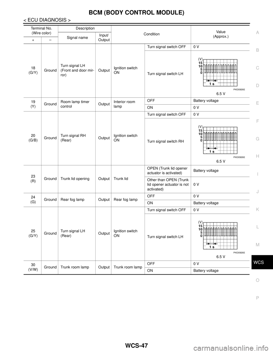
P18
(G/Y)GroundTurn signal LH
(Front and door mir-
ror)OutputIgnition switch
ONTurn signal switch OFF 0 V
Turn signal switch LH
6.5 V
19
(Y)GroundRoom lamp timer
controlOutputInterior room
lampOFF Battery voltage
ON 0 V
20
(G/B)GroundTurn signal RH
(Rear)OutputIgnition switch
ONTurn signal switch OFF 0 V
Turn signal switch RH
6.5 V
23
(R)Ground Trunk lid opening Output Trunk lidOPEN (Trunk lid opener
actuator is activated)Battery voltage
Other than OPEN (Trunk
lid opener actuator is not
activated)0 V
24
(G)Ground Rear fog lamp Output Rear fog lampOFF 0 V
ON Battery voltage
25
(G/Y)GroundTurn signal LH
(Rear)OutputIgnition switch
ONTurn signal switch OFF 0 V
Turn signal switch LH
6.5 V
30
(V/W)Ground Trunk room lamp Output Trunk room lampOFF 0 V
ON Battery voltage Te r m i n a l N o .
(Wire color)Description
ConditionVa l u e
(Approx.)
Signal nameInput/
Output +–
PKID0926E
PKID0926E
PKID0926E
Page 5024 of 5121

WW-12
< FUNCTION DIAGNOSIS >
DIAGNOSIS SYSTEM (BCM)
DIAGNOSIS SYSTEM (BCM)
COMMON ITEM
COMMON ITEM : CONSULT-III Function (BCM - COMMON ITEM)INFOID:0000000003941291
APPLICATION ITEM
CONSULT-III performs the following functions via CAN communication with BCM.
SYSTEM APPLICATION
BCM can perform the following functions for each system.
NOTE:
It can perform the diagnosis modes except the following for all sub system selection items.
×: Applicable item
NOTE:
*: This item is displayed, but is not used.
FREEZE FRAME DATA (FFD) AND IGN COUNTER
Freeze Frame Data
Diagnosis mode Function Description
Work Support Changes the setting for each system function.
Self Diagnostic Result Displays the diagnosis results judged by BCM.
CAN Diag Support MonitorMonitors the reception status of CAN communication viewed from BCM. Refer to CONSULT-III opera-
tion manual.
Data Monitor The BCM input/output signals are displayed.
Active Test The signals used to activate each device are forcibly supplied from BCM.
Ecu Identification The BCM part number is displayed.
Configuration Read and save the vehicle specification.
Write the vehicle specification when replacing BCM.
System Sub system selection itemDiagnosis mode
Work Support Data Monitor Active Test
Door lock DOOR LOCK×××
Rear window defogger REAR DEFOGGER××
Warning chime BUZZER××
Interior room lamp timer INT LAMP×××
Exterior lamp HEAD LAMP×××
Wiper and washer WIPER×××
Turn signal and hazard warning lamps FLASHER×××
— AIR CONDITONER*
Intelligent Key system
Engine start systemINTELLIGENT KEY×××
Combination switch COMB SW×
Body control system BCM×
NVIS - NATS IMMU××
Interior room lamp battery saver BATTERY SAVER×××
Trunk lid opener system TRUNK××
Vehicle security system THEFT ALM×××
— RETAINED PWR*×
Signal buffer system SIGNAL BUFFER××
— TPMS (AIR PRESSURE MONITOR)*×××
Page 5059 of 5121
BCM (BODY CONTROL MODULE)
WW-47
< ECU DIAGNOSIS >
C
D
E
F
G
H
I
J
K
MA
B
WW
N
O
P
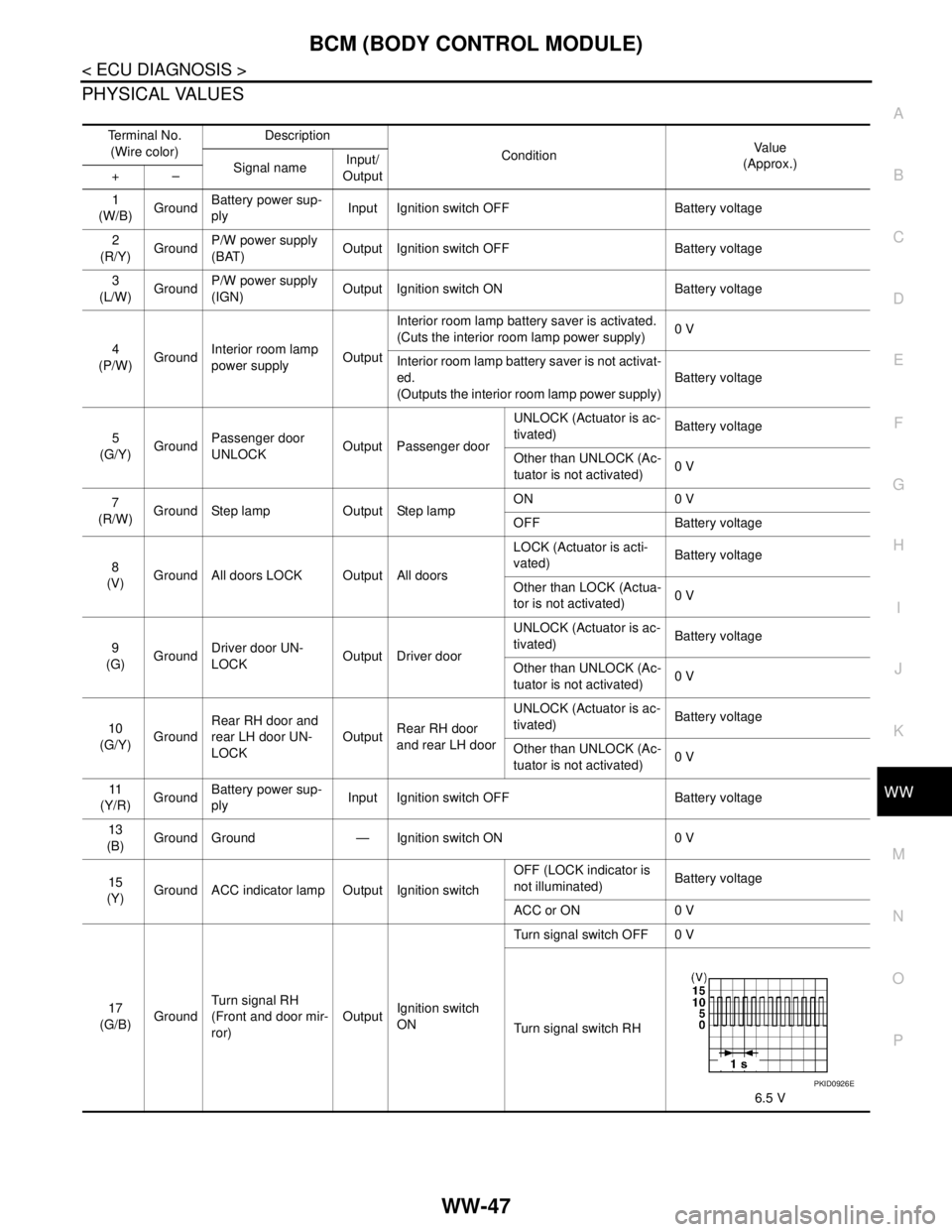
PHYSICAL VALUES
Te r m i n a l N o .
(Wire color)Description
ConditionVa l u e
(Approx.)
Signal nameInput/
Output +–
1
(W/B)GroundBattery power sup-
plyInput Ignition switch OFF Battery voltage
2
(R/Y)GroundP/W power supply
(BAT)Output Ignition switch OFF Battery voltage
3
(L/W)GroundP/W power supply
(IGN)Output Ignition switch ON Battery voltage
4
(P/W)GroundInterior room lamp
power supplyOutputInterior room lamp battery saver is activated.
(Cuts the interior room lamp power supply)0 V
Interior room lamp battery saver is not activat-
ed.
(Outputs the interior room lamp power supply)Battery voltage
5
(G/Y)GroundPassenger door
UNLOCKOutput Passenger doorUNLOCK (Actuator is ac-
tivated)Battery voltage
Other than UNLOCK (Ac-
tuator is not activated)0 V
7
(R/W)Ground Step lamp Output Step lampON 0 V
OFF Battery voltage
8
(V)Ground All doors LOCK Output All doorsLOCK (Actuator is acti-
vated)Battery voltage
Other than LOCK (Actua-
tor is not activated)0 V
9
(G)GroundDriver door UN-
LOCKOutput Driver doorUNLOCK (Actuator is ac-
tivated)Battery voltage
Other than UNLOCK (Ac-
tuator is not activated)0 V
10
(G/Y)GroundRear RH door and
rear LH door UN-
LOCKOutputRear RH door
and rear LH doorUNLOCK (Actuator is ac-
tivated)Battery voltage
Other than UNLOCK (Ac-
tuator is not activated)0 V
11
(Y/R)GroundBattery power sup-
plyInput Ignition switch OFF Battery voltage
13
(B)
Ground Ground — Ignition switch ON 0 V
15
(Y)Ground ACC indicator lamp Output Ignition switchOFF (LOCK indicator is
not illuminated)Battery voltage
ACC or ON 0 V
17
(G/B)GroundTurn signal RH
(Front and door mir-
ror)OutputIgnition switch
ONTurn signal switch OFF 0 V
Turn signal switch RH
6.5 V
PKID0926E