interior NISSAN TEANA 2008 Repair Manual
[x] Cancel search | Manufacturer: NISSAN, Model Year: 2008, Model line: TEANA, Model: NISSAN TEANA 2008Pages: 5121, PDF Size: 69.03 MB
Page 2914 of 5121
INTERIOR ROOM LAMP CONTROL SYSTEM
INL-35
< COMPONENT DIAGNOSIS >
C
D
E
F
G
H
I
J
K
MA
B
INL
N
O
P
JCLWM1481GB
Page 2915 of 5121
INL-36
< COMPONENT DIAGNOSIS >
INTERIOR ROOM LAMP CONTROL SYSTEM
JCLWM1482GB
Page 2916 of 5121
INTERIOR ROOM LAMP CONTROL SYSTEM
INL-37
< COMPONENT DIAGNOSIS >
C
D
E
F
G
H
I
J
K
MA
B
INL
N
O
P
JCLWM1483GB
Page 2917 of 5121
INL-38
< COMPONENT DIAGNOSIS >
INTERIOR ROOM LAMP CONTROL SYSTEM
JCLWM1484GB
Page 2937 of 5121

INL-58
< ECU DIAGNOSIS >
BCM (BODY CONTROL MODULE)
PHYSICAL VALUES
Te r m i n a l N o .
(Wire color)Description
ConditionVa l u e
(Approx.)
Signal nameInput/
Output +–
1
(W/B)GroundBattery power sup-
plyInput Ignition switch OFF Battery voltage
2
(R/Y)GroundP/W power supply
(BAT)Output Ignition switch OFF Battery voltage
3
(L/W)GroundP/W power supply
(IGN)Output Ignition switch ON Battery voltage
4
(P/W)GroundInterior room lamp
power supplyOutputInterior room lamp battery saver is activated.
(Cuts the interior room lamp power supply)0 V
Interior room lamp battery saver is not activat-
ed.
(Outputs the interior room lamp power supply)Battery voltage
5
(G/Y)GroundPassenger door
UNLOCKOutput Passenger doorUNLOCK (Actuator is ac-
tivated)Battery voltage
Other than UNLOCK (Ac-
tuator is not activated)0 V
7
(R/W)Ground Step lamp Output Step lampON 0 V
OFF Battery voltage
8
(V)Ground All doors LOCK Output All doorsLOCK (Actuator is acti-
vated)Battery voltage
Other than LOCK (Actua-
tor is not activated)0 V
9
(G)GroundDriver door UN-
LOCKOutput Driver doorUNLOCK (Actuator is ac-
tivated)Battery voltage
Other than UNLOCK (Ac-
tuator is not activated)0 V
10
(G/Y)GroundRear RH door and
rear LH door UN-
LOCKOutputRear RH door
and rear LH doorUNLOCK (Actuator is ac-
tivated)Battery voltage
Other than UNLOCK (Ac-
tuator is not activated)0 V
11
(Y/R)GroundBattery power sup-
plyInput Ignition switch OFF Battery voltage
13
(B)Ground Ground — Ignition switch ON 0 V
15
(Y)Ground ACC indicator lamp Output Ignition switchOFF (LOCK indicator is
not illuminated)Battery voltage
ACC or ON 0 V
17
(G/B)GroundTurn signal RH
(Front and door mir-
ror)OutputIgnition switch
ONTurn signal switch OFF 0 V
Turn signal switch RH
6.5 V
PKID0926E
Page 2938 of 5121
BCM (BODY CONTROL MODULE)
INL-59
< ECU DIAGNOSIS >
C
D
E
F
G
H
I
J
K
MA
B
INL
N
O
P
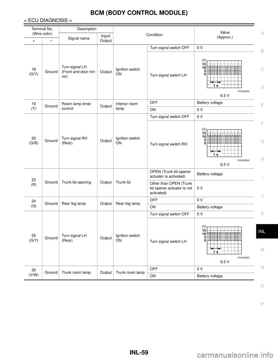
18
(G/Y)GroundTurn signal LH
(Front and door mir-
ror)OutputIgnition switch
ONTurn signal switch OFF 0 V
Turn signal switch LH
6.5 V
19
(Y)GroundRoom lamp timer
controlOutputInterior room
lampOFF Battery voltage
ON 0 V
20
(G/B)GroundTurn signal RH
(Rear)OutputIgnition switch
ONTurn signal switch OFF 0 V
Turn signal switch RH
6.5 V
23
(R)Ground Trunk lid opening Output Trunk lidOPEN (Trunk lid opener
actuator is activated)Battery voltage
Other than OPEN (Trunk
lid opener actuator is not
activated)0 V
24
(G)Ground Rear fog lamp Output Rear fog lampOFF 0 V
ON Battery voltage
25
(G/Y)GroundTurn signal LH
(Rear)OutputIgnition switch
ONTurn signal switch OFF 0 V
Turn signal switch LH
6.5 V
30
(V/W)Ground Trunk room lamp Output Trunk room lampOFF 0 V
ON Battery voltage Te r m i n a l N o .
(Wire color)Description
ConditionVa l u e
(Approx.)
Signal nameInput/
Output +–
PKID0926E
PKID0926E
PKID0926E
Page 2966 of 5121
INTERIOR LIGHTING SYSTEM SYMPTOMS
INL-87
< SYMPTOM DIAGNOSIS >
C
D
E
F
G
H
I
J
K
MA
B
INL
N
O
P
SYMPTOM DIAGNOSIS
INTERIOR LIGHTING SYSTEM SYMPTOMS
Symptom TableINFOID:0000000003774578
CAUTION:
Perform the self-diagnosis with CONSULT-III before the symptom diagnosis. Perform the trouble diag-
nosis if any DTC is detected.
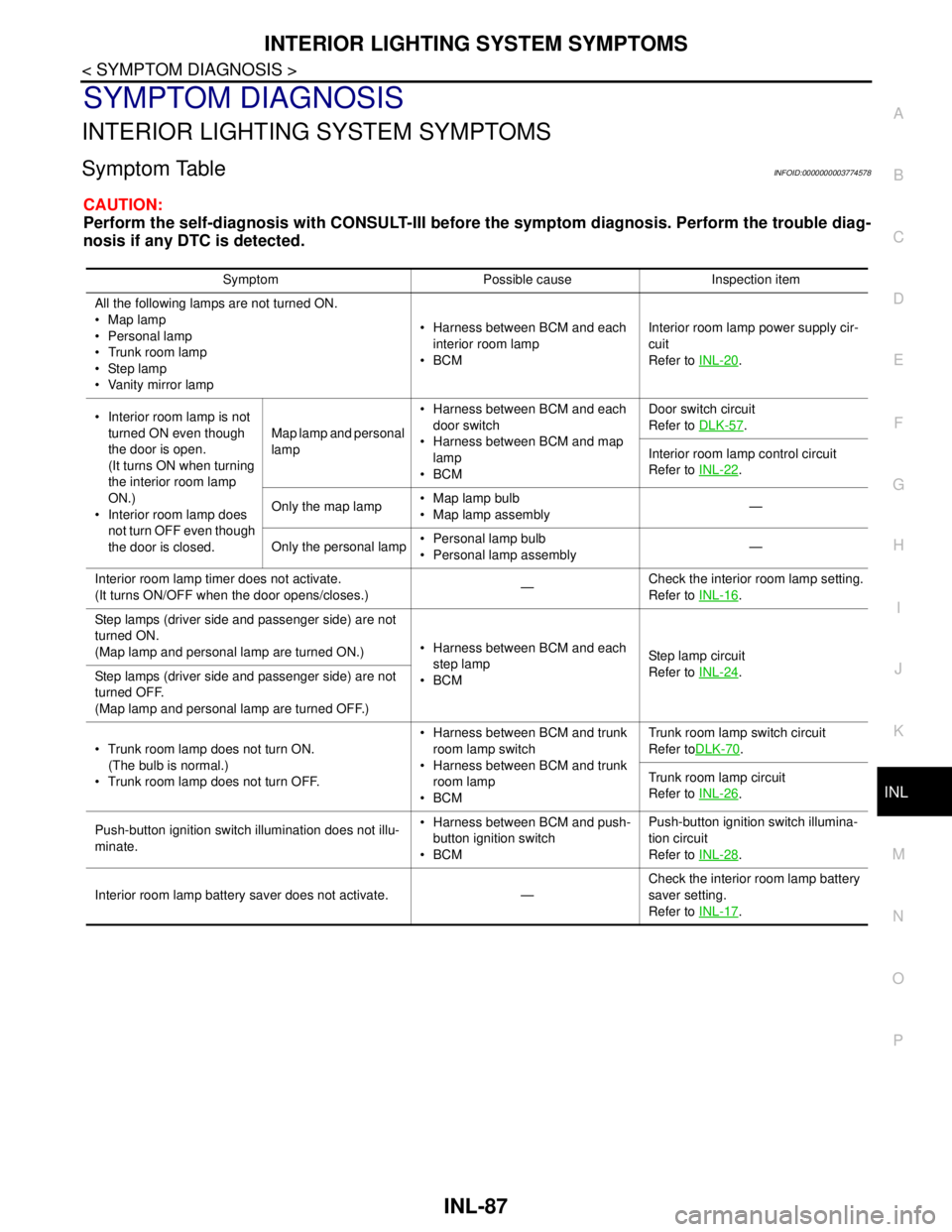
Symptom Possible cause Inspection item
All the following lamps are not turned ON.
Map lamp
Personal lamp
Trunk room lamp
Step lamp
Vanity mirror lamp Harness between BCM and each
interior room lamp
BCMInterior room lamp power supply cir-
cuit
Refer to INL-20
.
Interior room lamp is not
turned ON even though
the door is open.
(It turns ON when turning
the interior room lamp
ON.)
Interior room lamp does
not turn OFF even though
the door is closed.Map lamp and personal
lamp Harness between BCM and each
door switch
Harness between BCM and map
lamp
BCMDoor switch circuit
Refer to DLK-57
.
Interior room lamp control circuit
Refer to INL-22
.
Only the map lamp Map lamp bulb
Map lamp assembly—
Only the personal lamp Personal lamp bulb
Personal lamp assembly—
Interior room lamp timer does not activate.
(It turns ON/OFF when the door opens/closes.)—Check the interior room lamp setting.
Refer to INL-16
.
Step lamps (driver side and passenger side) are not
turned ON.
(Map lamp and personal lamp are turned ON.) Harness between BCM and each
step lamp
BCMStep lamp circuit
Refer to INL-24
.
Step lamps (driver side and passenger side) are not
turned OFF.
(Map lamp and personal lamp are turned OFF.)
Trunk room lamp does not turn ON.
(The bulb is normal.)
Trunk room lamp does not turn OFF. Harness between BCM and trunk
room lamp switch
Harness between BCM and trunk
room lamp
BCMTrunk room lamp switch circuit
Refer toDLK-70
.
Trunk room lamp circuit
Refer to INL-26
.
Push-button ignition switch illumination does not illu-
minate. Harness between BCM and push-
button ignition switch
BCMPush-button ignition switch illumina-
tion circuit
Refer to INL-28
.
Interior room lamp battery saver does not activate. —Check the interior room lamp battery
saver setting.
Refer to INL-17
.
Page 2978 of 5121

INT-1
BODY INTERIOR
C
D
E
F
G
H
I
K
L
M
SECTION INT
A
B
INT
N
O
P
CONTENTS
INTERIOR
BASIC INSPECTION ....................................3
DIAGNOSIS AND REPAIR WORKFLOW ..........3
WorkFlow ..................................................................3
FUNCTION DIAGNOSIS ...............................4
REAR SUNSHADE SYSTEM ..............................4
System Diagram ........................................................4
System Description ...................................................4
Component Parts Location ........................................4
Component Description .............................................5
COMPONENT DIAGNOSIS ..........................6
POWER SUPPLY AND GROUND CIRCUIT .......6
REAR SUNSHADE CONTROL UNIT ..........................6
REAR SUNSHADE CONTROL UNIT : Diagnosis
Procedure ..................................................................
6
REAR SUNSHADE SWITCH ..............................7
FRONT .........................................................................7
FRONT : Description .................................................7
FRONT : Component Function Check ......................7
FRONT : Diagnosis Procedure .................................7
FRONT : Component Inspection ...............................8
REAR ...........................................................................8
REAR : Description ...................................................8
REAR : Component Function Check .........................8
REAR : Diagnosis Procedure ....................................8
REAR : Component Inspection ...............................10
REAR SUNSHADE MOTOR ..............................11
Description ..............................................................11
Component Function Check ....................................11
Diagnosis Procedure ...............................................11
REVERSE SIGNAL CIRCUIT .............................12
Description ..............................................................12
Component Function Check ....................................12
Diagnosis Procedure ...............................................12
ECU DIAGNOSIS .........................................13
REAR SUNSHADE CONTROL UNIT ...............13
Reference Value ......................................................13
Wiring Diagram - REAR SUNSHADE CONTROL
SYSTEM - ................................................................
14
SYMPTOM DIAGNOSIS ..............................18
REAR SUNSHADE DOES NOT OPERATE .....18
WHEN TURNING ON REAR SUNSHADE SWITCH
(FRONT AND REAR) .................................................
18
WHEN TURNING ON REAR SUNSHADE
SWITCH (FRONT AND REAR) : Diagnosis Proce-
dure .........................................................................
18
WHEN TURNING ON REAR SUNSHADE SWITCH
(FRONT) .....................................................................
18
WHEN TURNING ON REAR SUNSHADE
SWITCH (FRONT) : Diagnosis Procedure ..............
18
WHEN TURNING ON REAR SUNSHADE SWITCH
(REAR) .......................................................................
18
WHEN TURNING ON REAR SUNSHADE
SWITCH (REAR) : Diagnosis Procedure .................
18
REAR SUNSHADE DOES NOT LOWER
WHEN SHIFT LEVER IS IN THE "R" POSI-
TION ..................................................................
20
Diagnosis Procedure ...............................................20
SQUEAK AND RATTLE TROUBLE DIAG-
NOSES ..............................................................
21
Work Flow ................................................................21
Inspection Procedure ...............................................23
Diagnostic Worksheet ..............................................25
PRECAUTION ..............................................27
PRECAUTIONS .................................................27
Page 3001 of 5121

INT-24
< SYMPTOM DIAGNOSIS >
SQUEAK AND RATTLE TROUBLE DIAGNOSES
SEATS
When isolating seat noise it is important to note the position the seat is in and the load placed on the seat
when the noise occurs. These conditions should be duplicated when verifying and isolating the cause of the
noise.
Cause of seat noise include:
1. Headrest rods and holder
2. A squeak between the seat pad cushion and frame
3. Rear seatback lock and bracket
These noises can be isolated by moving or pressing on the suspected components while duplicating the con-
ditions under which the noise occurs. Most of these incidents can be repaired by repositioning the component
or applying urethane tape to the contact area.
UNDERHOOD
Some interior noise may be caused by components under the hood or on the engine wall. The noise is then
transmitted into the passenger compartment.
Causes of transmitted underhood noise include:
1. Any component mounted to the engine wall
2. Components that pass through the engine wall
3. Engine wall mounts and connectors
4. Loose radiator mounting pins
5. Hood bumpers out of adjustment
6. Hood striker out of adjustment
These noises can be difficult to isolate since they cannot be reached from the interior of the vehicle. The best
method is to secure, move or insulate one component at a time and test drive the vehicle. Also, engine RPM
or load can be changed to isolate the noise. Repairs can usually be made by moving, adjusting, securing, or
insulating the component causing the noise.
Page 3041 of 5121

IP-1
BODY INTERIOR
C
DE
F
G H
I
K L
M
SECTION IP
A
B
IP
N
O P
CONTENTS
INSTRUMENT PANEL
SYMPTOM DIAGNOSIS ..... ..........................2
SQUEAK AND RATTLE TROUBLE DIAG-
NOSES ........................ ........................................
2
Work Flow ........................................................... ......2
Inspection Procedure ................................................4
Diagnostic Worksheet ...............................................6
PRECAUTION ...............................................8
PRECAUTIONS .............................................. .....8
Precaution for Supplemental Restraint System
(SRS) "AIR BAG" and "SEAT BELT PRE-TEN-
SIONER" ............................................................. ......
8
Precaution Necessary for Steering Wheel Rota-
tion after Battery Disconnect .....................................
8
Precaution .................................................................8
PREPARATION ...........................................10
PREPARATION .................................................10
Commercial Service Tools ................................. ....10
ON-VEHICLE REPAIR .................................11
INSTRUMENT PANEL ASSEMBLY .................11
Exploded View ..................................................... ....11
Removal and Installation .........................................12
CENTER CONSOLE ASSEMBLY ....................22
Exploded View .........................................................22
Removal and Installation .........................................22
Disassembly and Assembly .....................................26