bose amp NISSAN TEANA 2008 Service Manual
[x] Cancel search | Manufacturer: NISSAN, Model Year: 2008, Model line: TEANA, Model: NISSAN TEANA 2008Pages: 5121, PDF Size: 69.03 MB
Page 2331 of 5121
![NISSAN TEANA 2008 Service Manual EXL-302
< ECU DIAGNOSIS >[HALOGEN TYPE]
BCM (BODY CONTROL MODULE)
NOTE:
*: Without BOSE audio system145
(LG/R)GroundCombination switch
OUTPUT 3OutputCombination
switch
(Wiper intermit-
tent dial 4)A](/img/5/57391/w960_57391-2330.png "NISSAN TEANA 2008 Service Manual EXL-302
< ECU DIAGNOSIS >[HALOGEN TYPE]
BCM (BODY CONTROL MODULE)
NOTE:
*: Without BOSE audio system145
(LG/R)GroundCombination switch
OUTPUT 3OutputCombination
switch
(Wiper intermit-
tent dial 4)A")
EXL-302
< ECU DIAGNOSIS >[HALOGEN TYPE]
BCM (BODY CONTROL MODULE)
NOTE:
*: Without BOSE audio system145
(LG/R)GroundCombination switch
OUTPUT 3OutputCombination
switch
(Wiper intermit-
tent dial 4)All switch OFF 0 V
Front wiper switch INT
10.7 V Front wiper switch LO
Lighting switch AUTO
Rear fog lamp switch ON
146
(G/Y)GroundCombination switch
OUTPUT 4OutputCombination
switch
(Wiper intermit-
tent dial 4)All switch OFF 0 V
Front fog lamp switch ON
10.7 V Lighting switch 2ND
Lighting switch PASS
Turn signal switch LH
150
(SB)Ground Driver door switch Input Driver door switchOFF (When driver door
closes)
11 . 8 V
ON (When driver door
opens)0 V
151
(G/R)GroundRear window defog-
ger relayOutputRear window de-
foggerActive 0 V
Not activated Battery voltage Te r m i n a l N o .
(Wire color)Description
ConditionVa l u e
(Approx.)
Signal nameInput/
Output +–
JPMIA0034GB
JPMIA0035GB
JPMIA0011GB
Page 2820 of 5121
![NISSAN TEANA 2008 Service Manual HAC-192
< COMPONENT DIAGNOSIS >[WITH 7 INCH DISPLAY]
A/C AUTO AMP.
A/C AUTO AMP.
DescriptionINFOID:0000000003941321
COMPONENT DESCRIPTION
A/C Auto Amp. (Air Conditioner Automatic Amplifier)
The A/C au](/img/5/57391/w960_57391-2819.png "NISSAN TEANA 2008 Service Manual HAC-192
< COMPONENT DIAGNOSIS >[WITH 7 INCH DISPLAY]
A/C AUTO AMP.
A/C AUTO AMP.
DescriptionINFOID:0000000003941321
COMPONENT DESCRIPTION
A/C Auto Amp. (Air Conditioner Automatic Amplifier)
The A/C au")
HAC-192
< COMPONENT DIAGNOSIS >[WITH 7 INCH DISPLAY]
A/C AUTO AMP.
A/C AUTO AMP.
DescriptionINFOID:0000000003941321
COMPONENT DESCRIPTION
A/C Auto Amp. (Air Conditioner Automatic Amplifier)
The A/C auto amp. (1) has a built-in microcomputer that processes
information sent from various sensors needed for air conditioner
operation. The air mix door motors, the mode door motor, the intake
door motor, the blower motor and the compressor are then con-
trolled.
When the various switches and temperature control dial are oper-
ated, data is input to the A/C auto amp. from the A/C control.
Component Function CheckINFOID:0000000003940728
1.CHECK OPERATION
1. Press the AUTO switch, and then check that “AUTO” is shown on the display.
2. Operate the temperature control dial (driver side). Check that the fan speed or outlet changes. (The dis-
charge air temperature or fan speed varies depending on the ambient temperature, in-vehicle tempera-
ture, and temperature setting.)
Does it operate normally?
YES >> INSPECTION END
NO >> Perform trouble diagnosis for the A/C system. Refer to HAC-192, "
Diagnosis Procedure".
Diagnosis ProcedureINFOID:0000000003940729
1.INSPECTION BY FAIL-SAFE FUNCTION
1. Turn the ignition switch ON.
2. After approximately 30 seconds, check that the air conditioner is operated by the fail-safe function (the
operation display of air conditioner is not performed). Refer to HAC-211, "
WITHOUT INTELLIGENT AIR
CONDITIONER SYSTEM : Fail-Safe" (WITHOUT INTELLIGENT AIR CONDITIONER SYSTEM) or HAC-
223, "WITH INTELLIGENT AIR CONDITIONER SYSTEM : Fail-Safe" (WITH INTELLIGENT AIR CONDI-
TIONER SYSTEM).
Is the fail-safe function operated?
YES >> GO TO 3.
NO >> GO TO 2.
2.CHECK A/C AUTO AMP. POWER SUPPLY CIRCUIT AND GROUND
Check A/C auto amp. power supply circuit and ground circuit. Refer to HAC-192, "
Diagnosis Procedure".
Is the inspection result normal?
YES >> GO TO 3.
NO >> Repair or replace parts according to the inspection results.
3.CHECK PRESET SWITCH
Check the preset switch. Refer to AV-164, "
Symptom Table" (BASE AUDIO AND DISPLAY SYSTEM), AV-372,
"Symptom Table" (BOSE AUDIO WITHOUT NAVIGATION) or AV-640, "Symptom Table" (BOSE AUDIO WITH
NAVIGATION).
Is the inspection result normal?
YES >> Replace the A/C auto amp.
NO >> Repair or replace parts according to the inspection results.
JPIIA0894ZZ
Page 2854 of 5121
![NISSAN TEANA 2008 Service Manual HAC-226
< SYMPTOM DIAGNOSIS >[WITH 7 INCH DISPLAY]
AIR CONDITIONER CONTROL
SYMPTOM DIAGNOSIS
AIR CONDITIONER CONTROL
Diagnosis Chart By SymptomINFOID:0000000003884798
*:WITH INTELLIGENT AIR CONDITIONE](/img/5/57391/w960_57391-2853.png "NISSAN TEANA 2008 Service Manual HAC-226
< SYMPTOM DIAGNOSIS >[WITH 7 INCH DISPLAY]
AIR CONDITIONER CONTROL
SYMPTOM DIAGNOSIS
AIR CONDITIONER CONTROL
Diagnosis Chart By SymptomINFOID:0000000003884798
*:WITH INTELLIGENT AIR CONDITIONE")
HAC-226
< SYMPTOM DIAGNOSIS >[WITH 7 INCH DISPLAY]
AIR CONDITIONER CONTROL
SYMPTOM DIAGNOSIS
AIR CONDITIONER CONTROL
Diagnosis Chart By SymptomINFOID:0000000003884798
*:WITH INTELLIGENT AIR CONDITIONER SYSTEM
Symptom Reference
A/C system does not activate.Go to Trouble Diagnosis Procedure for Power Supply And
Ground Circuit.HAC-191, "
A/C AUTO AMP. :
Diagnosis Procedure"
A/C system cannot be controlled.Go to Trouble Diagnosis Procedure for Preset Switch Sys-
tem.AV- 1 6 4 , "
Symptom Table"
(DISPLAY AND AUDIO SYS-
TEM), AV- 3 7 2 , "
Symptom Ta-
ble" (BOSE AUDIO WITHOUT
NAVIGATION) or AV-640,
"Symptom Table" (BOSE AU-
DIO WITH NAVIGATION).
Air outlet does not change.
Go to Trouble Diagnosis Procedure for Mode Door Motor.
(LAN)HAC-186, "
Diagnosis Proce-
dure"Mode door motor does not operate
normally.
Discharge air temperature does not
change.
Go to Trouble Diagnosis Procedure for Air Mix Door Motor.
(LAN)HAC-182, "
Diagnosis Proce-
dure" (driver side) or HAC-184,
"Diagnosis Procedure" (pas-
senger side) Air mix door motor does not operate
normally.
Intake door does not change.
Go to Trouble Diagnosis Procedure for Intake Door Motor.
(LAN)HAC-189, "
Diagnosis Proce-
dure"Intake door motor does not operate
normally.
Blower motor operation is malfunc-
tioning.Go to Trouble Diagnosis Procedure for Blower Motor.HAC-193, "
Diagnosis Proce-
dure"
Magnet clutch does not engage. Go to Trouble Diagnosis Procedure for Magnet Clutch.HAC-197, "Diagnosis Proce-
dure"
Insufficient cooling
Go to Trouble Diagnosis Procedure for Insufficient Cooling.HAC-228, "Inspection proce-
dure"No cool air comes out.
(Air flow volume is normal.)
Insufficient heating
Go to Trouble Diagnosis Procedure for Insufficient Heating.HAC-231, "
Inspection proce-
dure"No warm air comes out.
(Air flow volume is normal.)
Noise Go to Trouble Diagnosis Procedure for Noise.HAC-234, "
Inspection proce-
dure"
Memory function does not operate. Go to Trouble Diagnosis Procedure for Memory Function.HAC-236, "Inspection proce-
dure"
Plasmacluster system does not op-
erate.*Go to Trouble Diagnosis Procedure for Plasmacluster sys-
tem.HAC-227, "
WITH INTELLI-
GENT AIR CONDITIONER
SYSTEM : Inspection proce-
dure"
Page 2954 of 5121
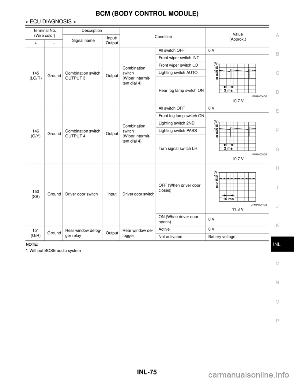
BCM (BODY CONTROL MODULE)
INL-75
< ECU DIAGNOSIS >
C
D
E
F
G
H
I
J
K
MA
B
INL
N
O
PNOTE:
*: Without BOSE audio system145
(LG/R)GroundCombination switch
OUTPUT 3OutputCombination
switch
(Wiper intermit-
tent dial 4)All switch OFF 0 V
Front wiper switch INT
10.7 V Front wiper switch LO
Lighting switch AUTO
Rear fog lamp switch ON
146
(G/Y)GroundCombination switch
OUTPUT 4OutputCombination
switch
(Wiper intermit-
tent dial 4)All switch OFF 0 V
Front fog lamp switch ON
10.7 V Lighting switch 2ND
Lighting switch PASS
Turn signal switch LH
150
(SB)Ground Driver door switch Input Driver door switchOFF (When driver door
closes)
11.8 V
ON (When driver door
opens)0 V
151
(G/R)GroundRear window defog-
ger relayOutputRear window de-
foggerActive 0 V
Not activated Battery voltage Te r m i n a l N o .
(Wire color)Description
ConditionVa l u e
(Approx.)
Signal nameInput/
Output +–
JPMIA0034GB
JPMIA0035GB
JPMIA0011GB
Page 3344 of 5121
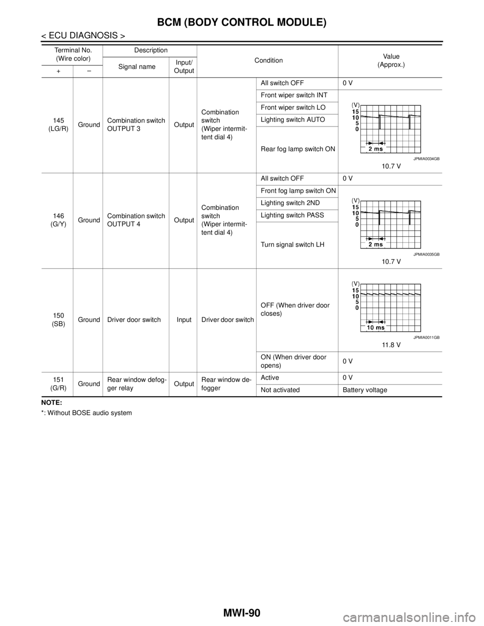
MWI-90
< ECU DIAGNOSIS >
BCM (BODY CONTROL MODULE)
NOTE:
*: Without BOSE audio system145
(LG/R)GroundCombination switch
OUTPUT 3OutputCombination
switch
(Wiper intermit-
tent dial 4)All switch OFF 0 V
Front wiper switch INT
10.7 V Front wiper switch LO
Lighting switch AUTO
Rear fog lamp switch ON
146
(G/Y)GroundCombination switch
OUTPUT 4OutputCombination
switch
(Wiper intermit-
tent dial 4)All switch OFF 0 V
Front fog lamp switch ON
10.7 V Lighting switch 2ND
Lighting switch PASS
Turn signal switch LH
150
(SB)Ground Driver door switch Input Driver door switchOFF (When driver door
closes)
11 . 8 V
ON (When driver door
opens)0 V
151
(G/R)GroundRear window defog-
ger relayOutputRear window de-
foggerActive 0 V
Not activated Battery voltage Te r m i n a l N o .
(Wire color)Description
ConditionVa l u e
(Approx.)
Signal nameInput/
Output +–
JPMIA0034GB
JPMIA0035GB
JPMIA0011GB
Page 3399 of 5121
![NISSAN TEANA 2008 Service Manual PCS-8
< FUNCTION DIAGNOSIS >[IPDM E/R]
SIGNAL BUFFER SYSTEM
SIGNAL BUFFER SYSTEM
System DiagramINFOID:0000000003773261
NOTE:
*: With BOSE audio system
System DescriptionINFOID:0000000003773262
IPDM](/img/5/57391/w960_57391-3398.png "NISSAN TEANA 2008 Service Manual PCS-8
< FUNCTION DIAGNOSIS >[IPDM E/R]
SIGNAL BUFFER SYSTEM
SIGNAL BUFFER SYSTEM
System DiagramINFOID:0000000003773261
NOTE:
*: With BOSE audio system
System DescriptionINFOID:0000000003773262
IPDM")
PCS-8
< FUNCTION DIAGNOSIS >[IPDM E/R]
SIGNAL BUFFER SYSTEM
SIGNAL BUFFER SYSTEM
System DiagramINFOID:0000000003773261
NOTE:
*: With BOSE audio system
System DescriptionINFOID:0000000003773262
IPDM E/R reads the status of the oil pressure switch and transmits the oil pressure switch signal to BCM via
CAN communication. Refer to MWI-22, "
WARNING LAMPS/INDICATOR LAMPS : System Diagram".
IPDM E/R reads the status of the hood switch and transmits the hood switch signal to BCM via CAN commu-
nication. Refer to SEC-17, "
System Diagram".
IPDM E/R receives the rear window defogger control signal from BCM via CAN communication and trans-
mits it to ECM and AV control unit
* via CAN communication. Refer to DEF-4, "WITH AV CONTROL UNIT :
System Diagram" or DEF-6, "WITHOUT AV CONTROL UNIT : System Diagram".
NOTE:
*: With BOSE audio system
Component Parts LocationINFOID:0000000003773263
JPMIA1043GB
1. IPDM E/R
A. Engine room (LH)
JPMIA1037ZZ
Page 3486 of 5121
![NISSAN TEANA 2008 Service Manual PCS
BCM (BODY CONTROL MODULE)
PCS-95
< ECU DIAGNOSIS >[POWER DISTRIBUTION SYSTEM]
C
D
E
F
G
H
I
J
K
L B A
O
P N
NOTE:
*: Without BOSE audio system145
(LG/R)GroundCombination switch
OUTPUT 3OutputComb](/img/5/57391/w960_57391-3485.png "NISSAN TEANA 2008 Service Manual PCS
BCM (BODY CONTROL MODULE)
PCS-95
< ECU DIAGNOSIS >[POWER DISTRIBUTION SYSTEM]
C
D
E
F
G
H
I
J
K
L B A
O
P N
NOTE:
*: Without BOSE audio system145
(LG/R)GroundCombination switch
OUTPUT 3OutputComb")
PCS
BCM (BODY CONTROL MODULE)
PCS-95
< ECU DIAGNOSIS >[POWER DISTRIBUTION SYSTEM]
C
D
E
F
G
H
I
J
K
L B A
O
P N
NOTE:
*: Without BOSE audio system145
(LG/R)GroundCombination switch
OUTPUT 3OutputCombination
switch
(Wiper intermit-
tent dial 4)All switch OFF 0 V
Front wiper switch INT
10.7 V Front wiper switch LO
Lighting switch AUTO
Rear fog lamp switch ON
146
(G/Y)GroundCombination switch
OUTPUT 4OutputCombination
switch
(Wiper intermit-
tent dial 4)All switch OFF 0 V
Front fog lamp switch ON
10.7 V Lighting switch 2ND
Lighting switch PASS
Turn signal switch LH
150
(SB)Ground Driver door switch Input Driver door switchOFF (When driver door
closes)
11.8 V
ON (When driver door
opens)0 V
151
(G/R)GroundRear window defog-
ger relayOutputRear window de-
foggerActive 0 V
Not activated Battery voltage Te r m i n a l N o .
(Wire color)Description
ConditionVa l u e
(Approx.)
Signal nameInput/
Output +–
JPMIA0034GB
JPMIA0035GB
JPMIA0011GB
Page 3684 of 5121
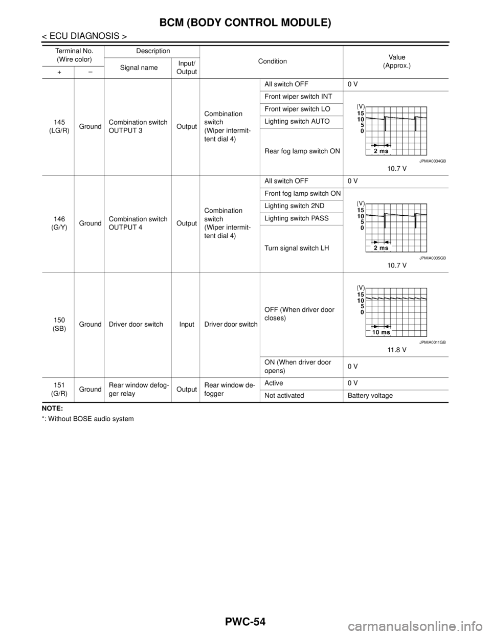
PWC-54
< ECU DIAGNOSIS >
BCM (BODY CONTROL MODULE)
NOTE:
*: Without BOSE audio system145
(LG/R)GroundCombination switch
OUTPUT 3OutputCombination
switch
(Wiper intermit-
tent dial 4)All switch OFF 0 V
Front wiper switch INT
10.7 V Front wiper switch LO
Lighting switch AUTO
Rear fog lamp switch ON
146
(G/Y)GroundCombination switch
OUTPUT 4OutputCombination
switch
(Wiper intermit-
tent dial 4)All switch OFF 0 V
Front fog lamp switch ON
10.7 V Lighting switch 2ND
Lighting switch PASS
Turn signal switch LH
150
(SB)Ground Driver door switch Input Driver door switchOFF (When driver door
closes)
11 . 8 V
ON (When driver door
opens)0 V
151
(G/R)GroundRear window defog-
ger relayOutputRear window de-
foggerActive 0 V
Not activated Battery voltage Te r m i n a l N o .
(Wire color)Description
ConditionVa l u e
(Approx.)
Signal nameInput/
Output +–
JPMIA0034GB
JPMIA0035GB
JPMIA0011GB
Page 3773 of 5121
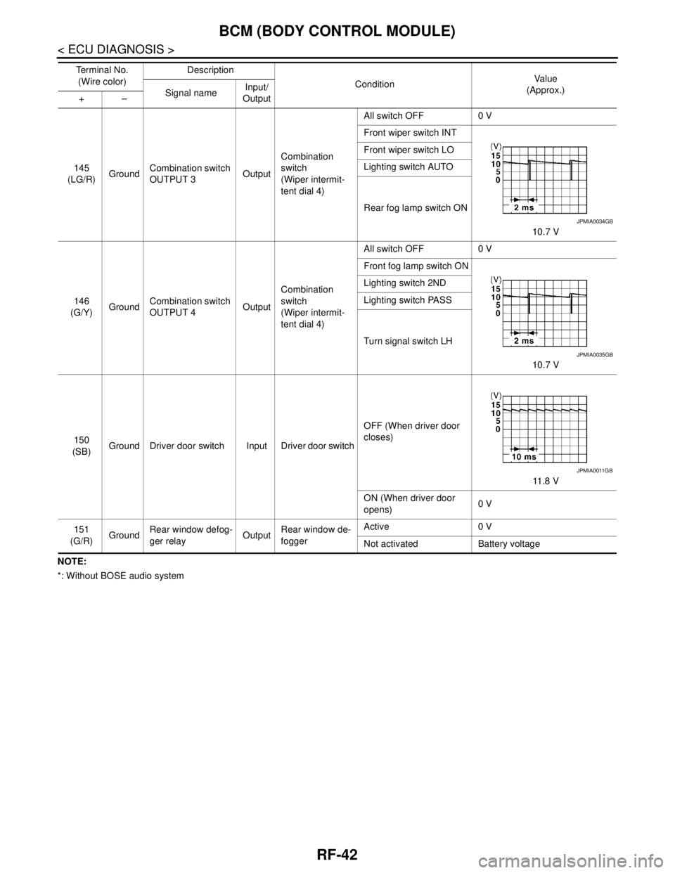
RF-42
< ECU DIAGNOSIS >
BCM (BODY CONTROL MODULE)
NOTE:
*: Without BOSE audio system145
(LG/R)GroundCombination switch
OUTPUT 3OutputCombination
switch
(Wiper intermit-
tent dial 4)All switch OFF 0 V
Front wiper switch INT
10.7 V Front wiper switch LO
Lighting switch AUTO
Rear fog lamp switch ON
146
(G/Y)GroundCombination switch
OUTPUT 4OutputCombination
switch
(Wiper intermit-
tent dial 4)All switch OFF 0 V
Front fog lamp switch ON
10.7 V Lighting switch 2ND
Lighting switch PASS
Turn signal switch LH
150
(SB)Ground Driver door switch Input Driver door switchOFF (When driver door
closes)
11 . 8 V
ON (When driver door
opens)0 V
151
(G/R)GroundRear window defog-
ger relayOutputRear window de-
foggerActive 0 V
Not activated Battery voltage Te r m i n a l N o .
(Wire color)Description
ConditionVa l u e
(Approx.)
Signal nameInput/
Output +–
JPMIA0034GB
JPMIA0035GB
JPMIA0011GB
Page 4175 of 5121
![NISSAN TEANA 2008 Service Manual SEC-166
< ECU DIAGNOSIS >[INTELLIGENT KEY SYSTEM]
BCM (BODY CONTROL MODULE)
NOTE:
*: Without BOSE audio system145
(LG/R)GroundCombination switch
OUTPUT 3OutputCombination
switch
(Wiper intermit-
ten](/img/5/57391/w960_57391-4174.png "NISSAN TEANA 2008 Service Manual SEC-166
< ECU DIAGNOSIS >[INTELLIGENT KEY SYSTEM]
BCM (BODY CONTROL MODULE)
NOTE:
*: Without BOSE audio system145
(LG/R)GroundCombination switch
OUTPUT 3OutputCombination
switch
(Wiper intermit-
ten")
SEC-166
< ECU DIAGNOSIS >[INTELLIGENT KEY SYSTEM]
BCM (BODY CONTROL MODULE)
NOTE:
*: Without BOSE audio system145
(LG/R)GroundCombination switch
OUTPUT 3OutputCombination
switch
(Wiper intermit-
tent dial 4)All switch OFF 0 V
Front wiper switch INT
10.7 V Front wiper switch LO
Lighting switch AUTO
Rear fog lamp switch ON
146
(G/Y)GroundCombination switch
OUTPUT 4OutputCombination
switch
(Wiper intermit-
tent dial 4)All switch OFF 0 V
Front fog lamp switch ON
10.7 V Lighting switch 2ND
Lighting switch PASS
Turn signal switch LH
150
(SB)Ground Driver door switch Input Driver door switchOFF (When driver door
closes)
11 . 8 V
ON (When driver door
opens)0 V
151
(G/R)GroundRear window defog-
ger relayOutputRear window de-
foggerActive 0 V
Not activated Battery voltage Te r m i n a l N o .
(Wire color)Description
ConditionVa l u e
(Approx.)
Signal nameInput/
Output +–
JPMIA0034GB
JPMIA0035GB
JPMIA0011GB