brakes NISSAN TEANA 2008 Service Manual
[x] Cancel search | Manufacturer: NISSAN, Model Year: 2008, Model line: TEANA, Model: NISSAN TEANA 2008Pages: 5121, PDF Size: 69.03 MB
Page 1 of 5121
MODEL J32 SERIES
© 2008 NISSAN INTERNATIONAL SA
Allrightsreserved.NopartofthisElectronicServiceManualmaybereproducedorstoredinaretrievalsystem,ortransmittedinanyform,or by any means, electronic, mechanical, photocopying, recording or otherwise, without the prior written permission of Nissan InternationalSA, Switzerland.
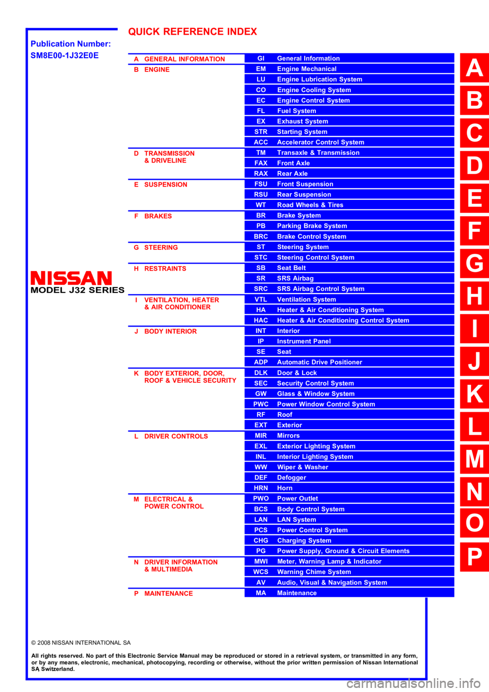
AGENERALINFORMATION
BENGINE
DTRANSMISSION&DRIVELINE
ESUSPENSION
FBRAKES
GSTEERING
HRESTRAINTS
IVENTILATION,HEATER&AIRCONDITIONER
JBODYINTERIOR
KBODYEXTERIOR,DOOR,ROOF&VEHICLESECURITY
LDRIVERCONTROLS
MELECTRICAL&POWERCONTROL
NDRIVERINFORMATION&MULTIMEDIA
PMAINTENANCE
GIGeneralInformation
EMEngineMechanical
LUEngineLubricationSystem
COEngineCoolingSystem
ECEngineControlSystem
FLFuelSystem
EXExhaustSystem
STRStartingSystem
ACCAcceleratorControlSystem
TMTransaxle &Transmission
FAXFrontAxle
RAXRearAxle
FSUFrontSuspension
RSURearSuspension
WTRoadWheels &Tires
BRBrakeSystem
PBParkingBrakeSystem
BRCBrakeControlSystem
STSteeringSystem
STCSteeringControlSystem
SBSeatBelt
SRSRSAirbag
SRCSRSAirbagControlSystem
VTLVentilationSystem
HAHeater &AirConditioningSystem
HACHeater &AirConditioningControlSystem
INTInterior
IPInstrumentPanel
SESeat
ADPAutomaticDrivePositioner
DLKDoor &Lock
SECSecurityControlSystem
GWGlass &WindowSystem
PWCPowerWindowControlSystem
RFRoof
EXTExterior
MIRMirrors
EXLExteriorLightingSystem
INLInteriorLightingSystem
WWWiper &Washer
DEFDefogger
HRNHorn
PWOPowerOutlet
BCSBodyControlSystem
LANLANSystem
PCSPowerControlSystem
CHGChargingSystem
PGPowerSupply,Ground&CircuitElements
MWIMeter,WarningLamp&Indicator
WCSWarningChimeSystem
AVAudio,Visual&NavigationSystem
MAMaintenance
QUICKREFERENCEINDEX
A
B
C
D
E
F
G
H
I
J
K
L
M
N
O
P
M
Publication Number:
SM8E00-1J32E0E
Page 897 of 5121

BR-1
BRAKES
C
DE
G H
I
J
K L
M
SECTION BR
A
B
BR
N
O P
CONTENTS
BRAKE SYSTEM
SYMPTOM DIAGNOSIS ..... ..........................3
NOISE, VIBRATION AND HARSHNESS
(NVH) TROUBLESHOOTING ........................ .....
3
NVH Troubleshooting Chart ................................ ......3
PRECAUTION ...............................................4
PRECAUTIONS .............................................. .....4
Precaution for Supplemental Restraint System
(SRS) "AIR BAG" and "SEAT BELT PRE-TEN-
SIONER" ............................................................. ......
4
Precaution Necessary for Steering Wheel Rota-
tion after Battery Disconnect .....................................
4
Precaution for Procedure without Cowl Top Cover ......5
Precaution for Brake System ....................................5
ON-VEHICLE MAINTENANCE .....................6
BRAKE PEDAL .............................................. .....6
Inspection and Adjustment .................................. ......6
BRAKE FLUID .....................................................9
Inspection ............................................................ ......9
Draining .....................................................................9
Refilling .....................................................................9
Bleeding Brake System ...........................................10
BRAKE MASTER CYLINDER ........................ ....11
Inspection ............................................................ ....11
BRAKE BOOSTER ............................................12
Inspection ............................................................ ....12
FRONT DISC BRAKE .................................... ....13
BRAKE PAD .......................................................... ....13
BRAKE PAD : Inspection and Adjustment ..............13
DISC ROTOR ......................................................... ....13
DISC ROTOR : Inspection and Adjustment ............13
REAR DISC BRAKE ...................................... ....15
BRAKE PAD .......................................................... ....15
BRAKE PAD : Inspection and Adjustment ...............15
DISC ROTOR ......................................................... ....15
DISC ROTOR : Inspection and Adjustment .............15
ON-VEHICLE REPAIR .................................17
BRAKE PEDAL ................................ .................17
Exploded View ..................................................... ....17
Removal and Installation .........................................17
Inspection and Adjustment ......................................18
BRAKE PIPING ................................ .................19
FRONT ................................................................... ....19
FRONT : Exploded View .........................................19
FRONT : Hydraulic Piping .......................................20
FRONT : Removal and Installation ..........................21
FRONT : Inspection .................................................21
REAR ..................................................................... ....22
REAR : Exploded View ............................................22
REAR : Hydraulic Piping ..........................................22
REAR : Removal and Installation ............................23
REAR : Inspection ...................................................23
BRAKE MASTER CYLINDER ..........................25
Exploded View .........................................................25
Removal and Installation .........................................25
Disassembly and Assembly .....................................26
Inspection ................................................................27
BRAKE BOOSTER ...........................................28
Exploded View ..................................................... ....28
Removal and installation .........................................28
Inspection and Adjustment ......................................29
VACUUM LINES ...............................................31
Exploded View .........................................................31
Removal and Installation .........................................31
Inspection ................................................................31
Page 942 of 5121

BRC-1
BRAKES
C
DE
G H
I
J
K L
M
SECTION BRC
A
B
BRC
N
O P
CONTENTS
BRAKE CONTROL SYSTEM
ABS
BASIC INSPECTION ....... .............................
6
DIAGNOSIS AND REPAIR WORK FLOW .... .....6
Work Flow ........................................................... ......6
Diagnostic Work Sheet ..............................................8
FUNCTION DIAGNOSIS ...............................9
ABS ................................................................ .....9
System Diagram .................................................. ......9
System Description ...................................................9
Component Parts Location ......................................10
Component Description ...........................................10
EBD ....................................................................11
System Diagram .................................................. ....11
System Description .................................................11
Component Parts Location ......................................12
Component Description ...........................................12
DIAGNOSIS SYSTEM [ABS ACTUATOR
AND ELECTRIC UNIT (CONTROL UNIT)] ........
13
CONSULT-III Function ........................................ ....13
COMPONENT DIAGNOSIS .........................16
C1101, C1102, C1103, C1104 WHEEL SEN-
SOR ................................................................ ....
16
Description .......................................................... ....16
DTC Logic ...............................................................16
Diagnosis Procedure ...............................................16
Component Inspection ............................................18
C1105, C1106, C1107, C1108 WHEEL SEN-
SOR ....................................................................
19
Description .......................................................... ....19
DTC Logic ...............................................................19
Diagnosis Procedure ...............................................19
Component Inspection ............................................21
C1109 POWER AND GROUND SYSTEM ........22
Description ........................................................... ....22
DTC Logic ................................................................22
Diagnosis Procedure ...............................................22
C1110 ABS ACTUATOR AND ELECTRIC
UNIT (CONTROL UNIT) ....................................
24
DTC Logic ................................................................24
Diagnosis Procedure ...............................................24
C1111 ABS MOTOR, MOTOR RELAY SYS-
TEM ...................................................................
25
Description ...............................................................25
DTC Logic ................................................................25
Diagnosis Procedure ...............................................25
Component Inspection .............................................26
C1115 WHEEL SENSOR ..................................27
Description ...............................................................27
DTC Logic ................................................................27
Diagnosis Procedure ...............................................27
Component Inspection .............................................29
C1116 STOP LAMP SWITCH ...........................30
Description ...............................................................30
DTC Logic ................................................................30
Diagnosis Procedure ...............................................30
Component Inspection .............................................30
C1120, C1122, C1124, C1126 IN ABS SOL .....32
Description ...............................................................32
DTC Logic ................................................................32
Diagnosis Procedure ...............................................32
Component Inspection .............................................33
C1121, C1123, C1125, C1127 OUT ABS SOL ...34
Description ........................................................... ....34
DTC Logic ................................................................34
Diagnosis Procedure ...............................................34
Component Inspection .............................................35
C1140 ACTUATOR RELAY SYSTEM ..............36
Page 1127 of 5121

CO-4
< SYMPTOM DIAGNOSIS >
OVERHEATING CAUSE ANALYSIS
Except cool-
ing system
parts mal-
function— Overload on engineAbusive drivingHigh engine rpm under no
load
Driving in low gear for ex-
tended time
Driving at extremely high
speed
Powertrain system malfunc-
tion
— Installed improper size
wheels and tires
Dragging brakes
Improper ignition timing
Blocked or restricted air
flowBlocked bumper —
— Blocked radiator grilleInstalled car brassiere
Mud contamination or paper
clogging
Blocked radiator —
Blocked condenser
Blocked air flow
Installed large fog lamp Symptom Check items
Page 3221 of 5121
CHASSIS MAINTENANCE
MA-33
< ON-VEHICLE MAINTENANCE >
C
D
E
F
G
H
I
J
K
L
MB
MAN
OA
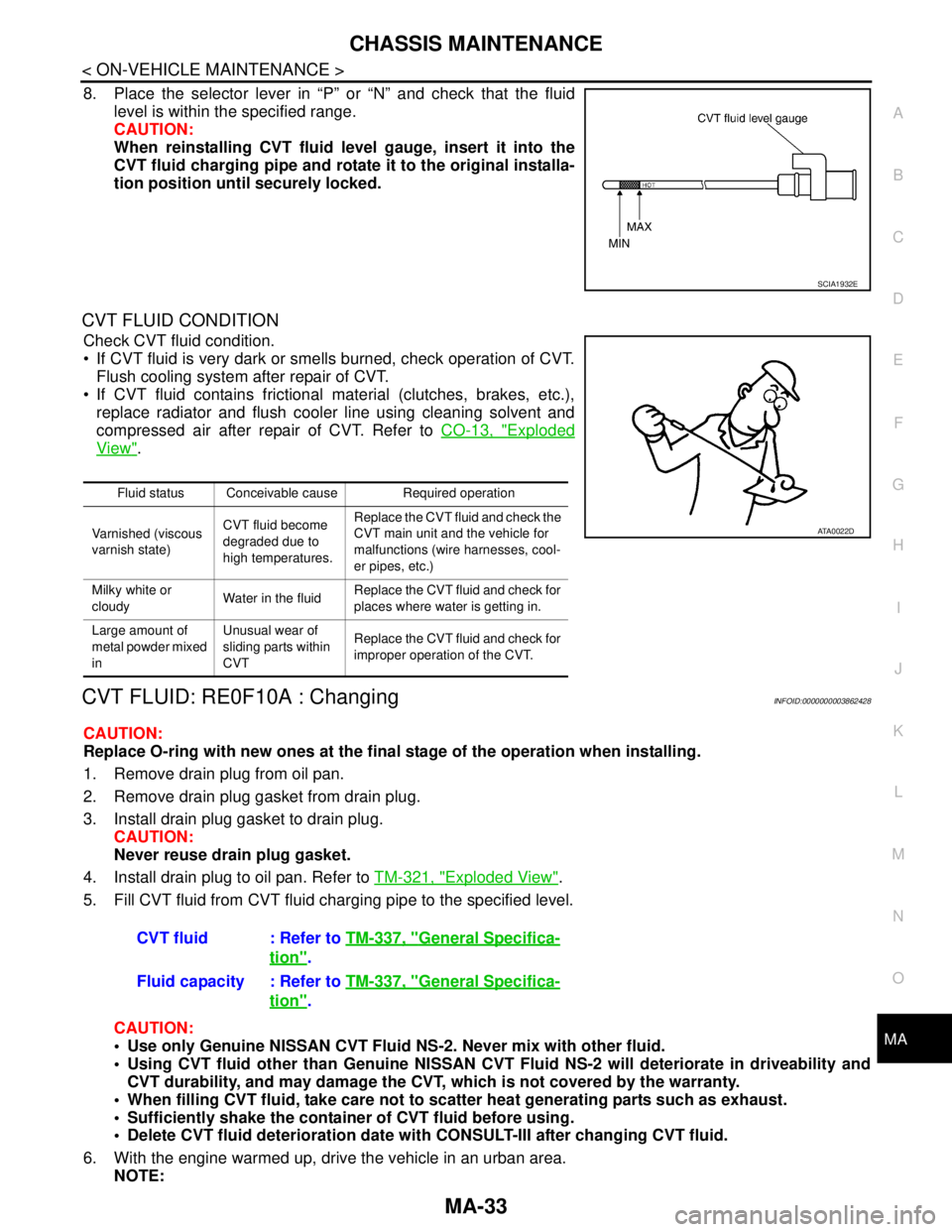
8. Place the selector lever in “P” or “N” and check that the fluid
level is within the specified range.
CAUTION:
When reinstalling CVT fluid level gauge, insert it into the
CVT fluid charging pipe and rotate it to the original installa-
tion position until securely locked.
CVT FLUID CONDITION
Check CVT fluid condition.
If CVT fluid is very dark or smells burned, check operation of CVT.
Flush cooling system after repair of CVT.
If CVT fluid contains frictional material (clutches, brakes, etc.),
replace radiator and flush cooler line using cleaning solvent and
compressed air after repair of CVT. Refer to CO-13, "
Exploded
View".
CVT FLUID: RE0F10A : ChangingINFOID:0000000003862428
CAUTION:
Replace O-ring with new ones at the final stage of the operation when installing.
1. Remove drain plug from oil pan.
2. Remove drain plug gasket from drain plug.
3. Install drain plug gasket to drain plug.
CAUTION:
Never reuse drain plug gasket.
4. Install drain plug to oil pan. Refer to TM-321, "
Exploded View".
5. Fill CVT fluid from CVT fluid charging pipe to the specified level.
CAUTION:
Use only Genuine NISSAN CVT Fluid NS-2. Never mix with other fluid.
Using CVT fluid other than Genuine NISSAN CVT Fluid NS-2 will deteriorate in driveability and
CVT durability, and may damage the CVT, which is not covered by the warranty.
When filling CVT fluid, take care not to scatter heat generating parts such as exhaust.
Sufficiently shake the container of CVT fluid before using.
Delete CVT fluid deterioration date with CONSULT-III after changing CVT fluid.
6. With the engine warmed up, drive the vehicle in an urban area.
NOTE:
SCIA1932E
Fluid status Conceivable cause Required operation
Varnished (viscous
varnish state)CVT fluid become
degraded due to
high temperatures.Replace the CVT fluid and check the
CVT main unit and the vehicle for
malfunctions (wire harnesses, cool-
er pipes, etc.)
Milky white or
cloudyWater in the fluidReplace the CVT fluid and check for
places where water is getting in.
Large amount of
metal powder mixed
inUnusual wear of
sliding parts within
CVTReplace the CVT fluid and check for
improper operation of the CVT.
ATA0022D
CVT fluid : Refer to TM-337, "General Specifica-
tion".
Fluid capacity : Refer to TM-337, "
General Specifica-
tion".
Page 3223 of 5121
CHASSIS MAINTENANCE
MA-35
< ON-VEHICLE MAINTENANCE >
C
D
E
F
G
H
I
J
K
L
MB
MAN
OA
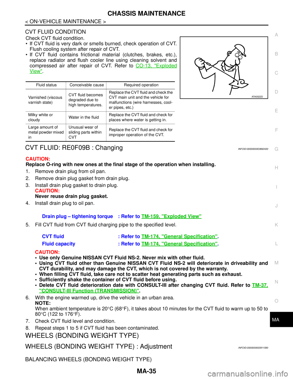
CVT FLUID CONDITION
Check CVT fluid condition.
If CVT fluid is very dark or smells burned, check operation of CVT.
Flush cooling system after repair of CVT.
If CVT fluid contains frictional material (clutches, brakes, etc.),
replace radiator and flush cooler line using cleaning solvent and
compressed air after repair of CVT. Refer to CO-13, "
Exploded
View".
CVT FLUID: RE0F09B : ChangingINFOID:0000000003862430
CAUTION:
Replace O-ring with new ones at the final stage of the operation when installing.
1. Remove drain plug from oil pan.
2. Remove drain plug gasket from drain plug.
3. Install drain plug gasket to drain plug.
CAUTION:
Never reuse drain plug gasket.
4. Install drain plug to oil pan.
5. Fill CVT fluid from CVT fluid charging pipe to the specified level.
CAUTION:
Use only Genuine NISSAN CVT Fluid NS-2. Never mix with other fluid.
Using CVT fluid other than Genuine NISSAN CVT Fluid NS-2 will deteriorate in driveability and
CVT durability, and may damage the CVT, which is not covered by the warranty.
When filling CVT fluid, take care not to scatter heat generating parts such as exhaust.
Sufficiently shake the container of CVT fluid before using.
Delete CVT fluid deterioration date with CONSULT-III after changing CVT fluid. Refer to TM-37,
"CONSULT-III Function (TRANSMISSION)".
6. With the engine warmed up, drive the vehicle in an urban area.
NOTE:
When ambient temperature is 20°C (68°F), it takes about 10 minutes for the CVT fluid to warm up to 50 to
80°C (122 to 176°F).
7. Check CVT fluid level and condition.
8. Repeat steps 1 to 5 if CVT fluid has been contaminated.
WHEELS (BONDING WEIGHT TYPE)
WHEELS (BONDING WEIGHT TYPE) : AdjustmentINFOID:0000000003911590
BALANCING WHEELS (BONDING WEIGHT TYPE)
Fluid status Conceivable cause Required operation
Varnished (viscous
varnish state)CVT fluid becomes
degraded due to
high temperatures.Replace the CVT fluid and check the
CVT main unit and the vehicle for
malfunctions (wire harnesses, cool-
er pipes, etc.)
Milky white or
cloudyWater in the fluidReplace the CVT fluid and check for
places where water is getting in.
Large amount of
metal powder mixed
inUnusual wear of
sliding parts within
CVTReplace the CVT fluid and check for
improper operation of the CVT.
ATA0022D
Drain plug – tightening torque : Refer to TM-159, "Exploded View"
CVT fluid : Refer to TM-174, "General Specification".
Fluid capacity : Refer to TM-174, "
General Specification".
Page 3382 of 5121

PB-1
BRAKES
C
DE
G H
I
J
K L
M
SECTION PB
A
B
PB
N
O P
CONTENTS
PARKING BRAKE SYSTEM
ON-VEHICLE MAINTENA NCE .....................2
PARKING BRAKE SYSTEM .......................... .....2
Inspection and Adjustment .................................. ......2
PARKING BRAKE SHOE ...................................4
Adjustment .......................................................... ......4
ON-VEHICLE REPAIR ..................................5
PARKING BRAKE CONTROL ....................... .....5
Exploded View .................................................... ......5
Removal and Installation ...........................................5
Adjustment ................................................................6
PARKING BRAKE SHOE ..................................7
Exploded View ..................................................... .....7
Removal and Installation ..........................................7
Inspection and Adjustment .......................................8
SERVICE DATA AND SPECIFICATIONS
(SDS) ............... .............................................
10
SERVICE DATA AND SPECIFICATIONS
(SDS) .................................................................
10
Parking Drum Brake ............................................ ....10
Parking Brake Control .............................................10
Page 3856 of 5121
SB-4
< ON-VEHICLE REPAIR >
FRONT SEAT BELT
6. Remove the clip fixing the seat belt and check that the webbing returns smoothly.
6. Repeat steps above as necessary to check the other seat belts.
SEAT BELT RETRACTOR ON-VEHICLE CHECK
Emergency Locking Retractors (ELR) and Automatic Locking Retractors (ALR)
NOTE:
All seat belt retractors are Emergency Locking Retractors (ELR) type. In an emergency (sudden stop) the
retractor will lock and prevent the webbing from extending any further. All 3-point type seat belt retractors
except the driver seat belt also have an Automatic Locking Retractors (ALR) mode. The ALR mode (also
called child restraint mode) is used when installing child seats. The ALR mode is activated when the seat belt
is fully extended. When the webbing is then retracted partially, the ALR mode automatically locks the seat belt
in a specific position so the webbing cannot be extended any further. To cancel the ALR mode, allow the seat
belt to fully wind back into the retractor.
Check the seat belt retractors with the following test(s) to determine if a retractor assembly is operating prop-
erly.
ELR Function Stationary Check
Grasp the shoulder webbing and pull forward quickly. The retractor should lock and prevent the belt from
extending further.
ALR Function Stationary Check
1. Pull out the entire length of seat belt from retractor until a click is heard.
2. Retract the webbing partially. A clicking noise should be heard as the webbing retracts indicating that the
retractor is in the Automatic Locking Retractors (ALR) mode.
3. Grasp the seat belt and try to pull out the retractor. The webbing must lock and not extend any further. If
NG, replace the retractor assembly.
4. Allow the entire length of the webbing to retract to cancel the automatic locking mode.
ELR Function Moving Check
WARNING:
Perform the following test in a safe, open area clear of other vehicles and obstructions (for example, a
large, empty parking lot). Road surface must be paved and dry. Never perform the following test on
wet or gravel roads or on public streets and highways. This could result in an accident and serious
personal injury. The driver and passenger must be prepared to brace themselves in the event that the
retractor does not lock.
1. Fasten driver seat belt. Buckle a passenger into the seat for the belt that is to be tested.
2. Proceed to the designated safe area.
3. Drive the vehicle at approximately 16 km/h (10 MPH). Notify any passengers of a pending sudden stop
and the driver and passenger must be prepared to brace themselves in the event that the retractor does
not lock, apply brakes firmly and make a very hard stop.
During stopping, seat belts should lock and not be extended. If the seat belt retractor assembly does not lock,
perform the retractor off-vehicle check.
SEAT BELT RETRACTOR OFF-VEHICLE CHECK
1. Remove the seat belt retractor.
Remove the front seat belt assembly, refer to SB-5, "
SEAT BELT RETRACTOR : Removal and Installa-
tion".
2. Slowly pull out webbing while tilting the retractor assembly forward from the mounted position without
twisting the retractor assembly as shown in the illustration.
Page 3861 of 5121
REAR SEAT BELT
SB-9
< ON-VEHICLE REPAIR >
C
D
E
F
G
I
J
K
L
MA
B
SB
N
O
P
Grasp the shoulder webbing and pull forward quickly. The retractor should lock and prevent the belt from
extending further.
ALR Function Stationary Check
1. Pull out the entire length of seat belt from retractor until a click is heard.
2. Retract the webbing partially. A clicking noise should be heard as the webbing retracts indicating that the
retractor is in the Automatic Locking Retractors (ALR) mode.
3. Grasp the seat belt and try to pull out the retractor. The webbing must lock and not extend any further. If
NG, replace the retractor assembly.
4. Allow the entire length of the webbing to retract to cancel the automatic locking mode.
ELR Function Moving Check
WARNING:
Perform the following test in a safe, open area clear of other vehicles and obstructions (for example, a
large, empty parking lot). Road surface must be paved and dry. NEVER perform the following test on
wet or gravel roads or on public streets and highways. This could result in an accident and serious
personal injury. The driver and passenger must be prepared to brace themselves in the event that the
retractor does not lock.
1. Fasten driver seat belt. Buckle a passenger into the seat for the belt that is to be tested.
2. Proceed to the designated safe area.
3. Drive the vehicle at approximately 16 km/h (10 MPH). Notify any passengers of a pending sudden stop
and the driver and passenger must be prepared to brace themselves in the event that the retractor does
not lock, apply brakes firmly and make a very hard stop.
During stopping, seat belts should lock and not be extended. If the seat belt retractor assembly does not lock,
perform the retractor off-vehicle check.
SEAT BELT RETRACTOR OFF-VEHICLE CHECK
1. Remove the seat belt retractor.
Remove the rear seat belt assembly, refer to SB-10, "
SEAT BELT RETRACTOR : Removal and Installa-
tion".
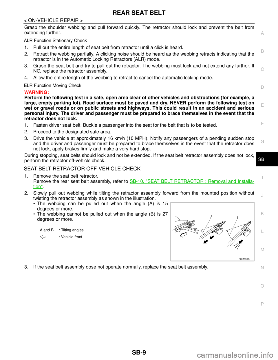
2. Slowly pull out webbing while tilting the retractor assembly forward from the mounted position without
twisting the retractor assembly as shown in the illustration.
The webbing can be pulled out when the angle (A) is 15
degrees or more.
The webbing cannot be pulled out when the angle (B) is 27
degrees or more.
3. If the seat belt assembly dose not operate normally, replace the seat belt assembly.
A and B : Tilting angles
: Vehicle front
PHIA0962J
Page 4616 of 5121
![NISSAN TEANA 2008 Service Manual CVT FLUID
TM-143
< ON-VEHICLE MAINTENANCE >[CVT: RE0F09B]
C
E
F
G
H
I
J
K
L
MA
B
TM
N
O
P
Check CVT fluid condition.
If CVT fluid is very dark or smells burned, check operation of CVT.
Flush cooling NISSAN TEANA 2008 Service Manual CVT FLUID
TM-143
< ON-VEHICLE MAINTENANCE >[CVT: RE0F09B]
C
E
F
G
H
I
J
K
L
MA
B
TM
N
O
P
Check CVT fluid condition.
If CVT fluid is very dark or smells burned, check operation of CVT.
Flush cooling](/img/5/57391/w960_57391-4615.png)
CVT FLUID
TM-143
< ON-VEHICLE MAINTENANCE >[CVT: RE0F09B]
C
E
F
G
H
I
J
K
L
MA
B
TM
N
O
P
Check CVT fluid condition.
If CVT fluid is very dark or smells burned, check operation of CVT.
Flush cooling system after repair of CVT.
If CVT fluid contains frictional material (clutches, brakes, etc.),
replace radiator and flush cooler line using cleaning solvent and
compressed air after repair of CVT. Refer to CO-13, "
Exploded
View".
ChangingINFOID:0000000003849077
CAUTION:
Replace O-ring with new ones at the final stage of the operation when installing.
1. Remove drain plug from oil pan.
2. Remove drain plug gasket from drain plug.
3. Install drain plug gasket to drain plug.
CAUTION:
Never reuse drain plug gasket.
4. Install drain plug to oil pan.
5. Fill CVT fluid from CVT fluid charging pipe to the specified level.
CAUTION:
Use only Genuine NISSAN CVT Fluid NS-2. Never mix with other fluid.
Using CVT fluid other than Genuine NISSAN CVT Fluid NS-2 will deteriorate in driveability and
CVT durability, and may damage the CVT, which is not covered by the warranty.
When filling CVT fluid, take care not to scatter heat generating parts such as exhaust.
Sufficiently shake the container of CVT fluid before using.
Delete CVT fluid deterioration date with CONSULT-III after changing CVT fluid. Refer to TM-37,
"CONSULT-III Function (TRANSMISSION)".
6. With the engine warmed up, drive the vehicle in an urban area.
NOTE:
When ambient temperature is 20°C (68°F), it takes about 10 minutes for the CVT fluid to warm up to 50 to
80°C (122 to 176°F).
7. Check CVT fluid level and condition.
8. Repeat steps 1 to 5 if CVT fluid has been contaminated.
Fluid status Conceivable cause Required operation
Varnished (viscous
varnish state)CVT fluid becomes
degraded due to
high temperatures.Replace the CVT fluid and check the
CVT main unit and the vehicle for
malfunctions (wire harnesses, cool-
er pipes, etc.)
Milky white or
cloudyWater in the fluidReplace the CVT fluid and check for
places where water is getting in.
Large amount of
metal powder mixed
inUnusual wear of
sliding parts within
CVTReplace the CVT fluid and check for
improper operation of the CVT.
ATA0022D
Drain plug – tightening torque : Refer to TM-159, "Exploded View"
CVT fluid : Refer to TM-174, "General Specification".
Fluid capacity : Refer to TM-174, "
General Specification".