airbag off NISSAN TEANA 2008 User Guide
[x] Cancel search | Manufacturer: NISSAN, Model Year: 2008, Model line: TEANA, Model: NISSAN TEANA 2008Pages: 5121, PDF Size: 69.03 MB
Page 3087 of 5121
![NISSAN TEANA 2008 User Guide LAN-20
< PRECAUTION >[CAN]
PRECAUTIONS
PRECAUTION
PRECAUTIONS
Precaution for Supplemental Restraint System (SRS) "AIR BAG" and "SEAT BELT
PRE-TENSIONER"
INFOID:0000000003850219
The Supplemental Restr NISSAN TEANA 2008 User Guide LAN-20
< PRECAUTION >[CAN]
PRECAUTIONS
PRECAUTION
PRECAUTIONS
Precaution for Supplemental Restraint System (SRS) "AIR BAG" and "SEAT BELT
PRE-TENSIONER"
INFOID:0000000003850219
The Supplemental Restr](/img/5/57391/w960_57391-3086.png)
LAN-20
< PRECAUTION >[CAN]
PRECAUTIONS
PRECAUTION
PRECAUTIONS
Precaution for Supplemental Restraint System (SRS) "AIR BAG" and "SEAT BELT
PRE-TENSIONER"
INFOID:0000000003850219
The Supplemental Restraint System such as “AIR BAG” and “SEAT BELT PRE-TENSIONER”, used along
with a front seat belt, helps to reduce the risk or severity of injury to the driver and front passenger for certain
types of collision. Information necessary to service the system safely is included in the “SRS AIRBAG” and
“SEAT BELT” of this Service Manual.
WARNING:
To avoid rendering the SRS inoperative, which could increase the risk of personal injury or death in
the event of a collision which would result in air bag inflation, all maintenance must be performed by
an authorized NISSAN/INFINITI dealer.
Improper maintenance, including incorrect removal and installation of the SRS, can lead to personal
injury caused by unintentional activation of the system. For removal of Spiral Cable and Air Bag
Module, see the “SRS AIRBAG”.
Never use electrical test equipment on any circuit related to the SRS unless instructed to in this Ser-
vice Manual. SRS wiring harnesses can be identified by yellow and/or orange harnesses or harness
connectors.
Precautions for Trouble DiagnosisINFOID:0000000003767681
CAUTION:
Never apply 7.0 V or more to the measurement terminal.
Use a tester with open terminal voltage of 7.0 V or less.
Turn the ignition switch OFF and disconnect the battery cable from the negative terminal when
checking the harness.
Precautions for Harness RepairINFOID:0000000003767682
Solder the repaired area and wrap tape around the soldered area.
NOTE:
A fray of twisted lines must be within 110 mm (4.33 in).
Bypass connection is never allowed at the repaired area.
NOTE:
Bypass connection may cause CAN communication error. The
spliced wire becomes separated and the characteristics of twisted
line are lost.
Replace the applicable harness as an assembly if error is detected on the shield lines of CAN communica-
tion line.
SKIB8766E
SKIB8767E
Page 3808 of 5121
PRECAUTIONS
RF-77
< PRECAUTION >
C
D
E
F
G
H
I
J
L
MA
B
RF
N
O
P
PRECAUTION
PRECAUTIONS
Precaution for Supplemental Restraint System (SRS) "AIR BAG" and "SEAT BELT
PRE-TENSIONER"
INFOID:0000000003940151
The Supplemental Restraint System such as “AIR BAG” and “SEAT BELT PRE-TENSIONER”, used along
with a front seat belt, helps to reduce the risk or severity of injury to the driver and front passenger for certain
types of collision. Information necessary to service the system safely is included in the “SRS AIRBAG” and
“SEAT BELT” of this Service Manual.
WARNING:
To avoid rendering the SRS inoperative, which could increase the risk of personal injury or death in
the event of a collision which would result in air bag inflation, all maintenance must be performed by
an authorized NISSAN/INFINITI dealer.
Improper maintenance, including incorrect removal and installation of the SRS, can lead to personal
injury caused by unintentional activation of the system. For removal of Spiral Cable and Air Bag
Module, see the “SRS AIRBAG”.
Never use electrical test equipment on any circuit related to the SRS unless instructed to in this Ser-
vice Manual. SRS wiring harnesses can be identified by yellow and/or orange harnesses or harness
connectors.
Service NoticeINFOID:0000000003812880
When removing or installing various parts, place a cloth or padding onto the vehicle body to prevent
scratches.
Handle trim, molding, instruments, grille, etc. carefully during removing or installing. Be careful not to oil or
damage them.
Apply sealing compound where necessary when installing parts.
When applying sealing compound, be careful that the sealing compound does not protrude from parts.
When replacing any metal parts (for example body outer panel, members, etc.), be sure to take rust preven-
tion measures.
Precaution for WorkINFOID:0000000003812881
When removing or disassembling each component, be careful not to damage or deform it. If a component
may be subject to interference, be sure to protect it with a shop cloth.
When removing (disengaging) components with a screwdriver or similar tool, be sure to wrap the component
with a shop cloth or vinyl tape to protect it.
Protect the removed parts with a shop cloth and keep them.
Replace a deformed or damaged clip.
If a part is specified as a non-reusable part, always replace it with new one.
Be sure to tighten bolts and nuts securely to the specified torque.
After re-installation is completed, be sure to check that each part works normally.
Follow the steps below to clean components.
- Water soluble foul: Dip a soft cloth into lukewarm water, and wring the water out of the cloth to wipe the
fouled area.
Then rub with a soft and dry cloth.
- Oily foul: Dip a soft cloth into lukewarm water with mild detergent (concentration: within 2 to 3%), and wipe
the fouled area.
Then dip a cloth into fresh water, and wring the water out of the cloth to wipe the detergent off. Then rub with
a soft and dry cloth.
Do not use organic solvent such as thinner, benzene, alcohol, and gasoline.
For genuine leather seats, use a genuine leather seat cleaner.
Page 3854 of 5121
SB-2
< PRECAUTION >
PRECAUTIONS
PRECAUTION
PRECAUTIONS
Precaution for Supplemental Restraint System (SRS) "AIR BAG" and "SEAT BELT
PRE-TENSIONER"
INFOID:0000000003949049
The Supplemental Restraint System such as “AIR BAG” and “SEAT BELT PRE-TENSIONER”, used along
with a front seat belt, helps to reduce the risk or severity of injury to the driver and front passenger for certain
types of collision. Information necessary to service the system safely is included in the “SRS AIRBAG” and
“SEAT BELT” of this Service Manual.
WARNING:
• To avoid rendering the SRS inoperative, which could increase the risk of personal injury or death in
the event of a collision which would result in air bag inflation, all maintenance must be performed by
an authorized NISSAN/INFINITI dealer.
Improper maintenance, including incorrect removal and installation of the SRS, can lead to personal
injury caused by unintentional activation of the system. For removal of Spiral Cable and Air Bag
Module, see the “SRS AIRBAG”.
Never use electrical test equipment on any circuit related to the SRS unless instructed to in this Ser-
vice Manual. SRS wiring harnesses can be identified by yellow and/or orange harnesses or harness
connectors.
Precaution for Seat Belt ServiceINFOID:0000000003848851
CAUTION:
Before removing the front seat belt pre-tensioner assembly, turn the ignition switch OFF, disconnect
both battery cables and wait at least 3 minutes.
Never use electrical test equipment for front seat belt pre-tensioner connector.
After replacing or reinstalling front seat belt pre-tensioner assembly, or reconnecting front seat belt
pre-tensioner connector, check the system function. Refer to SRC-10, "
Diagnosis Description".
Deploy front seat belt pre-tensioner assembly before disposing. Refer to SR-25, "
Caution for Air Bag
Module and Seat Belt Pre-tensioner"
Never use disassembled buckle or seat belt assembly.
Replace anchor bolts if they are deformed or worn out.
Never oil tongue and buckle.
If any component of seat belt assembly is questionable, never repair. Replace the entire seat belt
assembly.
If webbing is cut, frayed or damaged, replace seat belt assembly.
When replacing seat belt assembly, use a Genuine NISSAN seat belt assembly.
AFTER A COLLISION
WARNING:
Inspect all seat belt assemblies including retractors and attached hardware after any collision.
NISSAN recommends that all seat belt assemblies in use during a collision be replaced unless the col-
lision was minor and the belts show no damage and continue to operate properly. Not doing so could
result in serious personal injury in an accident. Seat belt assemblies not in use during a collision
should also be replaced if either damage or improper operation is noted. Seat belt pre-tensioners
should be replaced even if the seat belts are not in use during a frontal collision in which the air bags
are deployed.
Replace any seat belt assembly (including anchor bolts) if:
The seat belt is in use at the time of a collision (except for minor collisions and the belts, retractors and buck-
les show no damage and continue to operate properly).
The seat belt is damaged in an accident (i.e. torn webbing, bent retractor or guide).
The seat belt attaching point is damaged in an accident. Inspect the seat belt attaching area for damage or
distortion and repair as necessary before installing a new seat belt assembly.
Anchor bolts are deformed or worn out.
The front seat belt pre-tensioner must be replaced even if the seat belts are not in use during the collision in
which the air bags are deployed.
Page 4216 of 5121

SR-2
< PRECAUTION >
PRECAUTIONS
PRECAUTION
PRECAUTIONS
Precaution for Supplemental Restraint System (SRS) "AIR BAG" and "SEAT BELT
PRE-TENSIONER"
INFOID:0000000003838497
The Supplemental Restraint System such as “AIR BAG” and “SEAT BELT PRE-TENSIONER”, used along
with a front seat belt, helps to reduce the risk or severity of injury to the driver and front passenger for certain
types of collision. Information necessary to service the system safely is included in the “SRS AIRBAG” and
“SEAT BELT” of this Service Manual.
WARNING:
• To avoid rendering the SRS inoperative, which could increase the risk of personal injury or death in
the event of a collision which would result in air bag inflation, all maintenance must be performed by
an authorized NISSAN/INFINITI dealer.
Improper maintenance, including incorrect removal and installation of the SRS, can lead to personal
injury caused by unintentional activation of the system. For removal of Spiral Cable and Air Bag
Module, see the “SRS AIRBAG”.
Never use electrical test equipment on any circuit related to the SRS unless instructed to in this Ser-
vice Manual. SRS wiring harnesses can be identified by yellow and/or orange harnesses or harness
connectors.
Precaution Necessary for Steering Wheel Rotation after Battery Disconnect
INFOID:0000000003838498
NOTE:
Before removing and installing any control units, first turn the push-button ignition switch to the LOCK posi-
tion, then disconnect both battery cables.
After finishing work, confirm that all control unit connectors are connected properly, then re-connect both
battery cables.
Always use CONSULT-III to perform self-diagnosis as a part of each function inspection after finishing work.
If a DTC is detected, perform trouble diagnosis according to self-diagnosis results.
This vehicle is equipped with a push-button ignition switch and a steering lock unit.
If the battery is disconnected or discharged, the steering wheel will lock and cannot be turned.
If turning the steering wheel is required with the battery disconnected or discharged, follow the procedure
below before starting the repair operation.
OPERATION PROCEDURE
1. Connect both battery cables.
NOTE:
Supply power using jumper cables if battery is discharged.
2. Turn the push-button ignition switch to ACC position.
(At this time, the steering lock will be released.)
3. Disconnect both battery cables. The steering lock will remain released with both battery cables discon-
nected and the steering wheel can be turned.
4. Perform the necessary repair operation.
5. When the repair work is completed, re-connect both battery cables. With the brake pedal released, turn
the push-button ignition switch from ACC position to ON position, then to LOCK position. (The steering
wheel will lock when the push-button ignition switch is turned to LOCK position.)
6. Perform self-diagnosis check of all control units using CONSULT-III.
ServiceINFOID:0000000003751420
Do not use electrical test equipment to check SRS circuits unless instructed to in this Service Manual.
Before servicing the SRS, turn ignition switch OFF, disconnect both battery cables and wait at least 3 min-
utes.
For approximately 3 minutes after the cables are removed, it is still possible for the air bag and seat belt pre-
tensioner to deploy. Therefore, do not work on any SRS connectors or wires until at least 3 minutes have
elapsed.
Page 4253 of 5121
SRC-10
< FUNCTION DIAGNOSIS >
DIAGNOSIS SYSTEM (AIRBAG)
DIAGNOSIS SYSTEM (AIRBAG)
Diagnosis DescriptionINFOID:0000000003813934
CAUTION:
• Never use electrical test equipment on any circuit related to the SRS unless instructed in this Ser-
vice Manual. SRS wiring harnesses can be identified by yellow and/or orange harnesses or harness
connectors.
Never repair, splice or modify the SRS wiring harness. If the harness is damaged, replace it with a
new one.
Keep ground portion clean.
DIAGNOSIS FUNCTION
The SRS self-diagnosis results can be read by using air bag warning lamp and/or CONSULT-III.
The user mode is exclusively prepared for the customer (driver). This mode warns the driver of a system
malfunction through the operation of the air bag warning lamp.
The diagnosis mode allows the technician to locate and inspect the malfunctioning part.
The mode applications for the air bag warning lamp and CONSULT-III are as follows.
HOW TO PERFORM TROUBLE DIAGNOSIS FOR QUICK AND ACCURATE REPAIR
A good understanding of the malfunction conditions can make troubleshooting faster and more accurate.
In general, each customer feels differently about a malfunction. It is important to fully understand the symp-
toms or conditions for a customer complaint.
Information from Customer.
WHAT..... Vehicle model.
WHEN..... Date, Frequency.
WHERE..... Road conditions.
HOW..... Operating conditions, Symptoms.
Preliminary Check.
Check that the following parts are in good order.
Battery (Refer to PG-3, "
How to Handle Battery").
Fuse (Refer to PG-82, "
Fuse").
System component-to-harness connections.
Air Bag Warning Lamp DiagnosisINFOID:0000000003843289
SELF-DIAGNOSIS FUNCTION
The reading of these results is accomplished by “User mode” and “Diagnosis mode”.
After a malfunction is repaired, turn ignition switch ON. Diagnosis mode returns to the User mode. At that
time, the self-diagnosis result is cleared.
User mode Diagnosis mode Display type
Air bag warning lamp X X ON-OFF operation
CONSULT-III – X Monitoring
Page 4254 of 5121
DIAGNOSIS SYSTEM (AIRBAG)
SRC-11
< FUNCTION DIAGNOSIS >
C
D
E
F
G
I
J
K
L
MA
B
SRC
N
O
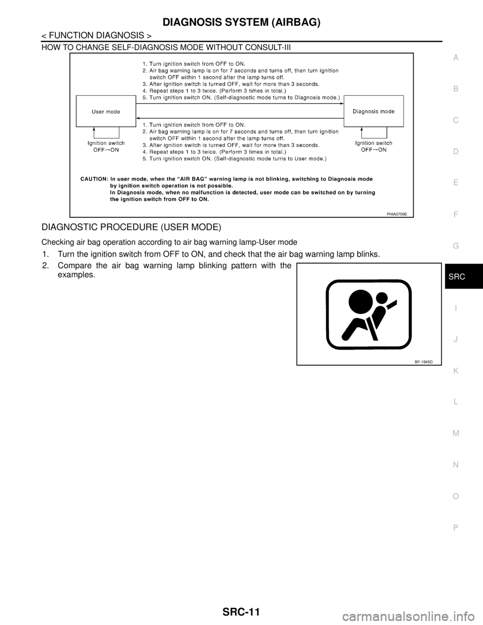
P HOW TO CHANGE SELF-DIAGNOSIS MODE WITHOUT CONSULT-III
DIAGNOSTIC PROCEDURE (USER MODE)
Checking air bag operation according to air bag warning lamp-User mode
1. Turn the ignition switch from OFF to ON, and check that the air bag warning lamp blinks.
2. Compare the air bag warning lamp blinking pattern with the
examples.
PHIA0709E
BF-1845D
Page 4258 of 5121
DIAGNOSIS SYSTEM (AIRBAG)
SRC-15
< FUNCTION DIAGNOSIS >
C
D
E
F
G
I
J
K
L
MA
B
SRC
N
O
P
After a malfunction is repaired, turn the ignition switch OFF for at least one second, then turn ignition switch
ON. Diagnosis mode returns to the user mode. At that time the self-diagnosis result is cleared.
CONSULT-III FunctionINFOID:0000000003813935
HOW TO CHANGE SELF-DIAGNOSIS MODE WITH CONSULT-III
From User Mode to Diagnosis Mode
After selecting “AIR BAG” on the “SELECT SYSTEM” screen, User mode automatically changes to Diagnosis
mode.
From Diagnosis Mode to User Mode
To return to User mode from Diagnosis mode, touch “BACK” key of CONSULT-III until “SELECT SYSTEM”
appears, then Diagnosis mode automatically changes to User mode.
DIAGNOSIS MODE FOR CONSULT-III
“SELF-DIAG [CURRENT]”
Current self-diagnosis results (also indicated with the number of air bag warning lamp blinks in Diagnosis
mode) are displayed on CONSULT-III screen in real time. This refers to a malfunctioning part requiring
repairs.
“SELF-DIAG [PAST]”
Diagnosis results previously stored in the memory are displayed on CONSULT-III screen. The stored results
are not erased until memory erasing is executed.
“TROUBLE DIAG RECORD”
With TROUBLE DIAG RECORD, diagnosis results previously erased by a reset operation can be displayed
on CONSULT-III screen.
“DISCRIMINATED NO.”
The air bag diagnosis sensor unit for each vehicle model has its own individual classification number. This
number is displayed on CONSULT-III screen. When replacing the air bag diagnosis sensor unit, refer to the
part number for the compatibility. After installation, replacement with a correct unit can be checked by con-
firming this classification number on CONSULT-III screen.
After repair, check that the discriminated number of air bag diagnosis sensor unit installed to vehicle is the
same. Refer to SR-22, "
Exploded View".
HOW TO ERASE SELF-DIAGNOSTIC RESULTS
“SELF-DIAG [CURRENT]”
A current self-diagnosis result is displayed on CONSULT-III screen in real time.
After the malfunction is repaired completely, no malfunction is detected on “SELF-DIAG [CURRENT]”.
“SELF-DIAG [PAST]”
Return to “SELF-DIAG [CURRENT]” CONSULT-III screen by touching “BACK” key of CONSULT-III and
select “SELF-DIAG [CURRENT]” in SELECT DIAG MODE. Touch “ERASE” in “SELF-DIAG [CURRENT]”
mode.
NOTE:
If the memory of the malfunction in “SELF-DIAG [PAST]” is not erased, the user mode shows the system
malfunction by illuminating the warning lamp even if the malfunction is repaired completely.
“TROUBLE DIAG RECORD”
The memory of “TROUBLE DIAG RECORD” cannot be erased.
Page 4275 of 5121
SRC-32
< COMPONENT DIAGNOSIS >
B1049 DRIVER AIRBAG MODULE
B1049 DRIVER AIRBAG MODULE
DescriptionINFOID:0000000003813957
For driver air bag module, crash is judged by main “G” sensor output signal and safing algorithm in front direc-
tion.
OPERATION
In case of frontal collision whose acceleration exceeds the specified level, the ignition materials are ignited by
electric ignition system. The system burns the gas generating materials resulting in a chemical reaction. This
generates hot gases that flow into the air bag through a filter and expand the bag.
STRUCTURE
Driver air bag module mainly consists of air bag and inflator which inflates air bag.
INSTALLATION
Driver air bag module is installed on the center of steering wheel with fixed bolts.
DTC LogicINFOID:0000000003813958
DTC CONFIRMATION PROCEDURE
1.CHECK SELF-DIAG RESULT
With CONSULT-III
1. Turn ignition switch ON.
2. Perform “AIR BAG” Self Diagnostic Result.
Without CONSULT-III
1. Turn ignition switch ON.
2. Check the air bag warning lamp status. Refer to SRC-10, "
Air Bag Warning Lamp Diagnosis".
NOTE:
SRS does not enter Diagnosis mode if no malfunction is detected in User mode.
Is malfunctioning part detected?
YES >> Refer to SRC-32, "Diagnosis Procedure".
NO >> INSPECTION END
Diagnosis ProcedureINFOID:0000000003813959
WARNING:
With CONSULT-III
Before servicing, turn ignition switch OFF, disconnect battery negative terminal and wait at least 3
minutes. (To discharge backup capacitor.)
Never use unspecified tester or other measuring device.
1.CHECK HARNESS CONNECTOR
Check the harness connector.
Is the inspection result normal?
YES >> GO TO 2.
NO >> Replace harness connector.
2.CHECK WIRING HARNESS
Check the wiring harness externals.
Is the inspection result normal?
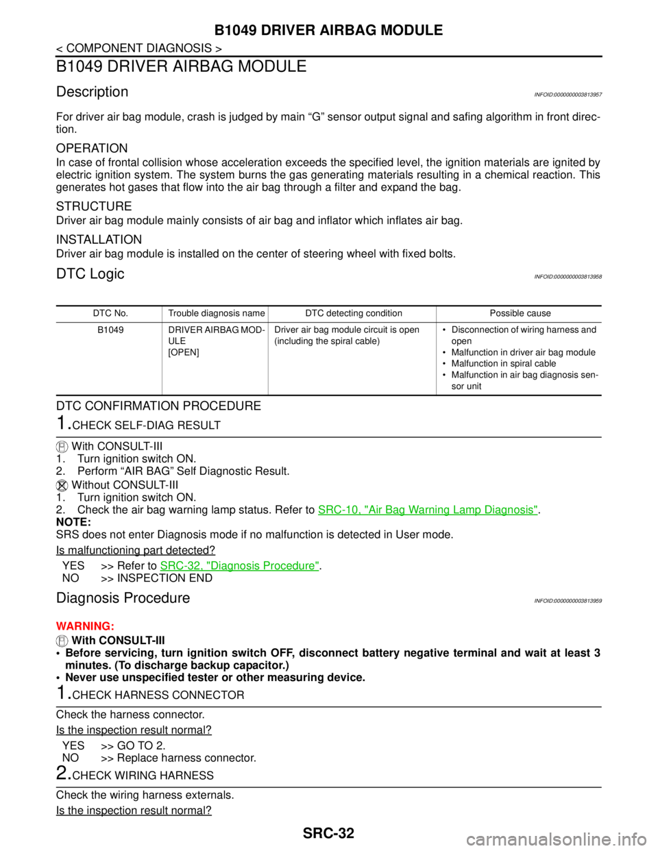
DTC No. Trouble diagnosis name DTC detecting condition Possible cause
B1049 DRIVER AIRBAG MOD-
ULE
[OPEN]Driver air bag module circuit is open
(including the spiral cable) Disconnection of wiring harness and
open
Malfunction in driver air bag module
Malfunction in spiral cable
Malfunction in air bag diagnosis sen-
sor unit
Page 4276 of 5121
B1049 DRIVER AIRBAG MODULE
SRC-33
< COMPONENT DIAGNOSIS >
C
D
E
F
G
I
J
K
L
MA
B
SRC
N
O
P
YES >> GO TO 3.
NO >> Replace wiring harness.
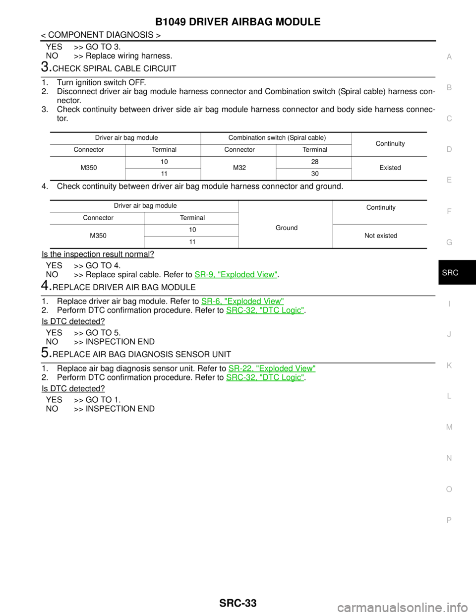
3.CHECK SPIRAL CABLE CIRCUIT
1. Turn ignition switch OFF.
2. Disconnect driver air bag module harness connector and Combination switch (Spiral cable) harness con-
nector.
3. Check continuity between driver side air bag module harness connector and body side harness connec-
tor.
4. Check continuity between driver air bag module harness connector and ground.
Is the inspection result normal?
YES >> GO TO 4.
NO >> Replace spiral cable. Refer to SR-9, "
Exploded View".
4.REPLACE DRIVER AIR BAG MODULE
1. Replace driver air bag module. Refer to SR-6, "
Exploded View"
2. Perform DTC confirmation procedure. Refer to SRC-32, "DTC Logic".
Is DTC detected?
YES >> GO TO 5.
NO >> INSPECTION END
5.REPLACE AIR BAG DIAGNOSIS SENSOR UNIT
1. Replace air bag diagnosis sensor unit. Refer to SR-22, "
Exploded View"
2. Perform DTC confirmation procedure. Refer to SRC-32, "DTC Logic".
Is DTC detected?
YES >> GO TO 1.
NO >> INSPECTION END
Driver air bag module Combination switch (Spiral cable)
Continuity
Connector Terminal Connector Terminal
M35010
M3228
Existed
11 3 0
Driver air bag module
GroundContinuity
Connector Terminal
M35010
Not existed
11
Page 4277 of 5121
SRC-34
< COMPONENT DIAGNOSIS >
B1050 DRIVER AIRBAG MODULE
B1050 DRIVER AIRBAG MODULE
DescriptionINFOID:0000000003813960
For driver air bag module, crash is judged by main “G” sensor output signal and safing algorithm in front direc-
tion.
OPERATION
In case of frontal collision whose acceleration exceeds the specified level, the ignition materials are ignited by
electric ignition system. The system burns the gas generating materials resulting in a chemical reaction. This
generates hot gases that flow into the air bag through a filter and expand the bag.
STRUCTURE
Driver air bag module mainly consists of air bag and inflator which inflates air bag.
INSTALLATION
Driver air bag module is installed on the center of steering wheel with fixed bolts.
DTC LogicINFOID:0000000003813961
DTC CONFIRMATION PROCEDURE
1.CHECK SELF-DIAG RESULT
With CONSULT-III
1. Turn ignition switch ON.
2. Perform “AIR BAG” Self Diagnostic Result.
Without CONSULT-III
1. Turn ignition switch ON.
2. Check the air bag warning lamp status. Refer to SRC-10, "
Air Bag Warning Lamp Diagnosis".
NOTE:
SRS does not enter Diagnosis mode if no malfunction is detected in User mode.
Is malfunctioning part detected?
YES >> Refer to SRC-34, "Diagnosis Procedure".
NO >> INSPECTION END
Diagnosis ProcedureINFOID:0000000003813962
WARNING:
Before servicing, turn ignition switch OFF, disconnect battery negative terminal and wait at least 3
minutes. (To discharge backup capacitor.)
Never use unspecified tester or other measuring device.
1.CHECK HARNESS CONNECTOR
Check the harness connector.
Is the inspection result normal?
YES >> GO TO 2.
NO >> Replace harness connector.
2.CHECK WIRING HARNESS
Check the wiring harness externals.
Is the inspection result normal?
YES >> GO TO 3.
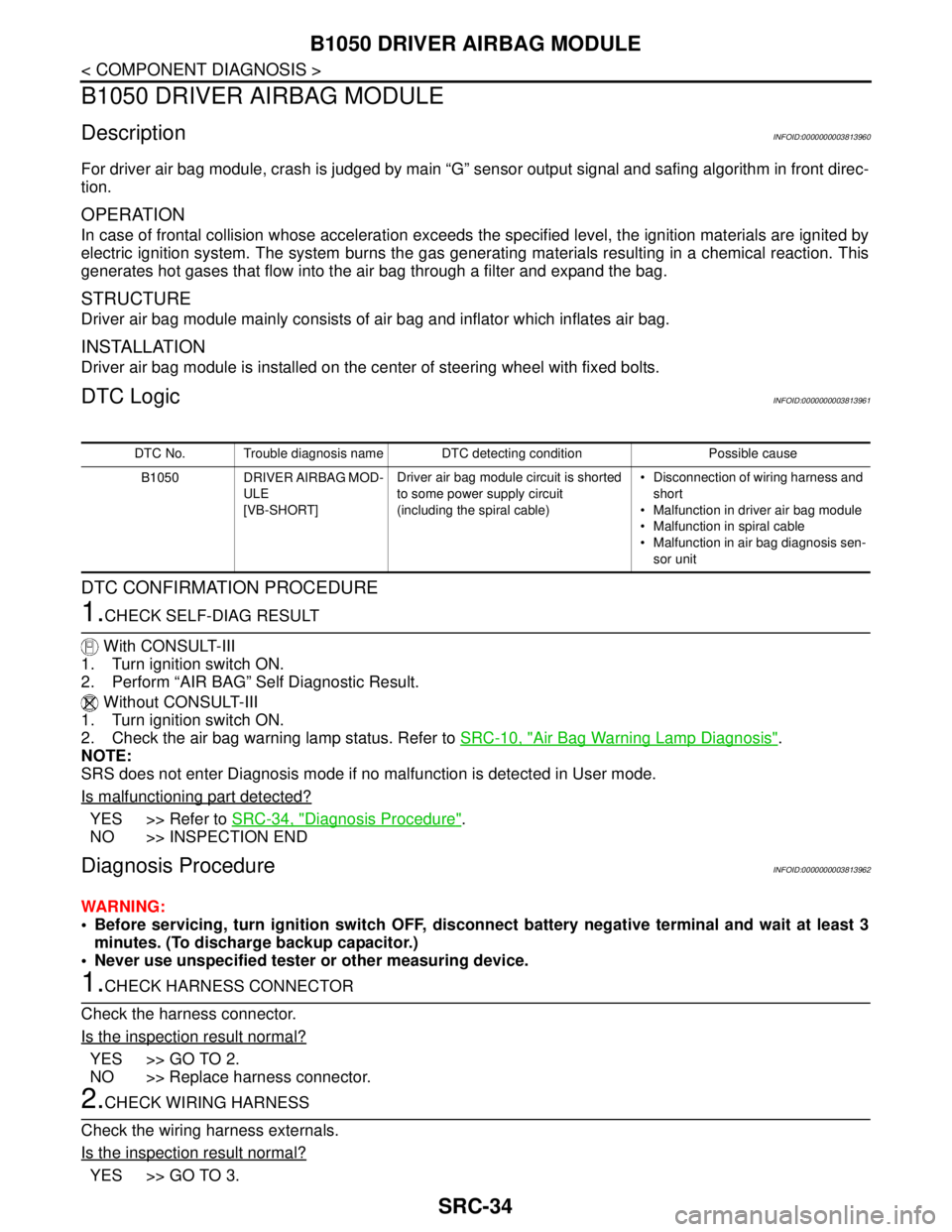
DTC No. Trouble diagnosis name DTC detecting condition Possible cause
B1050 DRIVER AIRBAG MOD-
ULE
[VB-SHORT]Driver air bag module circuit is shorted
to some power supply circuit
(including the spiral cable) Disconnection of wiring harness and
short
Malfunction in driver air bag module
Malfunction in spiral cable
Malfunction in air bag diagnosis sen-
sor unit