tire type NISSAN TEANA 2008 User Guide
[x] Cancel search | Manufacturer: NISSAN, Model Year: 2008, Model line: TEANA, Model: NISSAN TEANA 2008Pages: 5121, PDF Size: 69.03 MB
Page 3211 of 5121
CHASSIS MAINTENANCE
MA-23
< ON-VEHICLE MAINTENANCE >
C
D
E
F
G
H
I
J
K
L
MB
MAN
OA
CHASSIS MAINTENANCE
HEADLAMP AIMING ADJUSTMENT (XENON TYPE)
HEADLAMP AIMING ADJUSTMENT (XENON TYPE) : DescriptionINFOID:0000000003862420
PREPARATION BEFORE ADJUSTING
NOTE:
For details, refer to the regulations in your own country.
Perform aiming if the vehicle front body has been repaired and/or the headlamp assembly has been
replaced.
Before performing aiming adjustment, check the following. Adjust the tire pressure to the specification.
Fill with fuel, engine coolant and each oil.
Maintain the unloaded vehicle condition. (Remove luggage from the passenger compartment and the trunk
room.)
NOTE:
Do not remove the temporary tire, jack and on-vehicle tool.
Wipe out dirt on the headlamp.
CAUTION:
Never use organic solvent (thinner, gasoline etc.)
Ride alone on the driver seat.
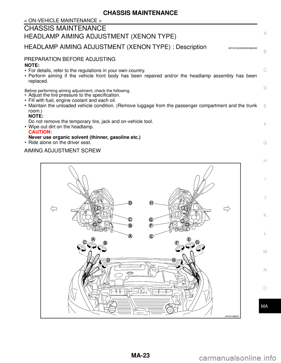
AIMING ADJUSTMENT SCREW
JPLIA1085ZZ
Page 3215 of 5121
CHASSIS MAINTENANCE
MA-27
< ON-VEHICLE MAINTENANCE >
C
D
E
F
G
H
I
J
K
L
MB
MAN
OA
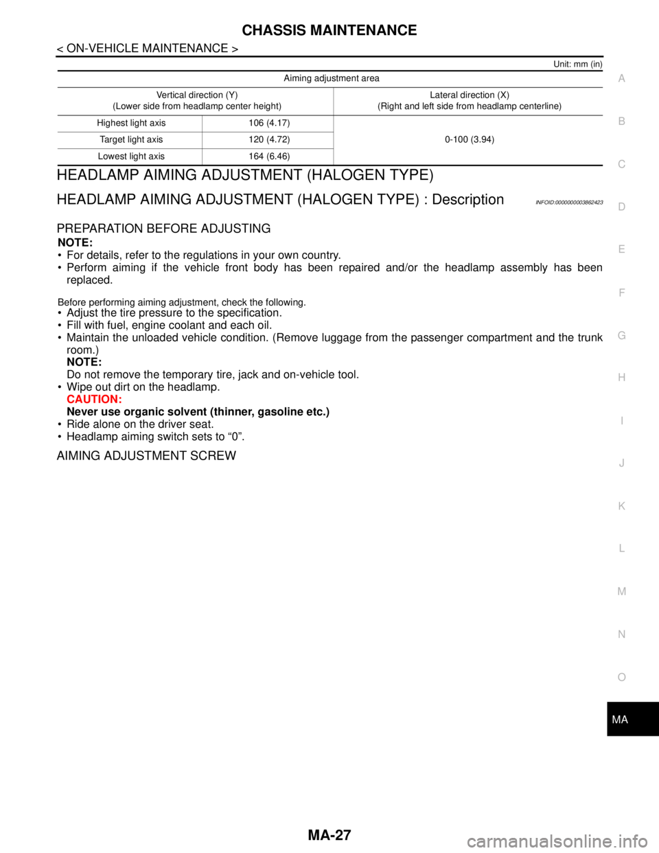
Unit: mm (in)
HEADLAMP AIMING ADJUSTMENT (HALOGEN TYPE)
HEADLAMP AIMING ADJUSTMENT (HALOGEN TYPE) : DescriptionINFOID:0000000003862423
PREPARATION BEFORE ADJUSTING
NOTE:
For details, refer to the regulations in your own country.
Perform aiming if the vehicle front body has been repaired and/or the headlamp assembly has been
replaced.
Before performing aiming adjustment, check the following.
Adjust the tire pressure to the specification.
Fill with fuel, engine coolant and each oil.
Maintain the unloaded vehicle condition. (Remove luggage from the passenger compartment and the trunk
room.)
NOTE:
Do not remove the temporary tire, jack and on-vehicle tool.
Wipe out dirt on the headlamp.
CAUTION:
Never use organic solvent (thinner, gasoline etc.)
Ride alone on the driver seat.
Headlamp aiming switch sets to “0”.
AIMING ADJUSTMENT SCREW
Aiming adjustment area
Vertical direction (Y)
(Lower side from headlamp center height)Lateral direction (X)
(Right and left side from headlamp centerline)
Highest light axis 106 (4.17)
0-100 (3.94) Target light axis 120 (4.72)
Lowest light axis 164 (6.46)
Page 3821 of 5121
RF-90
< ON-VEHICLE REPAIR >
SUNROOF UNIT ASSEMBLY
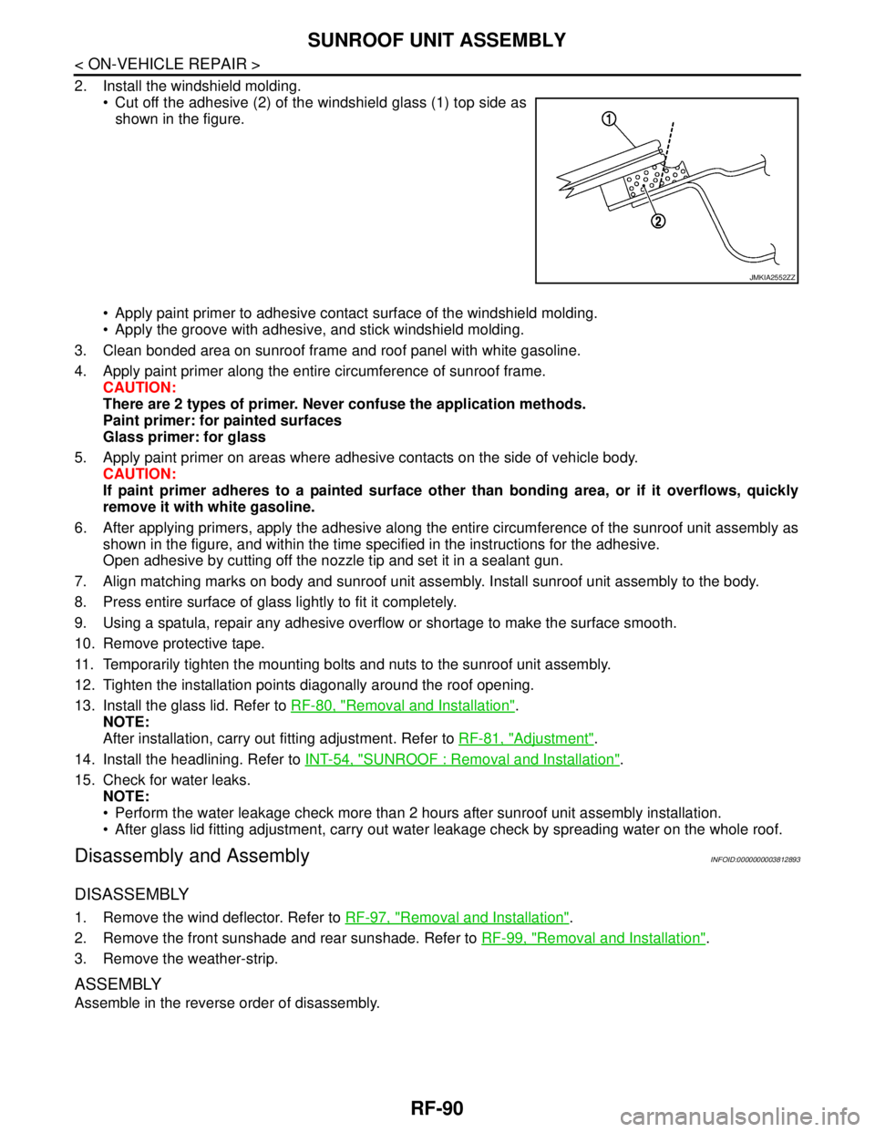
2. Install the windshield molding.
Cut off the adhesive (2) of the windshield glass (1) top side as
shown in the figure.
Apply paint primer to adhesive contact surface of the windshield molding.
Apply the groove with adhesive, and stick windshield molding.
3. Clean bonded area on sunroof frame and roof panel with white gasoline.
4. Apply paint primer along the entire circumference of sunroof frame.
CAUTION:
There are 2 types of primer. Never confuse the application methods.
Paint primer: for painted surfaces
Glass primer: for glass
5. Apply paint primer on areas where adhesive contacts on the side of vehicle body.
CAUTION:
If paint primer adheres to a painted surface other than bonding area, or if it overflows, quickly
remove it with white gasoline.
6. After applying primers, apply the adhesive along the entire circumference of the sunroof unit assembly as
shown in the figure, and within the time specified in the instructions for the adhesive.
Open adhesive by cutting off the nozzle tip and set it in a sealant gun.
7. Align matching marks on body and sunroof unit assembly. Install sunroof unit assembly to the body.
8. Press entire surface of glass lightly to fit it completely.
9. Using a spatula, repair any adhesive overflow or shortage to make the surface smooth.
10. Remove protective tape.
11. Temporarily tighten the mounting bolts and nuts to the sunroof unit assembly.
12. Tighten the installation points diagonally around the roof opening.
13. Install the glass lid. Refer to RF-80, "
Removal and Installation".
NOTE:
After installation, carry out fitting adjustment. Refer to RF-81, "
Adjustment".
14. Install the headlining. Refer to INT-54, "
SUNROOF : Removal and Installation".
15. Check for water leaks.
NOTE:
Perform the water leakage check more than 2 hours after sunroof unit assembly installation.
After glass lid fitting adjustment, carry out water leakage check by spreading water on the whole roof.
Disassembly and AssemblyINFOID:0000000003812893
DISASSEMBLY
1. Remove the wind deflector. Refer to RF-97, "Removal and Installation".
2. Remove the front sunshade and rear sunshade. Refer to RF-99, "
Removal and Installation".
3. Remove the weather-strip.
ASSEMBLY
Assemble in the reverse order of disassembly.
JMKIA2552ZZ
Page 3823 of 5121
RF-92
< ON-VEHICLE REPAIR >
FRONT SUNROOF GLASS
5. Apply protective tape around the roof panel and windshield to protect the surface from damage.
6. Remove weather-strip.
7. Cut adhesive.
Pass piano wire though the adhesive with a wire pierce.
Tie both ends of piano wire to wire grip.
Pull piano wire in turn and cut off adhesive.
8. Remove front sunroof glass from vehicle.
WARNING:
Always use safety glasses and heavy gloves to help prevent glass splinters from entering your eyes
or cutting your hands when cutting the glass from the vehicle.
CAUTION:
Never reuse the front sunroof glass which has been removed once.
INSTALLATION
WARNING:
Keep heat and open flames away as primers and adhesive are flammable.
The materials contained in the kit are harmful if swallowed, and may irritate skin and eyes. Never let
them in contact with the skin and eyes.
Use in an open, well ventilated location. Never breathe the vapors. They may be harmful if inhaled.
Move immediately to an area with fresh air if affected by vapor inhalation.
NOTE:
Use a genuine Nissan Urethane Adhesive Kit (if available) or an equivalent and follow the instructions fur-
nished with it.
Inform the customer that the vehicle should remain stationary until the urethane adhesive has completely
cured (approximately 24 hours). Curing time varies with temperature and humidity.
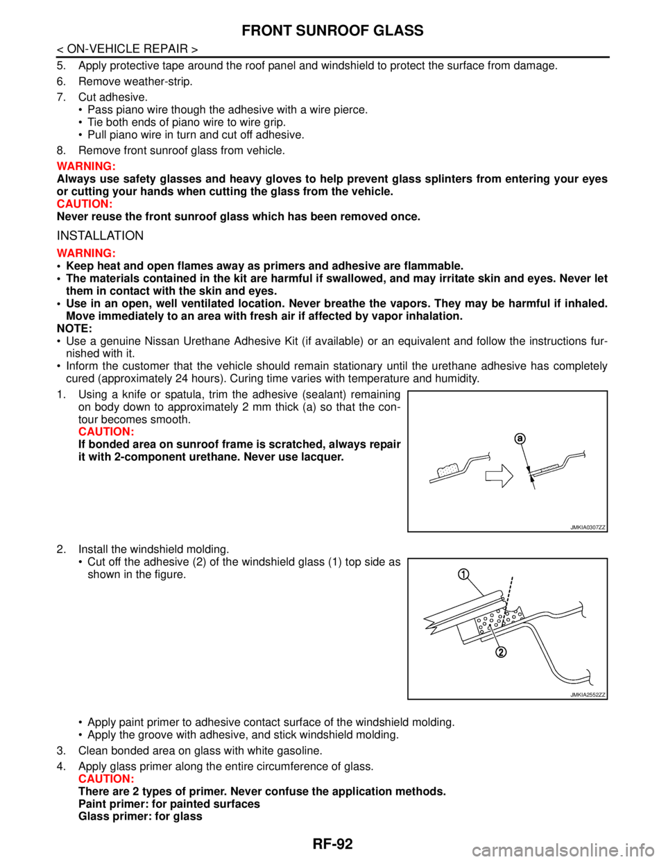
1. Using a knife or spatula, trim the adhesive (sealant) remaining
on body down to approximately 2 mm thick (a) so that the con-
tour becomes smooth.
CAUTION:
If bonded area on sunroof frame is scratched, always repair
it with 2-component urethane. Never use lacquer.
2. Install the windshield molding.
Cut off the adhesive (2) of the windshield glass (1) top side as
shown in the figure.
Apply paint primer to adhesive contact surface of the windshield molding.
Apply the groove with adhesive, and stick windshield molding.
3. Clean bonded area on glass with white gasoline.
4. Apply glass primer along the entire circumference of glass.
CAUTION:
There are 2 types of primer. Never confuse the application methods.
Paint primer: for painted surfaces
Glass primer: for glass
JMKIA0307ZZ
JMKIA2552ZZ
Page 3826 of 5121
REAR SUNROOF GLASS
RF-95
< ON-VEHICLE REPAIR >
C
D
E
F
G
H
I
J
L
MA
B
RF
N
O
P
5. Remove weather-strip.
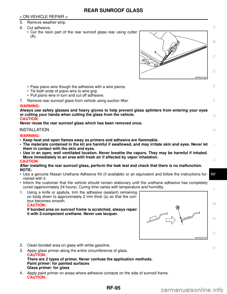
6. Cut adhesive.
Cut the resin part of the rear sunroof glass rear using cutter
(A).
Pass piano wire though the adhesive with a wire pierce.
Tie both ends of piano wire to wire grip.
Pull piano wire in turn and cut off adhesive.
7. Remove rear sunroof glass from vehicle using suction lifter.
WARNING:
Always use safety glasses and heavy gloves to help prevent glass splinters from entering your eyes
or cutting your hands when cutting the glass from the vehicle.
CAUTION:
Never reuse the rear sunroof glass which has been removed once.
INSTALLATION
WARNING:
Keep heat and open flames away as primers and adhesive are flammable.
The materials contained in the kit are harmful if swallowed, and may irritate skin and eyes. Never let
them in contact with the skin and eyes.
Use in an open, well ventilated location. Never breathe the vapors. They may be harmful if inhaled.
Move immediately to an area with fresh air if affected by vapor inhalation.
CAUTION:
After installing the rear sunroof glass, perform the leak test and check that there is no malfunction.
NOTE:
Use a genuine Nissan Urethane Adhesive Kit (if available) or an equivalent and follow the instructions fur-
nished with it.
Inform the customer that the vehicle should remain stationary until the urethane adhesive has completely
cured (approximately 24 hours). Curing time varies with temperature and humidity.
1. Using a knife or spatula, trim the adhesive (sealant) remaining
on body down to approximately 2 mm thick (a) so that the con-
tour becomes smooth.
CAUTION:
If bonded area on sunroof frame is scratched, always repair
it with 2-component urethane. Never use lacquer.
2. Clean bonded area on glass with white gasoline.
3. Apply glass primer along the entire circumference of glass.
CAUTION:
There are 2 types of primer. Never confuse the application methods.
Paint primer: for painted surfaces
Glass primer: for glass
4. Apply paint primer on areas where adhesive contacts on the side of sunroof frame.
CAUTION:
JMKIA2510ZZ
JMKIA0307ZZ
Page 3848 of 5121
RSU-16
< REMOVAL AND INSTALLATION >
REAR SUSPENSION ARM
REMOVAL AND INSTALLATION
REAR SUSPENSION ARM
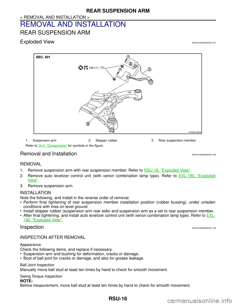
Exploded ViewINFOID:0000000003811157
Removal and InstallationINFOID:0000000003811158
REMOVAL
1. Remove suspension arm with rear suspension member. Refer to RSU-18, "Exploded View".
2. Remove auto levelizer control unit (with xenon combination lamp type). Refer to EXL-190, "
Exploded
View".
3. Remove suspension arm.
INSTALLATION
Note the following, and install in the reverse order of removal.
Perform final tightening of rear suspension member installation position (rubber bussing), under unladen
conditions with tires on level ground.
Install stopper rubber (suspension arm rear side) and suspension arm as a set to rear suspension member.
After final tightening, and install auto levelizer control unit (with xenon combination lamp type). Refer to EXL-
190, "Exploded View".
InspectionINFOID:0000000003811159
INSPECTION AFTER REMOVAL
Appearance
Check the following items, and replace if necessary.
Suspension arm and bushing for deformation, cracks or damage.
Boot of ball joint for cracks or damage, and also for grease leakage.
Ball Joint Inspection
Manually move ball stud at least ten times by hand to check for smooth movement.
Swing Torque Inspection
NOTE:
Before measurement, move ball stud at least ten times by hand to check for smooth movement.
1. Suspension arm 2. Stopper rubber 3. Rear suspension member
Refer to GI-4, "
Components" for symbols in the figure.
JPEIB0106GB
Page 3850 of 5121
RSU-18
< REMOVAL AND INSTALLATION >
REAR SUSPENSION MEMBER
REAR SUSPENSION MEMBER
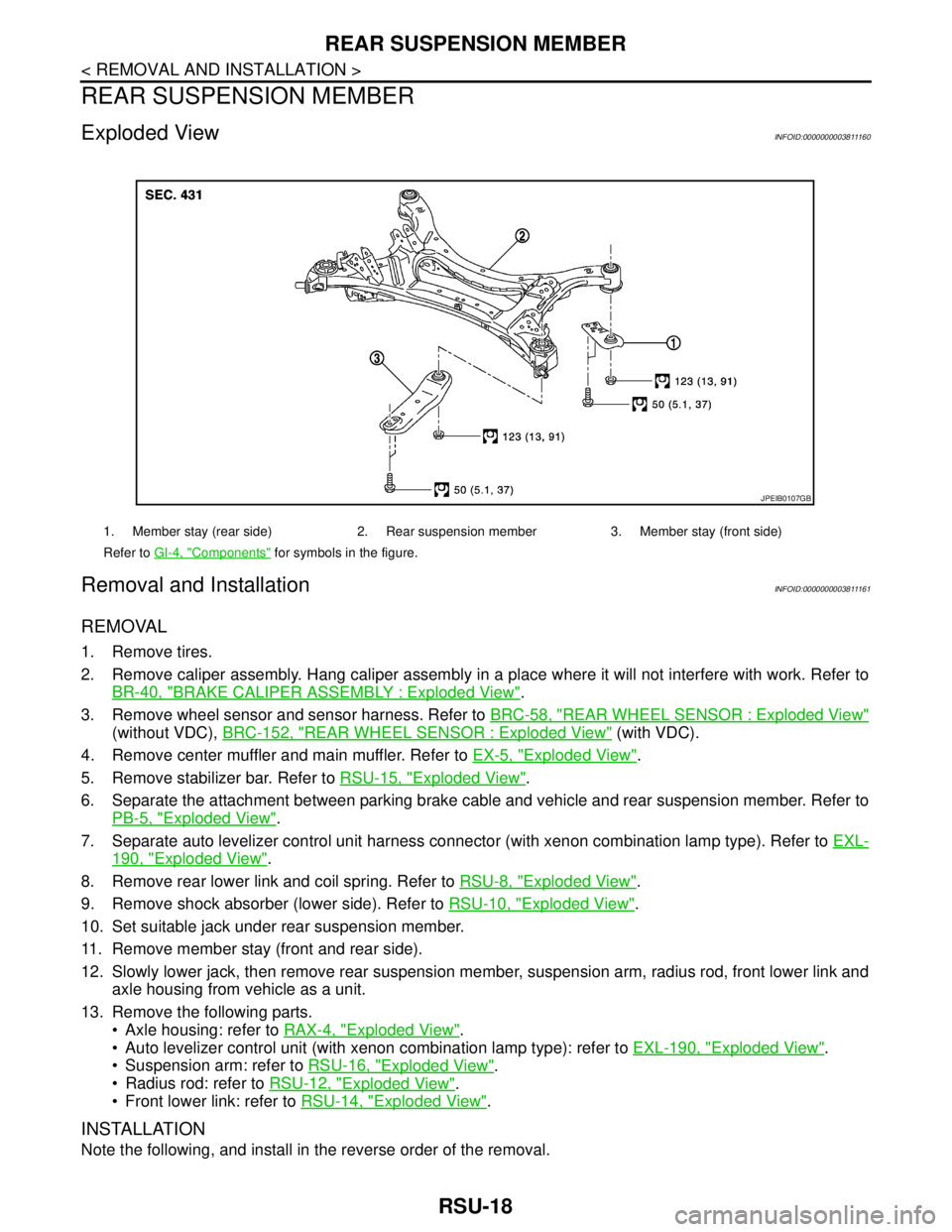
Exploded ViewINFOID:0000000003811160
Removal and InstallationINFOID:0000000003811161
REMOVAL
1. Remove tires.
2. Remove caliper assembly. Hang caliper assembly in a place where it will not interfere with work. Refer to
BR-40, "
BRAKE CALIPER ASSEMBLY : Exploded View".
3. Remove wheel sensor and sensor harness. Refer to BRC-58, "
REAR WHEEL SENSOR : Exploded View"
(without VDC), BRC-152, "REAR WHEEL SENSOR : Exploded View" (with VDC).
4. Remove center muffler and main muffler. Refer to EX-5, "
Exploded View".
5. Remove stabilizer bar. Refer to RSU-15, "
Exploded View".
6. Separate the attachment between parking brake cable and vehicle and rear suspension member. Refer to
PB-5, "
Exploded View".
7. Separate auto levelizer control unit harness connector (with xenon combination lamp type). Refer to EXL-
190, "Exploded View".
8. Remove rear lower link and coil spring. Refer to RSU-8, "
Exploded View".
9. Remove shock absorber (lower side). Refer to RSU-10, "
Exploded View".
10. Set suitable jack under rear suspension member.
11. Remove member stay (front and rear side).
12. Slowly lower jack, then remove rear suspension member, suspension arm, radius rod, front lower link and
axle housing from vehicle as a unit.
13. Remove the following parts.
Axle housing: refer to RAX-4, "
Exploded View".
Auto levelizer control unit (with xenon combination lamp type): refer to EXL-190, "
Exploded View".
Suspension arm: refer to RSU-16, "
Exploded View".
Radius rod: refer to RSU-12, "
Exploded View".
Front lower link: refer to RSU-14, "
Exploded View".
INSTALLATION
Note the following, and install in the reverse order of the removal.
1. Member stay (rear side) 2. Rear suspension member 3. Member stay (front side)
Refer to GI-4, "
Components" for symbols in the figure.
JPEIB0107GB
Page 3854 of 5121
SB-2
< PRECAUTION >
PRECAUTIONS
PRECAUTION
PRECAUTIONS
Precaution for Supplemental Restraint System (SRS) "AIR BAG" and "SEAT BELT
PRE-TENSIONER"
INFOID:0000000003949049
The Supplemental Restraint System such as “AIR BAG” and “SEAT BELT PRE-TENSIONER”, used along
with a front seat belt, helps to reduce the risk or severity of injury to the driver and front passenger for certain
types of collision. Information necessary to service the system safely is included in the “SRS AIRBAG” and
“SEAT BELT” of this Service Manual.
WARNING:
• To avoid rendering the SRS inoperative, which could increase the risk of personal injury or death in
the event of a collision which would result in air bag inflation, all maintenance must be performed by
an authorized NISSAN/INFINITI dealer.
Improper maintenance, including incorrect removal and installation of the SRS, can lead to personal
injury caused by unintentional activation of the system. For removal of Spiral Cable and Air Bag
Module, see the “SRS AIRBAG”.
Never use electrical test equipment on any circuit related to the SRS unless instructed to in this Ser-
vice Manual. SRS wiring harnesses can be identified by yellow and/or orange harnesses or harness
connectors.
Precaution for Seat Belt ServiceINFOID:0000000003848851
CAUTION:
Before removing the front seat belt pre-tensioner assembly, turn the ignition switch OFF, disconnect
both battery cables and wait at least 3 minutes.
Never use electrical test equipment for front seat belt pre-tensioner connector.
After replacing or reinstalling front seat belt pre-tensioner assembly, or reconnecting front seat belt
pre-tensioner connector, check the system function. Refer to SRC-10, "
Diagnosis Description".
Deploy front seat belt pre-tensioner assembly before disposing. Refer to SR-25, "
Caution for Air Bag
Module and Seat Belt Pre-tensioner"
Never use disassembled buckle or seat belt assembly.
Replace anchor bolts if they are deformed or worn out.
Never oil tongue and buckle.
If any component of seat belt assembly is questionable, never repair. Replace the entire seat belt
assembly.
If webbing is cut, frayed or damaged, replace seat belt assembly.
When replacing seat belt assembly, use a Genuine NISSAN seat belt assembly.
AFTER A COLLISION
WARNING:
Inspect all seat belt assemblies including retractors and attached hardware after any collision.
NISSAN recommends that all seat belt assemblies in use during a collision be replaced unless the col-
lision was minor and the belts show no damage and continue to operate properly. Not doing so could
result in serious personal injury in an accident. Seat belt assemblies not in use during a collision
should also be replaced if either damage or improper operation is noted. Seat belt pre-tensioners
should be replaced even if the seat belts are not in use during a frontal collision in which the air bags
are deployed.
Replace any seat belt assembly (including anchor bolts) if:
The seat belt is in use at the time of a collision (except for minor collisions and the belts, retractors and buck-
les show no damage and continue to operate properly).
The seat belt is damaged in an accident (i.e. torn webbing, bent retractor or guide).
The seat belt attaching point is damaged in an accident. Inspect the seat belt attaching area for damage or
distortion and repair as necessary before installing a new seat belt assembly.
Anchor bolts are deformed or worn out.
The front seat belt pre-tensioner must be replaced even if the seat belts are not in use during the collision in
which the air bags are deployed.
Page 3856 of 5121
SB-4
< ON-VEHICLE REPAIR >
FRONT SEAT BELT
6. Remove the clip fixing the seat belt and check that the webbing returns smoothly.
6. Repeat steps above as necessary to check the other seat belts.
SEAT BELT RETRACTOR ON-VEHICLE CHECK
Emergency Locking Retractors (ELR) and Automatic Locking Retractors (ALR)
NOTE:
All seat belt retractors are Emergency Locking Retractors (ELR) type. In an emergency (sudden stop) the
retractor will lock and prevent the webbing from extending any further. All 3-point type seat belt retractors
except the driver seat belt also have an Automatic Locking Retractors (ALR) mode. The ALR mode (also
called child restraint mode) is used when installing child seats. The ALR mode is activated when the seat belt
is fully extended. When the webbing is then retracted partially, the ALR mode automatically locks the seat belt
in a specific position so the webbing cannot be extended any further. To cancel the ALR mode, allow the seat
belt to fully wind back into the retractor.
Check the seat belt retractors with the following test(s) to determine if a retractor assembly is operating prop-
erly.
ELR Function Stationary Check
Grasp the shoulder webbing and pull forward quickly. The retractor should lock and prevent the belt from
extending further.
ALR Function Stationary Check
1. Pull out the entire length of seat belt from retractor until a click is heard.
2. Retract the webbing partially. A clicking noise should be heard as the webbing retracts indicating that the
retractor is in the Automatic Locking Retractors (ALR) mode.
3. Grasp the seat belt and try to pull out the retractor. The webbing must lock and not extend any further. If
NG, replace the retractor assembly.
4. Allow the entire length of the webbing to retract to cancel the automatic locking mode.
ELR Function Moving Check
WARNING:
Perform the following test in a safe, open area clear of other vehicles and obstructions (for example, a
large, empty parking lot). Road surface must be paved and dry. Never perform the following test on
wet or gravel roads or on public streets and highways. This could result in an accident and serious
personal injury. The driver and passenger must be prepared to brace themselves in the event that the
retractor does not lock.
1. Fasten driver seat belt. Buckle a passenger into the seat for the belt that is to be tested.
2. Proceed to the designated safe area.
3. Drive the vehicle at approximately 16 km/h (10 MPH). Notify any passengers of a pending sudden stop
and the driver and passenger must be prepared to brace themselves in the event that the retractor does
not lock, apply brakes firmly and make a very hard stop.
During stopping, seat belts should lock and not be extended. If the seat belt retractor assembly does not lock,
perform the retractor off-vehicle check.
SEAT BELT RETRACTOR OFF-VEHICLE CHECK
1. Remove the seat belt retractor.
Remove the front seat belt assembly, refer to SB-5, "
SEAT BELT RETRACTOR : Removal and Installa-
tion".
2. Slowly pull out webbing while tilting the retractor assembly forward from the mounted position without
twisting the retractor assembly as shown in the illustration.
Page 4390 of 5121
PRECAUTIONS
SRC-147
< PRECAUTION >
C
D
E
F
G
I
J
K
L
MA
B
SRC
N
O
P
PRECAUTION
PRECAUTIONS
Precaution for Supplemental Restraint System (SRS) "AIR BAG" and "SEAT BELT
PRE-TENSIONER"
INFOID:0000000003814141
The Supplemental Restraint System such as “AIR BAG” and “SEAT BELT PRE-TENSIONER”, used along
with a front seat belt, helps to reduce the risk or severity of injury to the driver and front passenger for certain
types of collision. Information necessary to service the system safely is included in the “SRS AIRBAG” and
“SEAT BELT” of this Service Manual.
WARNING:
To avoid rendering the SRS inoperative, which could increase the risk of personal injury or death in
the event of a collision which would result in air bag inflation, all maintenance must be performed by
an authorized NISSAN/INFINITI dealer.
Improper maintenance, including incorrect removal and installation of the SRS, can lead to personal
injury caused by unintentional activation of the system. For removal of Spiral Cable and Air Bag
Module, see the “SRS AIRBAG”.
Never use electrical test equipment on any circuit related to the SRS unless instructed to in this Ser-
vice Manual. SRS wiring harnesses can be identified by yellow and/or orange harnesses or harness
connectors.
ServiceINFOID:0000000003814109
Do not use electrical test equipment to check SRS circuits unless instructed to in this Service Manual.
Before servicing the SRS, turn ignition switch OFF, disconnect battery negative terminal and wait at least 3
minutes.
For approximately 3 minutes after the battery negative terminal is removed, it is still possible for the air bag
and seat belt pre-tensioner to deploy. Therefore, do not work on any SRS connectors or wires until at least 3
minutes have elapsed.
Diagnosis sensor unit must always be installed with their arrow marks “⇐” pointing towards the front of the
vehicle for proper operation. Also check diagnosis sensor unit for cracks, deformities or rust before installa-
tion and replace as required.
The spiral cable must be aligned in the neutral position since its rotations are limited. Do not turn steering
wheel and column after removal of steering gear.
Handle air bag module carefully. Always place driver and front passenger air bag modules with the pad side
facing upward and seat mounted front side air bag module standing with the stud bolt side facing down.
Conduct self-diagnosis to check entire SRS for proper function after replacing any components.
After air bag inflates, the front instrument panel assembly should be replaced if damaged.
Always replace instrument panel pad following front passenger air bag deployment.