wheel bolt torque NISSAN TEANA 2008 User Guide
[x] Cancel search | Manufacturer: NISSAN, Model Year: 2008, Model line: TEANA, Model: NISSAN TEANA 2008Pages: 5121, PDF Size: 69.03 MB
Page 2448 of 5121
FAX-20
< ON-VEHICLE REPAIR >
FRONT DRIVE SHAFT
Always replace differential side oil seal with new one when installing drive shaft. Refer to TM-162, "Exploded
View" (CVT: RE0F09B), TM-325, "Exploded View" (CVT: RE0F10A).
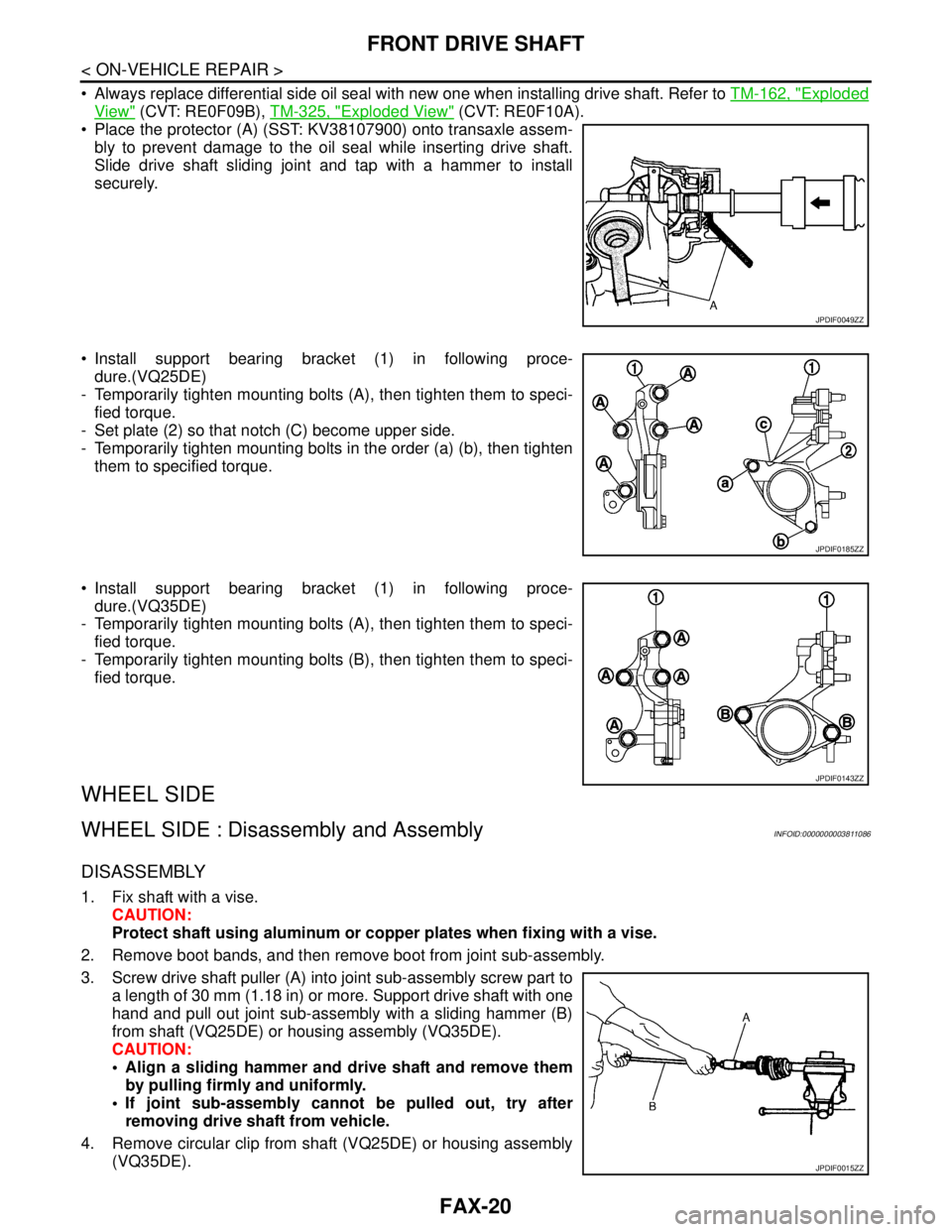
Place the protector (A) (SST: KV38107900) onto transaxle assem-
bly to prevent damage to the oil seal while inserting drive shaft.
Slide drive shaft sliding joint and tap with a hammer to install
securely.
Install support bearing bracket (1) in following proce-
dure.(VQ25DE)
- Temporarily tighten mounting bolts (A), then tighten them to speci-
fied torque.
- Set plate (2) so that notch (C) become upper side.
- Temporarily tighten mounting bolts in the order (a) (b), then tighten
them to specified torque.
Install support bearing bracket (1) in following proce-
dure.(VQ35DE)
- Temporarily tighten mounting bolts (A), then tighten them to speci-
fied torque.
- Temporarily tighten mounting bolts (B), then tighten them to speci-
fied torque.
WHEEL SIDE
WHEEL SIDE : Disassembly and AssemblyINFOID:0000000003811086
DISASSEMBLY
1. Fix shaft with a vise.
CAUTION:
Protect shaft using aluminum or copper plates when fixing with a vise.
2. Remove boot bands, and then remove boot from joint sub-assembly.
3. Screw drive shaft puller (A) into joint sub-assembly screw part to
a length of 30 mm (1.18 in) or more. Support drive shaft with one
hand and pull out joint sub-assembly with a sliding hammer (B)
from shaft (VQ25DE) or housing assembly (VQ35DE).
CAUTION:
Align a sliding hammer and drive shaft and remove them
by pulling firmly and uniformly.
If joint sub-assembly cannot be pulled out, try after
removing drive shaft from vehicle.
4. Remove circular clip from shaft (VQ25DE) or housing assembly
(VQ35DE).
JPDIF0049ZZ
JPDIF0185ZZ
JPDIF0143ZZ
JPDIF0015ZZ
Page 2479 of 5121
PREPARATION
FSU-5
< PREPARATION >
C
D
F
G
H
I
J
K
L
MA
B
FSU
N
O
P
PREPARATION
PREPARATION
Special Service ToolINFOID:0000000003812472
Commercial Service ToolINFOID:000000000381111 3
Tool number
Tool nameDescription
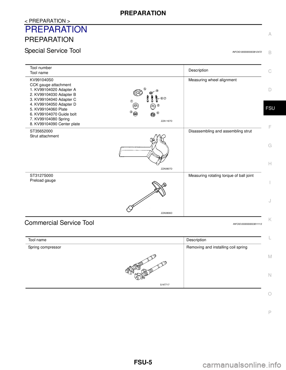
KV991040S0
CCK gauge attachment
1. KV99104020 Adapter A
2. KV99104030 Adapter B
3. KV99104040 Adapter C
4. KV99104050 Adapter D
5. KV99104060 Plate
6. KV99104070 Guide bolt
7. KV99104080 Spring
8. KV99104090 Center plateMeasuring wheel alignment
ST35652000
Strut attachmentDisassembling and assembling strut
ST3127S000
Preload gaugeMeasuring rotating torque of ball joint
ZZA1167D
ZZA0807D
ZZA0806D
Tool nameDescription
Spring compressor Removing and installing coil spring
S-NT717
Page 2486 of 5121
FSU-12
< ON-VEHICLE REPAIR >
TRANSVERSE LINK
TRANSVERSE LINK
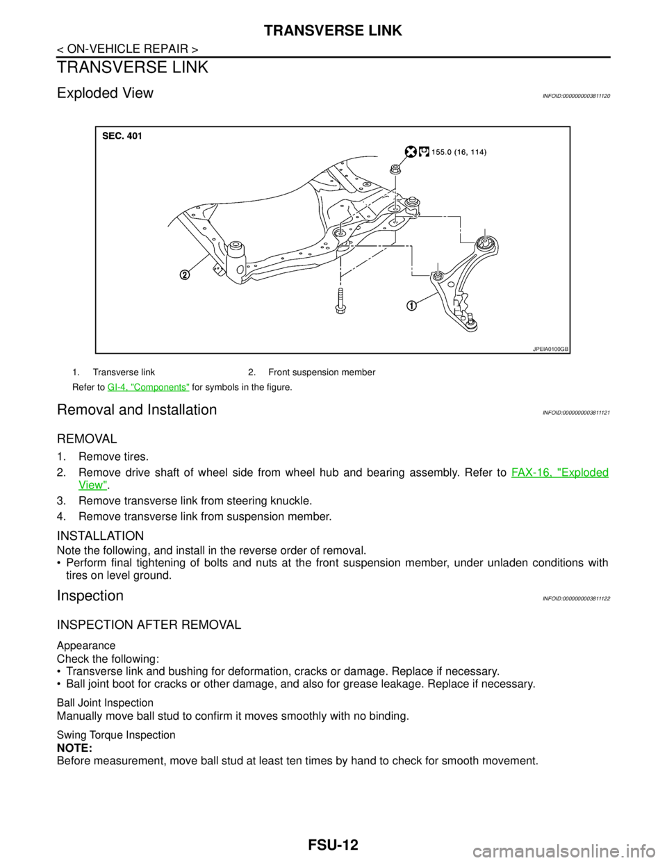
Exploded ViewINFOID:0000000003811120
Removal and InstallationINFOID:0000000003811121
REMOVAL
1. Remove tires.
2. Remove drive shaft of wheel side from wheel hub and bearing assembly. Refer to FAX-16, "
Exploded
View".
3. Remove transverse link from steering knuckle.
4. Remove transverse link from suspension member.
INSTALLATION
Note the following, and install in the reverse order of removal.
Perform final tightening of bolts and nuts at the front suspension member, under unladen conditions with
tires on level ground.
InspectionINFOID:0000000003811122
INSPECTION AFTER REMOVAL
Appearance
Check the following:
Transverse link and bushing for deformation, cracks or damage. Replace if necessary.
Ball joint boot for cracks or other damage, and also for grease leakage. Replace if necessary.
Ball Joint Inspection
Manually move ball stud to confirm it moves smoothly with no binding.
Swing Torque Inspection
NOTE:
Before measurement, move ball stud at least ten times by hand to check for smooth movement.
1. Transverse link 2. Front suspension member
Refer to GI-4, "
Components" for symbols in the figure.
JPEIA0100GB
Page 2494 of 5121

GI-1
GENERAL INFORMATION
C
D
E
F
G
H
I
J
K
L
MB
GI
SECTION GI
N
O
P
CONTENTS
GENERAL INFORMATION
HOW TO USE THIS MANUAL ......................3
HOW TO USE THIS MANUAL ............................3
Description ................................................................3
Terms ........................................................................3
Units ..........................................................................3
Contents ....................................................................3
Relation between Illustrations and Descriptions .......4
Components ..............................................................4
HOW TO FOLLOW TROUBLE DIAGNOSES .....6
Description ................................................................6
How to Follow Test Groups in Trouble Diagnosis ......6
Key to Symbols Signifying Measurements or Pro-
cedures .....................................................................
7
HOW TO READ WIRING DIAGRAMS ................9
Connector Symbols ...................................................9
Sample/Wiring Diagram -Example- .........................10
Description ..............................................................11
ABBREVIATIONS ..............................................13
Abbreviation List ......................................................13
TIGHTENING TORQUE OF STANDARD
BOLTS ................................................................
14
Description ..............................................................14
Tightening Torque Table (New Standard Includ-
ed) ...........................................................................
14
TERMINOLOGY .................................................17
SAE J1930 Terminology List ...................................17
FEATURES OF NEW MODEL .....................21
IDENTIFICATION INFORMATION .....................21
Model Variation .......................................................21
Information About Identification or Model Code ......21
Dimensions .............................................................23
Wheels & Tires ........................................................23
PRECAUTION ..............................................24
PRECAUTIONS .................................................24
Description ...............................................................24
Precaution for Supplemental Restraint System
(SRS) "AIR BAG" and "SEAT BELT PRE-TEN-
SIONER" .................................................................
24
Precautions For Xenon Headlamp Service .............24
Precaution Necessary for Steering Wheel Rota-
tion after Battery Disconnect ...................................
24
Precaution for Procedure without Cowl Top Cover ....25
General Precautions ................................................25
Three Way Catalyst .................................................27
Multiport Fuel Injection System or Engine Control
System .....................................................................
27
Hoses ......................................................................27
Engine Oils ..............................................................28
Air Conditioning .......................................................28
Fuel ..........................................................................29
LIFTING POINT .................................................30
Commercial Service Tools .......................................30
Garage Jack and Safety Stand and 2-Pole Lift .......30
Board-On Lift ...........................................................31
TOW TRUCK TOWING .....................................32
Tow Truck Towing ...................................................32
Vehicle Recovery (Freeing a Stuck Vehicle) ...........32
BASIC INSPECTION ...................................34
SERVICE INFORMATION FOR ELECTRICAL
INCIDENT ..........................................................
34
Work Flow ................................................................34
Control Units and Electrical Parts ............................34
Intermittent Incident .................................................35
Circuit Inspection .....................................................37
CONSULT-III/GST CHECKING SYSTEM .........43
Description ...............................................................43
CONSULT-III Function and System Application*1 ....43
CONSULT-III/GST Data Link Connector (DLC)
Circuit ......................................................................
43
Page 3839 of 5121
WHEEL ALIGNMENT
RSU-7
< ON-VEHICLE MAINTENANCE >
C
D
F
G
H
I
J
K
L
MA
B
RSU
N
O
P
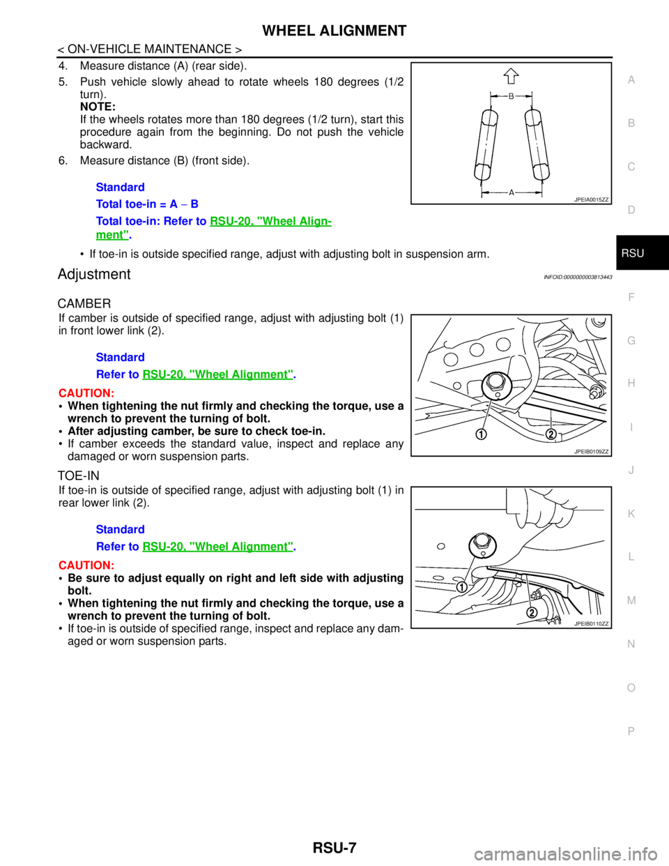
4. Measure distance (A) (rear side).
5. Push vehicle slowly ahead to rotate wheels 180 degrees (1/2
turn).
NOTE:
If the wheels rotates more than 180 degrees (1/2 turn), start this
procedure again from the beginning. Do not push the vehicle
backward.
6. Measure distance (B) (front side).
If toe-in is outside specified range, adjust with adjusting bolt in suspension arm.
AdjustmentINFOID:0000000003813443
CAMBER
If camber is outside of specified range, adjust with adjusting bolt (1)
in front lower link (2).
CAUTION:
When tightening the nut firmly and checking the torque, use a
wrench to prevent the turning of bolt.
After adjusting camber, be sure to check toe-in.
If camber exceeds the standard value, inspect and replace any
damaged or worn suspension parts.
TOE-IN
If toe-in is outside of specified range, adjust with adjusting bolt (1) in
rear lower link (2).
CAUTION:
Be sure to adjust equally on right and left side with adjusting
bolt.
When tightening the nut firmly and checking the torque, use a
wrench to prevent the turning of bolt.
If toe-in is outside of specified range, inspect and replace any dam-
aged or worn suspension parts.Standard
Total toe-in = A − B
Total toe-in: Refer to RSU-20, "
Wheel Align-
ment".
JPEIA0015ZZ
Standard
Refer to RSU-20, "
Wheel Alignment".
JPEIB0109ZZ
Standard
Refer to RSU-20, "
Wheel Alignment".
JPEIB0110ZZ
Page 4480 of 5121

TM-7
C
E
F
G
H
I
J
K
L
MA
B
TM
N
O
P Precaution for Supplemental Restraint System
(SRS) "AIR BAG" and "SEAT BELT PRE-TEN-
SIONER" ...............................................................
297
Precaution Necessary for Steering Wheel Rota-
tion after Battery Disconnect .................................
297
Precaution for Procedure without Cowl Top Cover ..298
Precaution for On Board Diagnosis (OBD) System
of CVT and Engine ................................................
298
Precaution for TCM and CVT Assembly Replace-
ment ......................................................................
298
Removal and Installation Procedure for CVT Unit
Connector ..............................................................
298
Precaution .............................................................299
Service Notice or Precaution .................................300
ATFTEMP COUNT Conversion Table ..................301
PREPARATION .........................................302
PREPARATION ................................................302
Special Service Tools ............................................302
Commercial Service Tools ....................................302
ON-VEHICLE MAINTENANCE ..................304
CVT FLUID .......................................................304
Inspection ..............................................................304
Changing ...............................................................305
STALL TEST ....................................................306
Inspection and Judgment ......................................306
LINE PRESSURE TEST ...................................308
Inspection and Judgment ......................................308
ROAD TEST .....................................................310
Description ............................................................310
Check before Engine Is Started ............................310
Check at Idle .........................................................311
Cruise Test ............................................................312
CVT POSITION .................................................314
Inspection and Adjustment ....................................314
ON-VEHICLE REPAIR ...............................315
TRANSMISSION CONTROL MODULE ...........315
Exploded View ......................................................315
Removal and Installation .......................................315
CONTROL DEVICE ..........................................317
Exploded View ......................................................317
Removal and Installation .......................................317
Inspection and Adjustment ....................................318
CONTROL CABLE ...........................................319
Exploded View ......................................................319
Removal and Installation .......................................319
Inspection and Adjustment ....................................320
OIL PAN ...........................................................321
Exploded View ......................................................321
Removal and Installation .......................................321
Inspection ..............................................................322
PRIMARY SPEED SENSOR ...........................323
Exploded View .......................................................323
Removal and Installation .......................................323
Inspection ..............................................................323
SECONDARY SPEED SENSOR ....................324
Exploded View .......................................................324
Removal and Installation .......................................324
Inspection ..............................................................324
DIFFERENTIAL SIDE OIL SEAL ....................325
Exploded View .......................................................325
Removal and Installation .......................................325
Inspection ..............................................................326
OIL PUMP FITTING BOLT ..............................327
Description .............................................................327
Exploded View .......................................................327
Removal and Installation .......................................327
Inspection ..............................................................327
AIR BREATHER HOSE ..................................328
Exploded View .......................................................328
Removal and Installation .......................................328
FLUID COOLER SYSTEM ..............................329
Exploded View .......................................................329
Removal and Installation .......................................329
Inspection ..............................................................331
REMOVAL AND INSTALLATION .............332
TRANSAXLE ASSEMBLY ..............................332
Exploded View .......................................................332
Removal and Installation .......................................332
Inspection ..............................................................334
DISASSEMBLY AND ASSEMBLY ............335
TORQUE CONVERTER AND CONVERTER
HOUSING OIL SEAL ......................................
335
Exploded View .......................................................335
Disassembly ..........................................................335
Assembly ...............................................................335
Inspection ..............................................................336
SERVICE DATA AND SPECIFICATIONS
(SDS) ..........................................................
337
SERVICE DATA AND SPECIFICATIONS
(SDS) ...............................................................
337
General Specification ............................................337
Vehicle Speed When Shifting Gears .....................337
Stall Speed ............................................................337
Line Pressure ........................................................337
Solenoid Valves .....................................................338
CVT Fluid Temperature Sensor .............................338
Primary Speed Sensor ..........................................338
Secondary Speed Sensor ......................................338