OBD NISSAN TEANA 2008 Owner's Manual
[x] Cancel search | Manufacturer: NISSAN, Model Year: 2008, Model line: TEANA, Model: NISSAN TEANA 2008Pages: 5121, PDF Size: 69.03 MB
Page 1581 of 5121
EC-120
< FUNCTION DIAGNOSIS >[VQ25DE, VQ35DE]
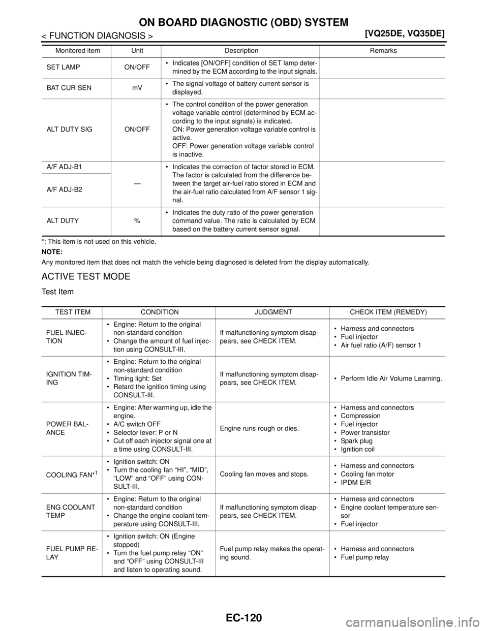
ON BOARD DIAGNOSTIC (OBD) SYSTEM
*: This item is not used on this vehicle.
NOTE:
Any monitored item that does not match the vehicle being diagnosed is deleted from the display automatically.
ACTIVE TEST MODE
Test Item
SET LAMP ON/OFF Indicates [ON/OFF] condition of SET lamp deter-
mined by the ECM according to the input signals.
BAT CUR SEN mV The signal voltage of battery current sensor is
displayed.
ALT DUTY SIG ON/OFF The control condition of the power generation
voltage variable control (determined by ECM ac-
cording to the input signals) is indicated.
ON: Power generation voltage variable control is
active.
OFF: Power generation voltage variable control
is inactive.
A/F ADJ-B1
— Indicates the correction of factor stored in ECM.
The factor is calculated from the difference be-
tween the target air-fuel ratio stored in ECM and
the air-fuel ratio calculated from A/F sensor 1 sig-
nal. A/F ADJ-B2
ALT DUTY % Indicates the duty ratio of the power generation
command value. The ratio is calculated by ECM
based on the battery current sensor signal. Monitored item Unit Description Remarks
TEST ITEM CONDITION JUDGMENT CHECK ITEM (REMEDY)
FUEL INJEC-
TION Engine: Return to the original
non-standard condition
Change the amount of fuel injec-
tion using CONSULT-III.If malfunctioning symptom disap-
pears, see CHECK ITEM. Harness and connectors
Fuel injector
Air fuel ratio (A/F) sensor 1
IGNITION TIM-
ING Engine: Return to the original
non-standard condition
Timing light: Set
Retard the ignition timing using
CONSULT-III.If malfunctioning symptom disap-
pears, see CHECK ITEM. Perform Idle Air Volume Learning.
POWER BAL-
ANCE Engine: After warming up, idle the
engine.
A/C switch OFF
Selector lever: P or N
Cut off each injector signal one at
a time using CONSULT-III.Engine runs rough or dies. Harness and connectors
Compression
Fuel injector
Power transistor
Spark plug
Ignition coil
COOLING FAN*
1
Ignition switch: ON
Turn the cooling fan “HI”, “MID”,
“LOW” and “OFF” using CON-
SULT-III.Cooling fan moves and stops. Harness and connectors
Cooling fan motor
IPDM E/R
ENG COOLANT
TEMP Engine: Return to the original
non-standard condition
Change the engine coolant tem-
perature using CONSULT-III.If malfunctioning symptom disap-
pears, see CHECK ITEM. Harness and connectors
Engine coolant temperature sen-
sor
Fuel injector
FUEL PUMP RE-
LAY Ignition switch: ON (Engine
stopped)
Turn the fuel pump relay “ON”
and “OFF” using CONSULT-III
and listen to operating sound.Fuel pump relay makes the operat-
ing sound. Harness and connectors
Fuel pump relay
Page 1582 of 5121
ON BOARD DIAGNOSTIC (OBD) SYSTEM
EC-121
< FUNCTION DIAGNOSIS >[VQ25DE, VQ35DE]
C
D
E
F
G
H
I
J
K
L
MA
EC
N
P O
*1: Leaving cooling fan OFF with CONSULT-III while engine is running may cause the engine to overheat.
*2: This item is not used on this vehicle.
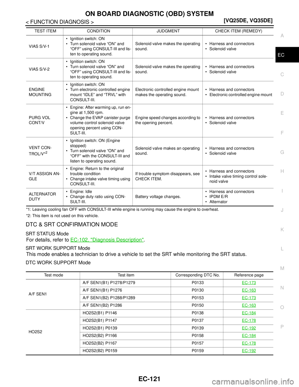
DTC & SRT CONFIRMATION MODE
SRT STATUS Mode
For details, refer to EC-102, "Diagnosis Description".
SRT WORK SUPPORT Mode
This mode enables a technician to drive a vehicle to set the SRT while monitoring the SRT status.
DTC WORK SUPPORT Mode
VIAS S/V-1 Ignition switch: ON
Turn solenoid valve “ON” and
“OFF” using CONSULT-III and lis-
ten to operating sound.Solenoid valve makes the operating
sound. Harness and connectors
Solenoid valve
VIAS S/V-2 Ignition switch: ON
Turn solenoid valve “ON” and
“OFF” using CONSULT-III and lis-
ten to operating sound.Solenoid valve makes the operating
sound. Harness and connectors
Solenoid valve
ENGINE
MOUNTING Ignition switch: ON
Turn electronic controlled engine
mount “IDLE” and “TRVL” with
CONSULT-III.Electronic controlled engine mount
makes the operating sound. Harness and connectors
Electronic controlled engine mount
PURG VOL
CONT/V Engine: After warming up, run en-
gine at 1,500 rpm.
Change the EVAP canister purge
volume control solenoid valve
opening percent using CON-
SULT-III.Engine speed changes according to
the opening percent. Harness and connectors
Solenoid valve
VENT CON-
TROL/V*
2
Ignition switch: ON (Engine
stopped)
Turn solenoid valve “ON” and
“OFF” with the CONSULT-III and
listen to operating sound.Solenoid valve makes an operating
sound. Harness and connectors
Solenoid valve
V/T ASSIGN AN-
GLE Engine: Return to the original
trouble condition
Change intake valve timing using
CONSULT-III.If trouble symptom disappears, see
CHECK ITEM. Harness and connectors
Intake valve timing control sole-
noid valve
ALTERNATOR
DUTY Engine: Idle
Change duty ratio using CON-
SULT-III.Battery voltage changes. Harness and connectors
IPDM E/R
Alternator TEST ITEM CONDITION JUDGMENT CHECK ITEM (REMEDY)
Test mode Test item Corresponding DTC No. Reference page
A/F SEN1A/F SEN1(B1) P1278/P1279 P0133EC-173
A/F SEN1(B1) P1276 P0130EC-163
A/F SEN1(B2) P1288/P1289 P0153EC-173
A/F SEN1(B2) P1286 P0150EC-163
HO2S2HO2S2(B1) P1146 P0138EC-184
HO2S2(B1) P1147 P0137EC-178
HO2S2(B1) P0139 P0139EC-192
HO2S2(B2) P1166 P0158EC-184
HO2S2(B2) P1167 P0157EC-178
HO2S2(B2) P0159 P0159EC-192
Page 1583 of 5121
EC-122
< FUNCTION DIAGNOSIS >[VQ25DE, VQ35DE]
ON BOARD DIAGNOSTIC (OBD) SYSTEM
Diagnosis Tool Function
INFOID:0000000003856504
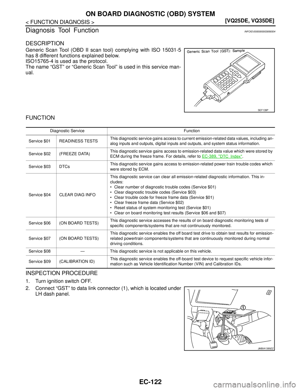
DESCRIPTION
Generic Scan Tool (OBD II scan tool) complying with ISO 15031-5
has 8 different functions explained below.
ISO15765-4 is used as the protocol.
The name “GST” or “Generic Scan Tool” is used in this service man-
ual.
FUNCTION
INSPECTION PROCEDURE
1. Turn ignition switch OFF.
2. Connect “GST” to data link connector (1), which is located under
LH dash panel.
SEF139P
Diagnostic Service Function
Service $01 READINESS TESTSThis diagnostic service gains access to current emission-related data values, including an-
alog inputs and outputs, digital inputs and outputs, and system status information.
Service $02 (FREEZE DATA)This diagnostic service gains access to emission-related data value which were stored by
ECM during the freeze frame. For details, refer to EC-389, "
DTCIndex".
Service $03 DTCsThis diagnostic service gains access to emission-related power train trouble codes which
were stored by ECM.
Service $04 CLEAR DIAG INFOThis diagnostic service can clear all emission-related diagnostic information. This in-
cludes:
Clear number of diagnostic trouble codes (Service $01)
Clear diagnostic trouble codes (Service $03)
Clear trouble code for freeze frame data (Service $01)
Clear freeze frame data (Service $02)
Reset status of system monitoring test (Service $01)
Clear on board monitoring test results (Service $06 and $07)
Service $06 (ON BOARD TESTS)This diagnostic service accesses the results of on board diagnostic monitoring tests of
specific components/systems that are not continuously monitored.
Service $07 (ON BOARD TESTS)This diagnostic service enables the off board test drive to obtain test results for emission-
related powertrain components/systems that are continuously monitored during normal
driving conditions.
Service $08 — This diagnostic service is not applicable on this vehicle.
Service $09 (CALIBRATION ID)This diagnostic service enables the off-board test device to request specific vehicle infor-
mation such as Vehicle Identification Number (VIN) and Calibration IDs.
JMBIA1389ZZ
Page 1584 of 5121
ON BOARD DIAGNOSTIC (OBD) SYSTEM
EC-123
< FUNCTION DIAGNOSIS >[VQ25DE, VQ35DE]
C
D
E
F
G
H
I
J
K
L
MA
EC
N
P O
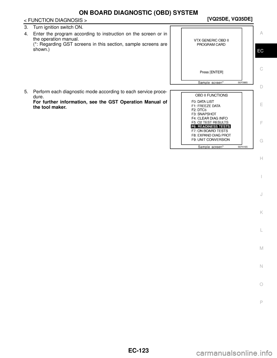
3. Turn ignition switch ON.
4. Enter the program according to instruction on the screen or in
the operation manual.
(*: Regarding GST screens in this section, sample screens are
shown.)
5. Perform each diagnostic mode according to each service proce-
dure.
For further information, see the GST Operation Manual of
the tool maker.
SEF398S
SEF416S
Page 1596 of 5121
U1000, U1001 CAN COMM CIRCUIT
EC-135
< COMPONENT DIAGNOSIS >[VQ25DE, VQ35DE]
C
D
E
F
G
H
I
J
K
L
MA
EC
N
P O
U1000, U1001 CAN COMM CIRCUIT
DescriptionINFOID:0000000003856509
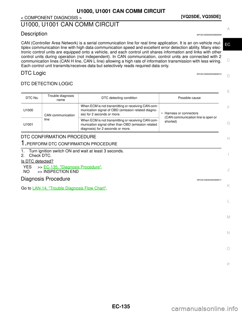
CAN (Controller Area Network) is a serial communication line for real time application. It is an on-vehicle mul-
tiplex communication line with high data communication speed and excellent error detection ability. Many elec-
tronic control units are equipped onto a vehicle, and each control unit shares information and links with other
control units during operation (not independent). In CAN communication, control units are connected with 2
communication lines (CAN H line, CAN L line) allowing a high rate of information transmission with less wiring.
Each control unit transmits/receives data but selectively reads required data only.
DTC LogicINFOID:0000000003856510
DTC DETECTION LOGIC
DTC CONFIRMATION PROCEDURE
1.PERFORM DTC CONFIRMATION PROCEDURE
1. Turn ignition switch ON and wait at least 3 seconds.
2. Check DTC.
Is DTC detected?
YES >>EC-135, "Diagnosis Procedure".
NO >> INSPECTION END
Diagnosis ProcedureINFOID:0000000003856511
Go to LAN-14, "Trouble Diagnosis Flow Chart".
DTC No.Trouble diagnosis
nameDTC detecting condition Possible cause
U1000
CAN communication
lineWhen ECM is not transmitting or receiving CAN com-
munication signal of OBD (emission related diagno-
sis) for 2 seconds or more. Harness or connectors
(CAN communication line is open or
shorted)
U1001When ECM is not transmitting or receiving CAN com-
munication signal other than OBD (emission related
diagnosis) for 2 seconds or more.
Page 1855 of 5121
EC-394
< ECU DIAGNOSIS >[VQ25DE, VQ35DE]
ECM
Sea level
Flat road
Ambient air temperature: 20 - 30°C (68 - 86°F)
Diagnosis is performed as quickly as possible under normal conditions.
Under different conditions [For example: ambient air temperature other than 20 - 30°C (68 - 86°F)], diagno-
sis may also be performed.
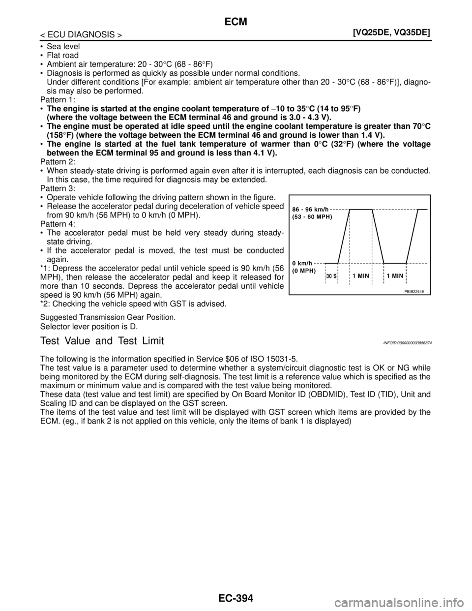
Pattern 1:
The engine is started at the engine coolant temperature of −10 to 35°C (14 to 95°F)
(where the voltage between the ECM terminal 46 and ground is 3.0 - 4.3 V).
The engine must be operated at idle speed until the engine coolant temperature is greater than 70°C
(158°F) (where the voltage between the ECM terminal 46 and ground is lower than 1.4 V).
The engine is started at the fuel tank temperature of warmer than 0°C (32°F) (where the voltage
between the ECM terminal 95 and ground is less than 4.1 V).
Pattern 2:
When steady-state driving is performed again even after it is interrupted, each diagnosis can be conducted.
In this case, the time required for diagnosis may be extended.
Pattern 3:
Operate vehicle following the driving pattern shown in the figure.
Release the accelerator pedal during deceleration of vehicle speed
from 90 km/h (56 MPH) to 0 km/h (0 MPH).
Pattern 4:
The accelerator pedal must be held very steady during steady-
state driving.
If the accelerator pedal is moved, the test must be conducted
again.
*1: Depress the accelerator pedal until vehicle speed is 90 km/h (56
MPH), then release the accelerator pedal and keep it released for
more than 10 seconds. Depress the accelerator pedal until vehicle
speed is 90 km/h (56 MPH) again.
*2: Checking the vehicle speed with GST is advised.
Suggested Transmission Gear Position.
Selector lever position is D.
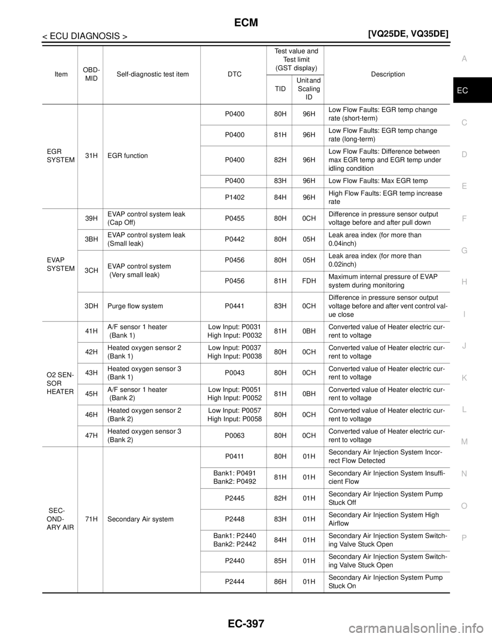
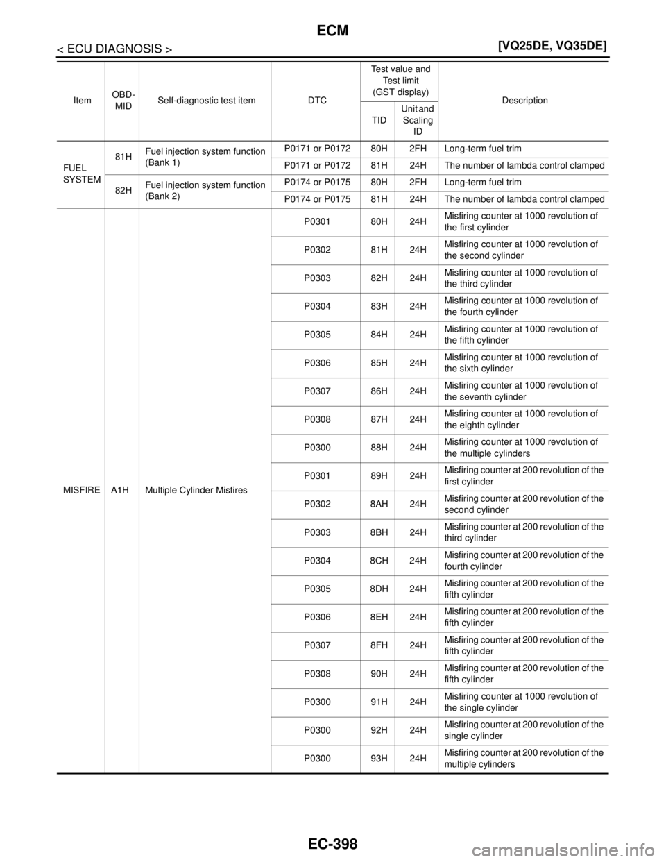
Test Value and Test LimitINFOID:0000000003856874
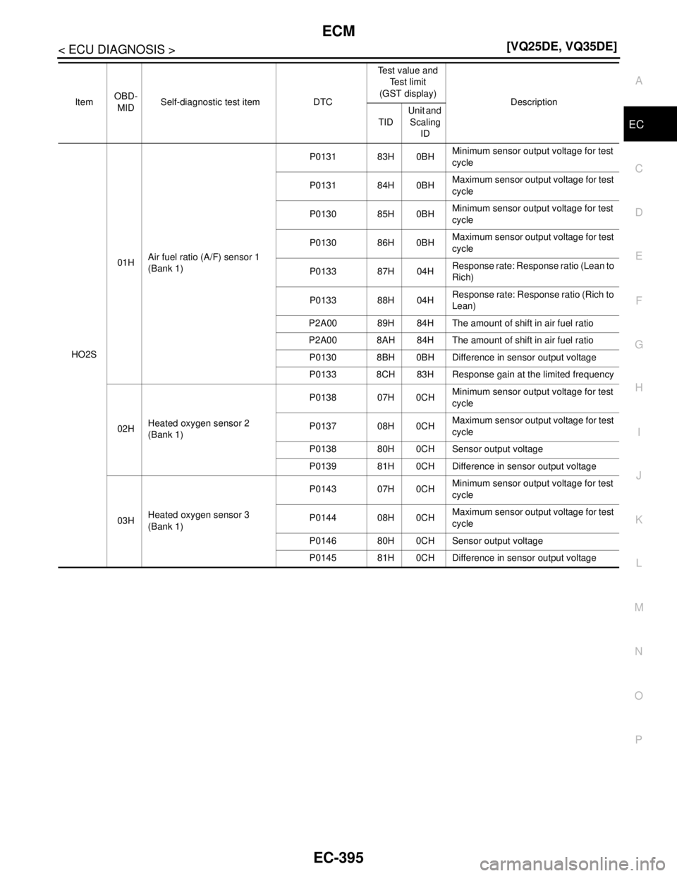
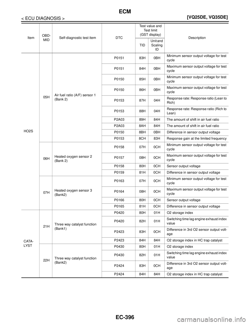
The following is the information specified in Service $06 of ISO 15031-5.
The test value is a parameter used to determine whether a system/circuit diagnostic test is OK or NG while
being monitored by the ECM during self-diagnosis. The test limit is a reference value which is specified as the
maximum or minimum value and is compared with the test value being monitored.
These data (test value and test limit) are specified by On Board Monitor ID (OBDMID), Test ID (TID), Unit and
Scaling ID and can be displayed on the GST screen.
The items of the test value and test limit will be displayed with GST screen which items are provided by the
ECM. (eg., if bank 2 is not applied on this vehicle, only the items of bank 1 is displayed)
PBIB2244E
Page 1856 of 5121
ECM
EC-395
< ECU DIAGNOSIS >[VQ25DE, VQ35DE]
C
D
E
F
G
H
I
J
K
L
MA
EC
N
P O
ItemOBD-
MIDSelf-diagnostic test item DTCTest value and
Te s t l i m i t
(GST display)
Description
TIDUnit and
Scaling
ID
HO2S01HAir fuel ratio (A/F) sensor 1
(Bank 1)P0131 83H 0BHMinimum sensor output voltage for test
cycle
P0131 84H 0BHMaximum sensor output voltage for test
cycle
P0130 85H 0BHMinimum sensor output voltage for test
cycle
P0130 86H 0BHMaximum sensor output voltage for test
cycle
P0133 87H 04HResponse rate: Response ratio (Lean to
Rich)
P0133 88H 04HResponse rate: Response ratio (Rich to
Lean)
P2A00 89H 84H The amount of shift in air fuel ratio
P2A00 8AH 84H The amount of shift in air fuel ratio
P0130 8BH 0BH Difference in sensor output voltage
P0133 8CH 83H Response gain at the limited frequency
02HHeated oxygen sensor 2
(Bank 1)P0138 07H 0CHMinimum sensor output voltage for test
cycle
P0137 08H 0CHMaximum sensor output voltage for test
cycle
P0138 80H 0CH Sensor output voltage
P0139 81H 0CH Difference in sensor output voltage
03HHeated oxygen sensor 3
(Bank 1)P0143 07H 0CHMinimum sensor output voltage for test
cycle
P0144 08H 0CHMaximum sensor output voltage for test
cycle
P0146 80H 0CH Sensor output voltage
P0145 81H 0CH Difference in sensor output voltage
Page 1857 of 5121
EC-396
< ECU DIAGNOSIS >[VQ25DE, VQ35DE]
ECM
HO2S05HAir fuel ratio (A/F) sensor 1
(Bank 2)P0151 83H 0BHMinimum sensor output voltage for test
cycle
P0151 84H 0BHMaximum sensor output voltage for test
cycle
P0150 85H 0BHMinimum sensor output voltage for test
cycle
P0150 86H 0BHMaximum sensor output voltage for test
cycle
P0153 87H 04HResponse rate: Response ratio (Lean to
Rich)
P0153 88H 04HResponse rate: Response ratio (Rich to
Lean)
P2A03 89H 84H The amount of shift in air fuel ratio
P2A03 8AH 84H The amount of shift in air fuel ratio
P0150 8BH 0BH Difference in sensor output voltage
P0153 8CH 83H Response gain at the limited frequency
06HHeated oxygen sensor 2
(Bank 2)P0158 07H 0CHMinimum sensor output voltage for test
cycle
P0157 08H 0CHMaximum sensor output voltage for test
cycle
P0158 80H 0CH Sensor output voltage
P0159 81H 0CH Difference in sensor output voltage
07HHeated oxygen sensor 3
(Bank2)P0163 07H 0CHMinimum sensor output voltage for test
cycle
P0164 08H 0CHMaximum sensor output voltage for test
cycle
P0166 80H 0CH Sensor output voltage
P0165 81H 0CH Difference in sensor output voltage
CATA-
LYST21HThree way catalyst function
(Bank1)P0420 80H 01H O2 storage index
P0420 82H 01HSwitching time lag engine exhaust index
value
P2423 83H 0CHDifference in 3rd O2 sensor output volt-
age
P2423 84H 84H O2 storage index in HC trap catalyst
22HThree way catalyst function
(Bank2)P0430 80H 01H O2 storage index
P0430 82H 01HSwitching time lag engine exhaust index
value
P2424 83H 0CHDifference in 3rd O2 sensor output volt-
age
P2424 84H 84H O2 storage index in HC trap catalyst ItemOBD-
MIDSelf-diagnostic test item DTCTest value and
Te s t l i m i t
(GST display)
Description
TIDUnit and
Scaling
ID
Page 1858 of 5121
ECM
EC-397
< ECU DIAGNOSIS >[VQ25DE, VQ35DE]
C
D
E
F
G
H
I
J
K
L
MA
EC
N
P O
EGR
SYSTEM31H EGR functionP0400 80H 96HLow Flow Faults: EGR temp change
rate (short-term)
P0400 81H 96HLow Flow Faults: EGR temp change
rate (long-term)
P0400 82H 96HLow Flow Faults: Difference between
max EGR temp and EGR temp under
idling condition
P0400 83H 96H Low Flow Faults: Max EGR temp
P1402 84H 96HHigh Flow Faults: EGR temp increase
rate
EVAP
SYSTEM39HEVAP control system leak
(Cap Off)P0455 80H 0CHDifference in pressure sensor output
voltage before and after pull down
3BHEVAP control system leak
(Small leak)P0442 80H 05HLeak area index (for more than
0.04inch)
3CHEVAP control system
(Very small leak)P0456 80H 05HLeak area index (for more than
0.02inch)
P0456 81H FDHMaximum internal pressure of EVAP
system during monitoring
3DH Purge flow system P0441 83H 0CHDifference in pressure sensor output
voltage before and after vent control val-
ue close
O2 SEN-
SOR
HEATER41HA/F sensor 1 heater
(Bank 1)Low Input: P0031
High Input: P003281H 0BHConverted value of Heater electric cur-
rent to voltage
42HHeated oxygen sensor 2
(Bank 1)Low Input: P0037
High Input: P003880H 0CHConverted value of Heater electric cur-
rent to voltage
43HHeated oxygen sensor 3
(Bank 1)P0043 80H 0CHConverted value of Heater electric cur-
rent to voltage
45HA/F sensor 1 heater
(Bank 2)Low Input: P0051
High Input: P005281H 0BHConverted value of Heater electric cur-
rent to voltage
46HHeated oxygen sensor 2
(Bank 2)Low Input: P0057
High Input: P005880H 0CHConverted value of Heater electric cur-
rent to voltage
47HHeated oxygen sensor 3
(Bank 2)P0063 80H 0CHConverted value of Heater electric cur-
rent to voltage
SEC-
OND-
ARY AIR71H Secondary Air systemP0411 80H 01HSecondary Air Injection System Incor-
rect Flow Detected
Bank1: P0491
Bank2: P049281H 01HSecondary Air Injection System Insuffi-
cient Flow
P2445 82H 01HSecondary Air Injection System Pump
Stu c k O ff
P2448 83H 01HSecondary Air Injection System High
Airflow
Bank1: P2440
Bank2: P244284H 01HSecondary Air Injection System Switch-
ing Valve Stuck Open
P2440 85H 01HSecondary Air Injection System Switch-
ing Valve Stuck Open
P2444 86H 01HSecondary Air Injection System Pump
Stu c k O n ItemOBD-
MIDSelf-diagnostic test item DTCTest value and
Te s t l i m i t
(GST display)
Description
TIDUnit and
Scaling
ID
Page 1859 of 5121
EC-398
< ECU DIAGNOSIS >[VQ25DE, VQ35DE]
ECM
FUEL
SYSTEM81HFuel injection system function
(Bank 1)P0171 or P0172 80H 2FH Long-term fuel trim
P0171 or P0172 81H 24H The number of lambda control clamped
82HFuel injection system function
(Bank 2)P0174 or P0175 80H 2FH Long-term fuel trim
P0174 or P0175 81H 24H The number of lambda control clamped
MISFIRE A1H Multiple Cylinder MisfiresP0301 80H 24HMisfiring counter at 1000 revolution of
the first cylinder
P0302 81H 24HMisfiring counter at 1000 revolution of
the second cylinder
P0303 82H 24HMisfiring counter at 1000 revolution of
the third cylinder
P0304 83H 24HMisfiring counter at 1000 revolution of
the fourth cylinder
P0305 84H 24HMisfiring counter at 1000 revolution of
the fifth cylinder
P0306 85H 24HMisfiring counter at 1000 revolution of
the sixth cylinder
P0307 86H 24HMisfiring counter at 1000 revolution of
the seventh cylinder
P0308 87H 24HMisfiring counter at 1000 revolution of
the eighth cylinder
P0300 88H 24HMisfiring counter at 1000 revolution of
the multiple cylinders
P0301 89H 24HMisfiring counter at 200 revolution of the
first cylinder
P0302 8AH 24HMisfiring counter at 200 revolution of the
second cylinder
P0303 8BH 24HMisfiring counter at 200 revolution of the
third cylinder
P0304 8CH 24HMisfiring counter at 200 revolution of the
fourth cylinder
P0305 8DH 24HMisfiring counter at 200 revolution of the
fifth cylinder
P0306 8EH 24HMisfiring counter at 200 revolution of the
fifth cylinder
P0307 8FH 24HMisfiring counter at 200 revolution of the
fifth cylinder
P0308 90H 24HMisfiring counter at 200 revolution of the
fifth cylinder
P0300 91H 24HMisfiring counter at 1000 revolution of
the single cylinder
P0300 92H 24HMisfiring counter at 200 revolution of the
single cylinder
P0300 93H 24HMisfiring counter at 200 revolution of the
multiple cylinders ItemOBD-
MIDSelf-diagnostic test item DTCTest value and
Te s t l i m i t
(GST display)
Description
TIDUnit and
Scaling
ID