brake rotor NISSAN TEANA 2008 Owner's Manual
[x] Cancel search | Manufacturer: NISSAN, Model Year: 2008, Model line: TEANA, Model: NISSAN TEANA 2008Pages: 5121, PDF Size: 69.03 MB
Page 2440 of 5121
FAX-12
< ON-VEHICLE REPAIR >
FRONT DRIVE SHAFT BOOT
WHEEL SIDE
WHEEL SIDE : Removal and InstallationINFOID:0000000003811080
REMOVAL
1. Remove tires.
2. Remove wheel sensor and sensor harness. Refer to BRC-57, "
FRONT WHEEL SENSOR : Exploded
View" (without VDC), BRC-151, "FRONT WHEEL SENSOR : Exploded View" (with VDC).
3. Remove lock plate of brake hose from strut assembly. Refer to BR-19, "
FRONT : Exploded View".
4. Remove caliper assembly. Hang caliper assembly not to interfere with work. Refer to BR-34, "
BRAKE
CALIPER ASSEMBLY : Exploded View".
5. Remove disc rotor. Refer to BR-35, "
BRAKE CALIPER ASSEMBLY : Removal and Installation".
6. Remove cotter pin, and then loosen wheel hub lock nut. Refer to FA X - 8 , "
Exploded View".
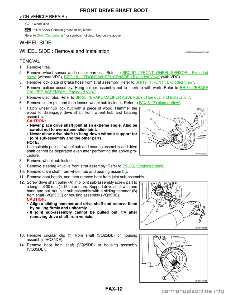
7. Patch wheel hub lock nut with a piece of wood. Hammer the
wood to disengage drive shaft from wheel hub and bearing
assembly.
CAUTION:
Never place drive shaft joint at an extreme angle. Also be
careful not to overextend slide joint.
Never allow drive shaft to hang down without support for
joint sub-assembly and the other parts.
NOTE:
Use suitable puller, if wheel hub and bearing assembly and drive
shaft cannot be separated even after performing the above pro-
cedure.
8. Remove wheel hub lock nut.
9. Remove steering knuckle from strut assembly. Refer to FSU-9, "
Exploded View".
10. Remove drive shaft from wheel hub and bearing assembly.
11. Remove boot bands, and then remove boot from joint sub-assembly.
12. Screw drive shaft puller (A) into joint sub-assembly screw part to
a length of 30 mm (1.18 in) or more. Support drive shaft with one
hand and pull out joint sub-assembly with a sliding hammer (B)
from shaft (VQ25DE) or housing assembly (VQ35DE).
CAUTION:
Align a sliding hammer and drive shaft and remove them
by pulling firmly and uniformly.
If joint sub-assembly cannot be pulled out, try after
removing drive shaft from vehicle.
13. Remove circular clip (1) from shaft (VQ25DE) or housing
assembly (VQ35DE).
14. Remove boot from shaft (VQ25DE) or housing assembly
(VQ35DE).
: Wheel side
: Fill NISSAN Genuine grease or equivalent.
Refer to GI-4, "
Components" for symbols not described on the above.
JPDIG0070ZZ
JPDIF0022ZZ
JPDIF0007ZZ
Page 2442 of 5121
FAX-14
< ON-VEHICLE REPAIR >
FRONT DRIVE SHAFT BOOT
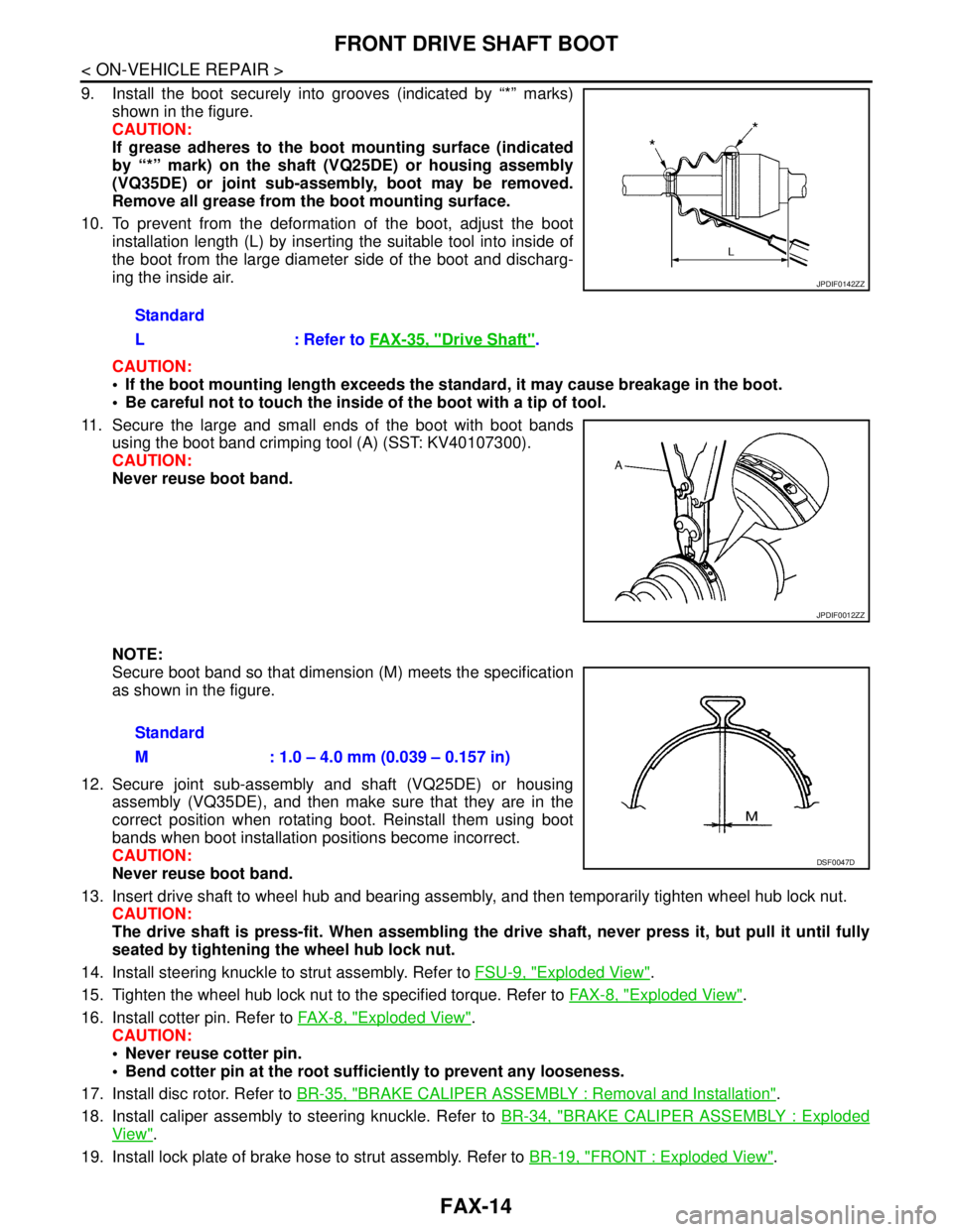
9. Install the boot securely into grooves (indicated by “*” marks)
shown in the figure.
CAUTION:
If grease adheres to the boot mounting surface (indicated
by “*” mark) on the shaft (VQ25DE) or housing assembly
(VQ35DE) or joint sub-assembly, boot may be removed.
Remove all grease from the boot mounting surface.
10. To prevent from the deformation of the boot, adjust the boot
installation length (L) by inserting the suitable tool into inside of
the boot from the large diameter side of the boot and discharg-
ing the inside air.
CAUTION:
If the boot mounting length exceeds the standard, it may cause breakage in the boot.
Be careful not to touch the inside of the boot with a tip of tool.
11. Secure the large and small ends of the boot with boot bands
using the boot band crimping tool (A) (SST: KV40107300).
CAUTION:
Never reuse boot band.
NOTE:
Secure boot band so that dimension (M) meets the specification
as shown in the figure.
12. Secure joint sub-assembly and shaft (VQ25DE) or housing
assembly (VQ35DE), and then make sure that they are in the
correct position when rotating boot. Reinstall them using boot
bands when boot installation positions become incorrect.
CAUTION:
Never reuse boot band.
13. Insert drive shaft to wheel hub and bearing assembly, and then temporarily tighten wheel hub lock nut.
CAUTION:
The drive shaft is press-fit. When assembling the drive shaft, never press it, but pull it until fully
seated by tightening the wheel hub lock nut.
14. Install steering knuckle to strut assembly. Refer to FSU-9, "
Exploded View".
15. Tighten the wheel hub lock nut to the specified torque. Refer to FA X - 8 , "
Exploded View".
16. Install cotter pin. Refer to FA X - 8 , "
Exploded View".
CAUTION:
Never reuse cotter pin.
Bend cotter pin at the root sufficiently to prevent any looseness.
17. Install disc rotor. Refer to BR-35, "
BRAKE CALIPER ASSEMBLY : Removal and Installation".
18. Install caliper assembly to steering knuckle. Refer to BR-34, "
BRAKE CALIPER ASSEMBLY : Exploded
View".
19. Install lock plate of brake hose to strut assembly. Refer to BR-19, "
FRONT : Exploded View". Standard
L : Refer to FAX-35, "
Drive Shaft".
JPDIF0142ZZ
JPDIF0012ZZ
Standard
M : 1.0 – 4.0 mm (0.039 – 0.157 in)
DSF0047D
Page 2446 of 5121
FAX-18
< ON-VEHICLE REPAIR >
FRONT DRIVE SHAFT
LEFT SIDE
LEFT SIDE : Removal and InstallationINFOID:0000000003811084
REMOVAL
1. Remove tires.
2. Remove wheel sensor and sensor harness. Refer to BRC-57, "
FRONT WHEEL SENSOR : Exploded
View" (without VDC), BRC-151, "FRONT WHEEL SENSOR : Exploded View" (with VDC).
3. Remove lock plate of brake hose from strut assembly. Refer to BR-19, "
FRONT : Exploded View".
4. Remove caliper assembly. Hang caliper assembly not to interfere with work. Refer to BR-34, "
BRAKE
CALIPER ASSEMBLY : Exploded View".
5. Remove disc rotor. Refer to BR-35, "
BRAKE CALIPER ASSEMBLY : Removal and Installation".
6. Remove cotter pin, and then loosen wheel hub lock nut. Refer to FA X - 8 , "
Exploded View".
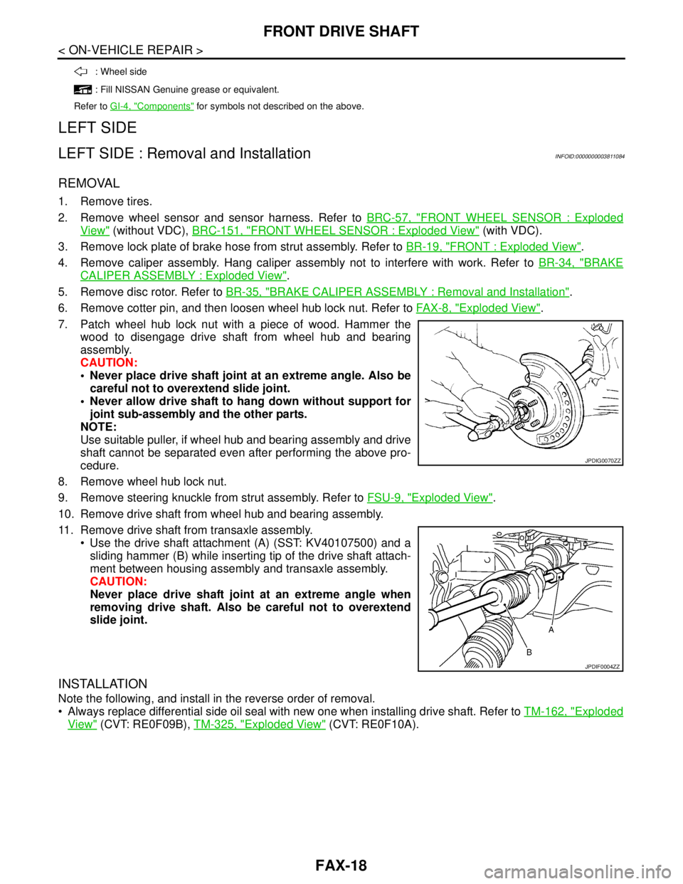
7. Patch wheel hub lock nut with a piece of wood. Hammer the
wood to disengage drive shaft from wheel hub and bearing
assembly.
CAUTION:
Never place drive shaft joint at an extreme angle. Also be
careful not to overextend slide joint.
Never allow drive shaft to hang down without support for
joint sub-assembly and the other parts.
NOTE:
Use suitable puller, if wheel hub and bearing assembly and drive
shaft cannot be separated even after performing the above pro-
cedure.
8. Remove wheel hub lock nut.
9. Remove steering knuckle from strut assembly. Refer to FSU-9, "
Exploded View".
10. Remove drive shaft from wheel hub and bearing assembly.
11. Remove drive shaft from transaxle assembly.
Use the drive shaft attachment (A) (SST: KV40107500) and a
sliding hammer (B) while inserting tip of the drive shaft attach-
ment between housing assembly and transaxle assembly.
CAUTION:
Never place drive shaft joint at an extreme angle when
removing drive shaft. Also be careful not to overextend
slide joint.
INSTALLATION
Note the following, and install in the reverse order of removal.
Always replace differential side oil seal with new one when installing drive shaft. Refer to TM-162, "
Exploded
View" (CVT: RE0F09B), TM-325, "Exploded View" (CVT: RE0F10A).
: Wheel side
: Fill NISSAN Genuine grease or equivalent.
Refer to GI-4, "
Components" for symbols not described on the above.
JPDIG0070ZZ
JPDIF0004ZZ
Page 2447 of 5121
FRONT DRIVE SHAFT
FAX-19
< ON-VEHICLE REPAIR >
C
E
F
G
H
I
J
K
L
MA
B
FA X
N
O
P
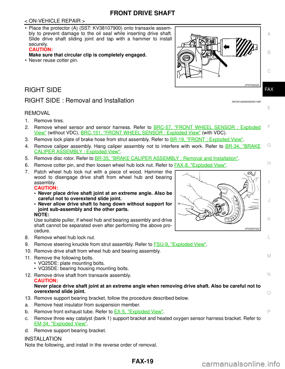
Place the protector (A) (SST: KV38107900) onto transaxle assem-
bly to prevent damage to the oil seal while inserting drive shaft.
Slide drive shaft sliding joint and tap with a hammer to install
securely.
CAUTION:
Make sure that circular clip is completely engaged.
Never reuse cotter pin.
RIGHT SIDE
RIGHT SIDE : Removal and InstallationINFOID:0000000003811085
REMOVAL
1. Remove tires.
2. Remove wheel sensor and sensor harness. Refer to BRC-57, "
FRONT WHEEL SENSOR : Exploded
View" (without VDC), BRC-151, "FRONT WHEEL SENSOR : Exploded View" (with VDC).
3. Remove lock plate of brake hose from strut assembly. Refer to BR-19, "
FRONT : Exploded View".
4. Remove caliper assembly. Hang caliper assembly not to interfere with work. Refer to BR-34, "
BRAKE
CALIPER ASSEMBLY : Exploded View".
5. Remove disc rotor. Refer to BR-35, "
BRAKE CALIPER ASSEMBLY : Removal and Installation".
6. Remove cotter pin, and then loosen wheel hub lock nut. Refer to FA X - 8 , "
Exploded View".
7. Patch wheel hub lock nut with a piece of wood. Hammer the
wood to disengage drive shaft from wheel hub and bearing
assembly.
CAUTION:
Never place drive shaft joint at an extreme angle. Also be
careful not to overextend slide joint.
Never allow drive shaft to hang down without support for
joint sub-assembly and the other parts.
NOTE:
Use suitable puller, if wheel hub and bearing assembly and drive
shaft cannot be separated even after performing the above pro-
cedure.
8. Remove wheel hub lock nut.
9. Remove steering knuckle from strut assembly. Refer to FSU-9, "
Exploded View".
10. Remove drive shaft from wheel hub and bearing assembly.
11. Remove the following bolts.
VQ25DE: plate mounting bolts.
VQ35DE: bearing housing mounting bolts.
12. Remove drive shaft from transaxle assembly.
CAUTION:
Never place drive shaft joint at an extreme angle when removing drive shaft. Also be careful not to
overextend slide joint.
13. Remove support bearing bracket, follow the procedure described below.
a. Remove heat insulator from suspension member.
b. Remove front exhaust tube. Refer to EX-5, "
Exploded View".
c. Remove three way catalyst (bank 1) support bracket and heated oxygen sensor harness bracket. Refer to
EM-34, "
Exploded View".
d. Remove support bearing bracket.
INSTALLATION
Note the following, and install in the reverse order of removal.
JPDIF0023ZZ
JPDIG0070ZZ
Page 3195 of 5121
PERIODIC MAINTENANCE
MA-7
< ON-VEHICLE MAINTENANCE >
C
D
E
F
G
H
I
J
K
L
MB
MAN
OA
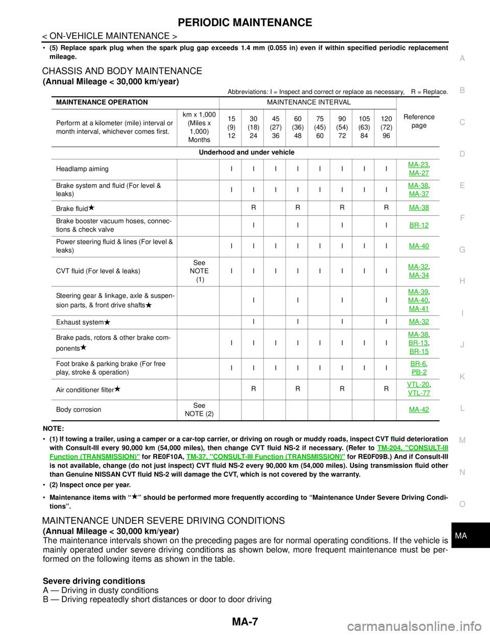
(5) Replace spark plug when the spark plug gap exceeds 1.4 mm (0.055 in) even if within specified periodic replacement
mileage.
CHASSIS AND BODY MAINTENANCE
(Annual Mileage < 30,000 km/year)
Abbreviations: I = Inspect and correct or replace as necessary, R = Replace.
NOTE:
(1) If towing a trailer, using a camper or a car-top carrier, or driving on rough or muddy roads, inspect CVT fluid deterioration
with Consult-III every 90,000 km (54,000 miles), then change CVT fluid NS-2 if necessary. (Refer to TM-204, "
CONSULT-III
Function (TRANSMISSION)" for RE0F10A, TM-37, "CONSULT-III Function (TRANSMISSION)" for RE0F09B.) And if Consult-III
is not available, change (do not just inspect) CVT fluid NS-2 every 90,000 km (54,000 miles). Using transmission fluid other
than Genuine NISSAN CVT fluid NS-2 will damage the CVT, which is not covered by the warranty.
(2) Inspect once per year.
Maintenance items with “ ” should be performed more frequently according to “Maintenance Under Severe Driving Condi-
tions”.
MAINTENANCE UNDER SEVERE DRIVING CONDITIONS
(Annual Mileage < 30,000 km/year)
The maintenance intervals shown on the preceding pages are for normal operating conditions. If the vehicle is
mainly operated under severe driving conditions as shown below, more frequent maintenance must be per-
formed on the following items as shown in the table.
Severe driving conditions
A — Driving in dusty conditions
B — Driving repeatedly short distances or door to door driving
MAINTENANCE OPERATIONMAINTENANCE INTERVAL
Reference
page Perform at a kilometer (mile) interval or
month interval, whichever comes first.km x 1,000
(Miles x
1,000)
Months15
(9)
1230
(18)
2445
(27)
3660
(36)
4875
(45)
6090
(54)
72105
(63)
84120
(72)
96
Underhood and under vehicle
Headlamp aiming IIIIIIIIMA-23
,
MA-27
Brake system and fluid (For level &
leaks)IIIIIIIIMA-38,
MA-37
Brake fluidRRRRMA-38
Brake booster vacuum hoses, connec-
tions & check valveIIIIBR-12
Power steering fluid & lines (For level &
leaks)IIIIIIIIMA-40
CVT fluid (For level & leaks)See
NOTE
(1)IIIIIIIIMA-32,
MA-34
Steering gear & linkage, axle & suspen-
sion parts, & front drive shaftsIIIIMA-39,
MA-40
,
MA-41
Exhaust systemIIIIMA-32
Brake pads, rotors & other brake com-
ponentsIIIIIIIIMA-38,
BR-13
,
BR-15
Foot brake & parking brake (For free
play, stroke & operation)IIIIIIIIBR-6,
PB-2
Air conditioner filterRRRRVTL-20,
VTL-77
Body corrosionSee
NOTE (2)MA-42
Page 3196 of 5121
MA-8
< ON-VEHICLE MAINTENANCE >
PERIODIC MAINTENANCE
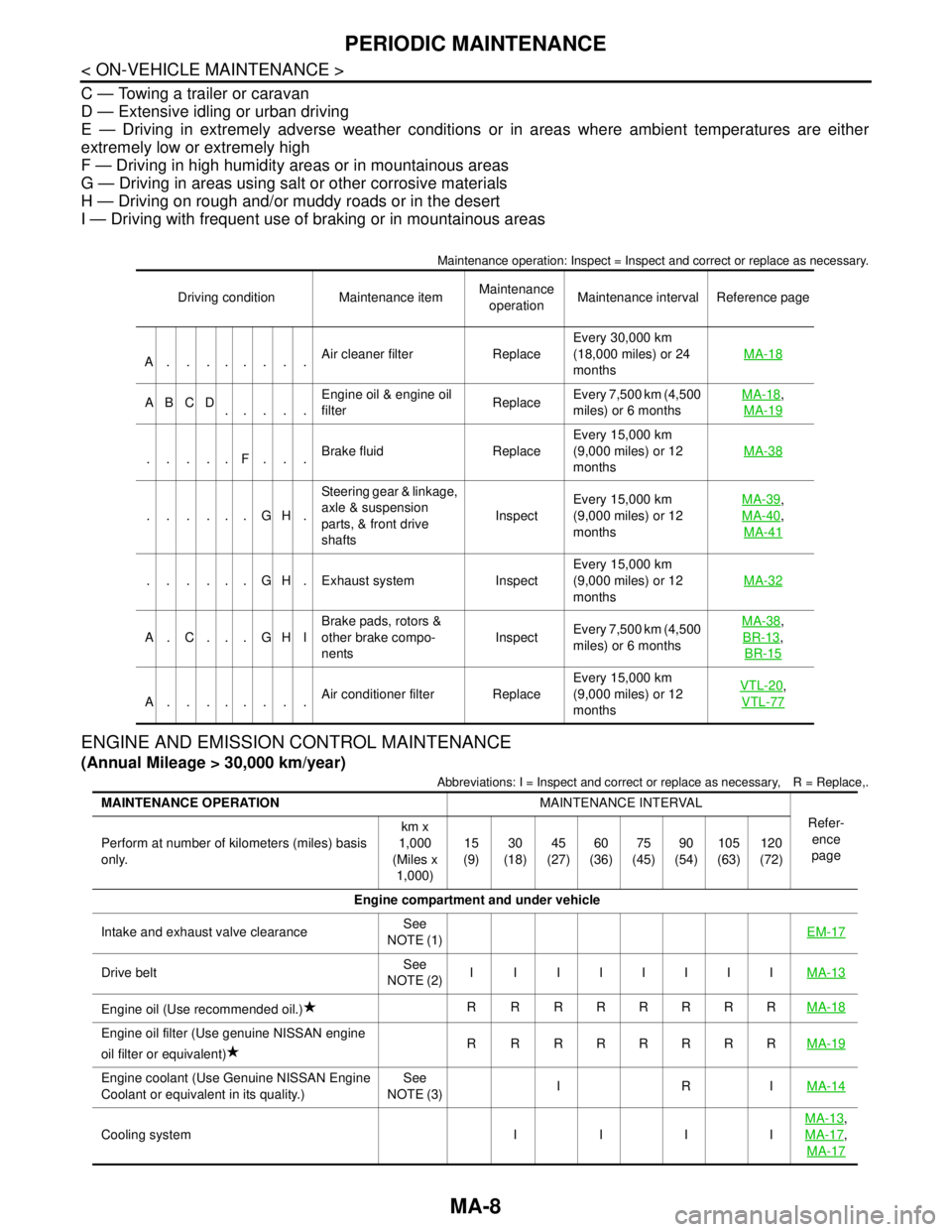
C — Towing a trailer or caravan
D — Extensive idling or urban driving
E — Driving in extremely adverse weather conditions or in areas where ambient temperatures are either
extremely low or extremely high
F — Driving in high humidity areas or in mountainous areas
G — Driving in areas using salt or other corrosive materials
H — Driving on rough and/or muddy roads or in the desert
I — Driving with frequent use of braking or in mountainous areas
Maintenance operation: Inspect = Inspect and correct or replace as necessary.
ENGINE AND EMISSION CONTROL MAINTENANCE
(Annual Mileage > 30,000 km/year)
Abbreviations: I = Inspect and correct or replace as necessary, R = Replace,.
Driving condition Maintenance itemMaintenance
operationMaintenance interval Reference page
A........Air cleaner filter ReplaceEvery 30,000 km
(18,000 miles) or 24
monthsMA-18
ABCD
.....Engine oil & engine oil
filter ReplaceEvery 7,500 km (4,500
miles) or 6 monthsMA-18,
MA-19
.....F...Brake fluid ReplaceEvery 15,000 km
(9,000 miles) or 12
monthsMA-38
......GH.Steering gear & linkage,
axle & suspension
parts, & front drive
shafts InspectEvery 15,000 km
(9,000 miles) or 12
monthsMA-39
,
MA-40
,
MA-41
. . . . . . G H . Exhaust system InspectEvery 15,000 km
(9,000 miles) or 12
monthsMA-32
A. C. . . GHIBrake pads, rotors &
other brake compo-
nentsInspectEvery 7,500 km (4,500
miles) or 6 monthsMA-38
,
BR-13
,
BR-15
A........Air conditioner filter ReplaceEvery 15,000 km
(9,000 miles) or 12
monthsVTL-20
,
VTL-77
MAINTENANCE OPERATIONMAINTENANCE INTERVAL
Refer-
ence
page Perform at number of kilometers (miles) basis
only.km x
1,000
(Miles x
1,000)15
(9)30
(18)45
(27)60
(36)75
(45)90
(54)105
(63)120
(72)
Engine compartment and under vehicle
Intake and exhaust valve clearanceSee
NOTE (1)EM-17
Drive beltSee
NOTE (2)I I IIIIIIMA-13
Engine oil (Use recommended oil.)R RRRRRRRMA-18
Engine oil filter (Use genuine NISSAN engine
oil filter or equivalent)R RRRRRRRMA-19
Engine coolant (Use Genuine NISSAN Engine
Coolant or equivalent in its quality.)See
NOTE (3)IRIMA-14
Cooling system I I I IMA-13
,
MA-17
,
MA-17
Page 3197 of 5121

PERIODIC MAINTENANCE
MA-9
< ON-VEHICLE MAINTENANCE >
C
D
E
F
G
H
I
J
K
L
MB
MAN
OA
NOTE:
Maintenance items with “ ” should be performed more frequently according to “Maintenance Under Severe Driving Condi-
tions”.
(1) Periodic maintenance is not required. However, if valve noise increases, check valve clearance.
(2) Replace the drive belt if found damaged or if the auto belt tensioner reading reaches the maximum limit.
(3) Use Genuine NISSAN Engine Coolant or equivalent in its quality, in order to avoid possible aluminum corrosion within
the engine cooling system caused by the use of non-genuine coolant.
First replace at 90,000 km (54,000 miles), then every 60,000 km (36,000 miles). Perform "I" (Checking the mixture ratio and
correcting the mixture ratio if necessary) at the middle of replacement interval.
(4) Fuel filter is maintenance-free. For service procedures, refer to FL section.
(5) Replace spark plug when the spark plug gap exceeds 1.4 mm (0.055 in) even if within specified periodic replacement
mileage.
CHASSIS AND BODY MAINTENANCE
(Annual Mileage > 30,000 km/year)
Abbreviations: I = Inspect and correct or replace as necessary, R = Replace, L = Lubricate.
Fuel and EVAP vapor lines I IMA-18,
MA-22
Air cleaner filterRRMA-18
Fuel filter (In-tank type)See
NOTE (4)—
Positive crankcase ventilation (PCV) system I I I IMA-21
Spark-plugs (Iridium-tipped type)See
NOTE (5)R R RRRRRRMA-20
MAINTENANCE OPERATIONMAINTENANCE INTERVAL
Refer-
ence
page Perform at number of kilometers (miles) basis
only.km x
1,000
(Miles x
1,000)15
(9)30
(18)45
(27)60
(36)75
(45)90
(54)105
(63)120
(72)
MAINTENANCE OPERATIONMAINTENANCE INTERVAL
Reference
page Perform at number of kilometers (miles)
basis only.km x 1,000
(Miles x
1,000)15
(9)30
(18)45
(27)60
(36)75
(45)90
(54)105
(63)120
(72)
Underhood and under vehicle
Headlamp aiming I I I IMA-23
,
MA-27
Brake system and fluid (For level &
leaks)IIIIMA-38,
MA-37
Brake fluidRRMA-38
Brake booster vacuum hoses, connec-
tions & check valveIIBR-12
Power steering fluid & lines (For level &
leaks)IIIIMA-40
CVT fluid (For level & leaks)See
NOTE (1)IIIIMA-32,
MA-34
Steering gear & linkage, axle & suspen-
sion parts, & front drive shafts IIMA-39,
MA-40
,
MA-41
Exhaust systemIIMA-32
Brake pads, rotors & other brake com-
ponentsIIIIMA-38,
BR-13
,
BR-15
Foot brake & parking brake (For free
play, stroke & operation)IIIIBR-6,
PB-2
Page 3198 of 5121
MA-10
< ON-VEHICLE MAINTENANCE >
PERIODIC MAINTENANCE
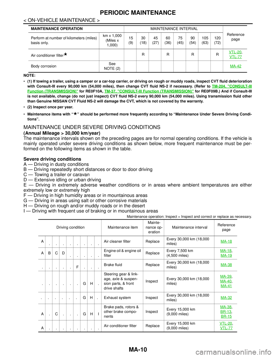
NOTE:
(1) If towing a trailer, using a camper or a car-top carrier, or driving on rough or muddy roads, inspect CVT fluid deterioration
with Consult-III every 90,000 km (54,000 miles), then change CVT fluid NS-2 if necessary. (Refer to TM-204, "
CONSULT-III
Function (TRANSMISSION)" for RE0F10A, TM-37, "CONSULT-III Function (TRANSMISSION)" for RE0F09B.) And if Consult-III
is not available, change (do not just inspect) CVT fluid NS-2 every 90,000 km (54,000 miles). Using transmission fluid other
than Genuine NISSAN CVT Fluid NS-2 will damage the CVT, which is not covered by the warranty.
(2) Inspect once per year.
Maintenance items with “ ” should be performed more frequently according to “Maintenance Under Severe Driving Condi-
tions”.
MAINTENANCE UNDER SEVERE DRIVING CONDITIONS
(Annual Mileage > 30,000 km/year)
The maintenance intervals shown on the preceding pages are for normal operating conditions. If the vehicle is
mainly operated under severe driving conditions as shown below, more frequent maintenance must be per-
formed on the following items as shown in the table.
Severe driving conditions
A — Driving in dusty conditions
B — Driving repeatedly short distances or door to door driving
C — Towing a trailer or caravan
D — Extensive idling or urban driving
E — Driving in extremely adverse weather conditions or in areas where ambient temperatures are either
extremely low or extremely high
F — Driving in high humidity areas or in mountainous areas
G — Driving in areas using salt or other corrosive materials
H — Driving on rough and/or muddy roads or in the desert
I — Driving with frequent use of braking or in mountainous areas
Maintenance operation: Inspect = Inspect and correct or replace as necessary.
Air conditioner filterRRRRVTL-20,
VTL-77
Body corrosionSee
NOTE (2)MA-42
MAINTENANCE OPERATIONMAINTENANCE INTERVAL
Reference
page Perform at number of kilometers (miles)
basis only.km x 1,000
(Miles x
1,000)15
(9)30
(18)45
(27)60
(36)75
(45)90
(54)105
(63)120
(72)
Driving condition Maintenance itemMainte-
nance op-
erationMaintenance intervalReference
page
A
........Air cleaner filter ReplaceEvery 30,000 km (18,000
miles) MA-18
ABCD
.....Engine oil & engine oil
filter ReplaceEvery 7,500 km
(4,500 miles) MA-18,
MA-19
.....F...Brake fluid ReplaceEvery 30,000 km (18,000
miles) MA-38
......GH.Steering gear & link-
age, axle & suspen-
sion parts, & front
drive shaftsInspectEvery 30,000 km (18,000
miles) MA-39
,
MA-40
,
MA-41
......GH.Exhaust system InspectEvery 30,000 km (18,000
miles)MA-32
A.C. . .GHIBrake pads, rotors &
other brake compo-
nentsInspectEvery 15,000 km
(9,000 miles) MA-38
,
BR-13
,
BR-15
A........Air conditioner filter ReplaceEvery 15,000 km
(9,000 miles) VTL-20
,
VTL-77
Page 3225 of 5121
CHASSIS MAINTENANCE
MA-37
< ON-VEHICLE MAINTENANCE >
C
D
E
F
G
H
I
J
K
L
MB
MAN
OA
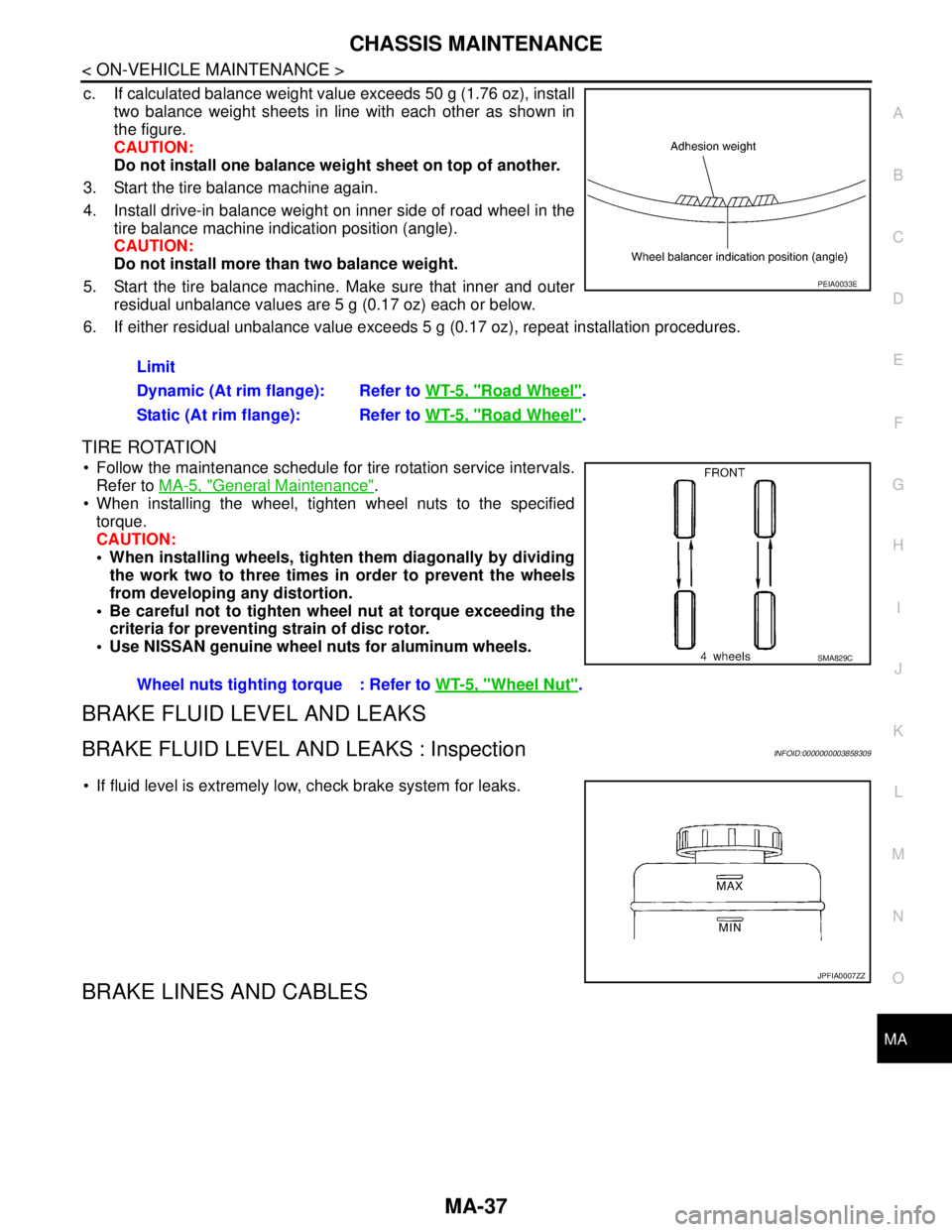
c. If calculated balance weight value exceeds 50 g (1.76 oz), install
two balance weight sheets in line with each other as shown in
the figure.
CAUTION:
Do not install one balance weight sheet on top of another.
3. Start the tire balance machine again.
4. Install drive-in balance weight on inner side of road wheel in the
tire balance machine indication position (angle).
CAUTION:
Do not install more than two balance weight.
5. Start the tire balance machine. Make sure that inner and outer
residual unbalance values are 5 g (0.17 oz) each or below.
6. If either residual unbalance value exceeds 5 g (0.17 oz), repeat installation procedures.
TIRE ROTATION
Follow the maintenance schedule for tire rotation service intervals.
Refer to MA-5, "
General Maintenance".
When installing the wheel, tighten wheel nuts to the specified
torque.
CAUTION:
When installing wheels, tighten them diagonally by dividing
the work two to three times in order to prevent the wheels
from developing any distortion.
Be careful not to tighten wheel nut at torque exceeding the
criteria for preventing strain of disc rotor.
Use NISSAN genuine wheel nuts for aluminum wheels.
BRAKE FLUID LEVEL AND LEAKS
BRAKE FLUID LEVEL AND LEAKS : InspectionINFOID:0000000003858309
If fluid level is extremely low, check brake system for leaks.
BRAKE LINES AND CABLES
Limit
Dynamic (At rim flange): Refer to WT-5, "
Road Wheel".
Static (At rim flange): Refer to WT-5, "
Road Wheel".
PEIA0033E
Wheel nuts tighting torque : Refer to WT-5, "Wheel Nut".
SMA829C
JPFIA0007ZZ
Page 3226 of 5121
MA-38
< ON-VEHICLE MAINTENANCE >
CHASSIS MAINTENANCE
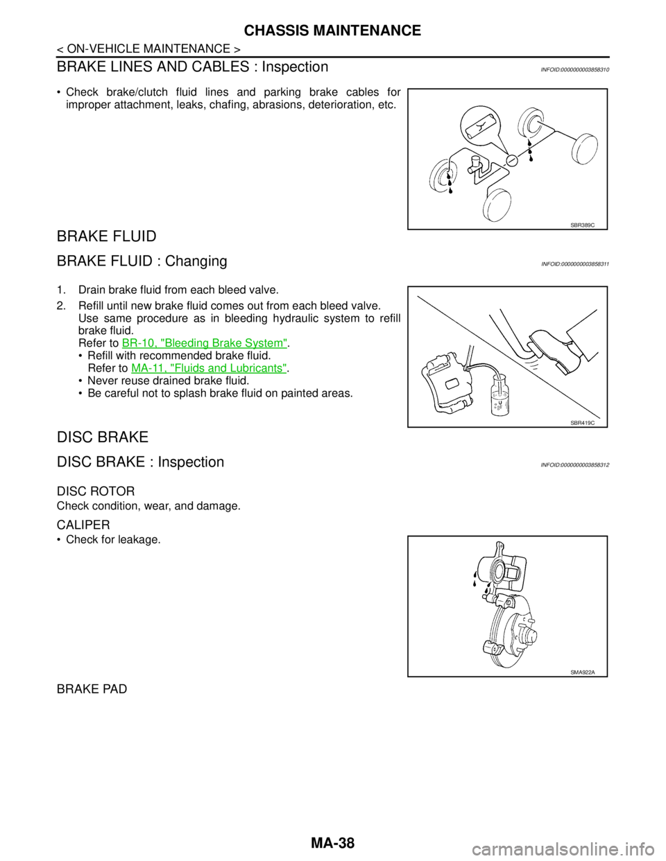
BRAKE LINES AND CABLES : Inspection
INFOID:0000000003858310
Check brake/clutch fluid lines and parking brake cables for
improper attachment, leaks, chafing, abrasions, deterioration, etc.
BRAKE FLUID
BRAKE FLUID : ChangingINFOID:0000000003858311
1. Drain brake fluid from each bleed valve.
2. Refill until new brake fluid comes out from each bleed valve.
Use same procedure as in bleeding hydraulic system to refill
brake fluid.
Refer to BR-10, "
Bleeding Brake System".
Refill with recommended brake fluid.
Refer to MA-11, "
Fluids and Lubricants".
Never reuse drained brake fluid.
Be careful not to splash brake fluid on painted areas.
DISC BRAKE
DISC BRAKE : InspectionINFOID:0000000003858312
DISC ROTOR
Check condition, wear, and damage.
CALIPER
Check for leakage.
BRAKE PAD
SBR389C
SBR419C
SMA922A