oil filter NISSAN TEANA 2008 Service Manual
[x] Cancel search | Manufacturer: NISSAN, Model Year: 2008, Model line: TEANA, Model: NISSAN TEANA 2008Pages: 5121, PDF Size: 69.03 MB
Page 1588 of 5121
![NISSAN TEANA 2008 Service Manual TROUBLE DIAGNOSIS - SPECIFICATION VALUE
EC-127
< COMPONENT DIAGNOSIS >[VQ25DE, VQ35DE]
C
D
E
F
G
H
I
J
K
L
MA
EC
N
P O
NOTE:
Check “A/F ALPHA-B1”, “A/F ALPHA-B2” for approximately 1 minute bec NISSAN TEANA 2008 Service Manual TROUBLE DIAGNOSIS - SPECIFICATION VALUE
EC-127
< COMPONENT DIAGNOSIS >[VQ25DE, VQ35DE]
C
D
E
F
G
H
I
J
K
L
MA
EC
N
P O
NOTE:
Check “A/F ALPHA-B1”, “A/F ALPHA-B2” for approximately 1 minute bec](/img/5/57391/w960_57391-1587.png)
TROUBLE DIAGNOSIS - SPECIFICATION VALUE
EC-127
< COMPONENT DIAGNOSIS >[VQ25DE, VQ35DE]
C
D
E
F
G
H
I
J
K
L
MA
EC
N
P O
NOTE:
Check “A/F ALPHA-B1”, “A/F ALPHA-B2” for approximately 1 minute because they may fluctuate. It is NG
if the indication is out of the SP value even a little.
Is the measurement value within the SP value?
YES >> GO TO 17.
NO-1 >> Less than the SP value: GO TO 2.
NO-2 >> More than the SP value: GO TO 3.
2.CHECK “B/FUEL SCHDL”
Select “B/FUEL SCHDL” in “SPEC” of “DATA MONITOR” mode, and check that the indication is within the SP
value.
Is the measurement value within the SP value?
YES >> GO TO 4.
NO >> More than the SP value: GO TO 19.
3.CHECK “B/FUEL SCHDL”
Select “B/FUEL SCHDL” in “SPEC” of “DATA MONITOR” mode, and check that the indication is within the SP
value.
Is the measurement value within the SP value?
YES >> GO TO 6.
NO-1 >> More than the SP value: GO TO 6.
NO-2 >> Less than the SP value: GO TO 25.
4.CHECK “A/F ALPHA-B1”, “A/F ALPHA-B2”
1. Stop the engine.
2. Disconnect PCV hose, and then plug it.
3. Start engine.
4. Select “A/F ALPHA-B1”, “A/F ALPHA-B2” in “SPEC” of “DATA MONITOR” mode, and check that the each
indication is within the SP value.
Is the measurement value within the SP value?
YES >> GO TO 5.
NO >> GO TO 6.
5.CHANGE ENGINE OIL
1. Stop the engine.
2. Change engine oil.
NOTE:
This symptom may occur when a large amount of gasoline is mixed with engine oil because of driving
conditions (such as when engine oil temperature does not rise enough since a journey distance is too
short during winter). The symptom will not be detected after changing engine oil or changing driving con-
ditions.
>> INSPECTION END
6.CHECK FUEL PRESSURE
Check fuel pressure. (Refer to EC-411, "
Inspection".)
Is the inspection result normal?
YES >> GO TO 9.
NO-1 >> Fuel pressure is too high: Replace “fuel filter and fuel pump assembly” and then. GO TO 8.
NO-2 >> Fuel pressure is too low: GO TO 7.
7.DETECT MALFUNCTIONING PART
Check fuel hoses and fuel tubes for clogging.
Is the inspection result normal?
YES >> Replace “fuel filter and fuel pump assembly” and then GO TO 8.
NO >> Repair or replace malfunctioning part and then GO TO 8.
8.CHECK “A/F ALPHA-B1”, “A/F ALPHA-B2”
Page 1673 of 5121
![NISSAN TEANA 2008 Service Manual EC-212
< COMPONENT DIAGNOSIS >[VQ25DE, VQ35DE]
P0300, P0301, P0302, P0303, P0304, P0305, P0306 MISFIRE
7.CHECK SPARK PLUG
Check the initial spark plug for fouling, etc.
Is the inspection result normal NISSAN TEANA 2008 Service Manual EC-212
< COMPONENT DIAGNOSIS >[VQ25DE, VQ35DE]
P0300, P0301, P0302, P0303, P0304, P0305, P0306 MISFIRE
7.CHECK SPARK PLUG
Check the initial spark plug for fouling, etc.
Is the inspection result normal](/img/5/57391/w960_57391-1672.png)
EC-212
< COMPONENT DIAGNOSIS >[VQ25DE, VQ35DE]
P0300, P0301, P0302, P0303, P0304, P0305, P0306 MISFIRE
7.CHECK SPARK PLUG
Check the initial spark plug for fouling, etc.
Is the inspection result normal?
YES >> Replace spark plug(s) with standard type one(s). For
spark plug type, refer to EM-136, "
Spark Plug".
NO >> Repair or clean spark plug. Then GO TO 8.
8.CHECK FUNCTION OF IGNITION COIL-III
1. Reconnect the initial spark plugs.
2. Crank engine for about 3 seconds, and recheck whether spark is generated between the spark plug and
the grounded portion.
Is the inspection result normal?
YES >> INSPECTION END
NO >> Replace spark plug(s) with standard type one(s). For spark plug type, refer to EM-136, "
Spark
Plug".
9.CHECK COMPRESSION PRESSURE
Check compression pressure. Refer to EM-22, "
Inspection".
Is the inspection result normal?
YES >> GO TO 10.
NO >> Check pistons, piston rings, valves, valve seats and cylinder head gaskets.
10.CHECK FUEL PRESSURE
1. Install all removed parts.
2. Release fuel pressure to zero. Refer to EC-411, "
Inspection".
3. Install fuel pressure gauge and check fuel pressure. Refer to EC-411, "
Inspection".
Is the inspection result normal?
YES >> GO TO 12.
NO >> GO TO 11.
11 .DETECT MALFUNCTIONING PART
Check fuel hoses and fuel tubes for clogging.
Is the inspection result normal?
YES >> Replace “fuel filter and fuel pump assembly”.
NO >> Repair or replace malfunctioning part.
12.CHECK IGNITION TIMING
Check idle speed and ignition timing.
For procedure, refer to EC-11, "
BASIC INSPECTION : Special Repair Requirement".
For specification, refer to EC-414, "
Idle Speed" and EC-414, "Ignition Timing".
Is the inspection result normal?
YES >> GO TO 13.
NO >> Follow the EC-11, "
BASIC INSPECTION : Special Repair Requirement".
13.CHECK A/F SENSOR 1 INPUT SIGNAL CIRCUIT
1. Turn ignition switch OFF.
SEF156I
Spark should be generated.
At idle: Approximately 350 kPa (3.50 bar, 3.57 kg/cm
2, 51 psi)
Page 1864 of 5121
![NISSAN TEANA 2008 Service Manual ENGINE CONTROL SYSTEM SYMPTOMS
EC-403
< SYMPTOM DIAGNOSIS >[VQ25DE, VQ35DE]
C
D
E
F
G
H
I
J
K
L
MA
EC
N
P O
1 - 6: The numbers refer to the order of inspection.Va l v e
mecha-
nismTiming chain
55555 NISSAN TEANA 2008 Service Manual ENGINE CONTROL SYSTEM SYMPTOMS
EC-403
< SYMPTOM DIAGNOSIS >[VQ25DE, VQ35DE]
C
D
E
F
G
H
I
J
K
L
MA
EC
N
P O
1 - 6: The numbers refer to the order of inspection.Va l v e
mecha-
nismTiming chain
55555](/img/5/57391/w960_57391-1863.png)
ENGINE CONTROL SYSTEM SYMPTOMS
EC-403
< SYMPTOM DIAGNOSIS >[VQ25DE, VQ35DE]
C
D
E
F
G
H
I
J
K
L
MA
EC
N
P O
1 - 6: The numbers refer to the order of inspection.Va l v e
mecha-
nismTiming chain
55555 55 5EM-65
CamshaftEM-84
Intake valve timing controlEM-65
Intake valve
3EM-97
Exhaust valve
Exhaust Exhaust manifold/Tube/Muffler/
Gasket
55555 55 5EM-34
, EX-
4Three way catalyst
Lubrica-
tionOil pan/Oil strainer/Oil pump/Oil
filter/Oil gallery/Oil cooler
55555 55 5LU-7
, LU-
10, LU-11,
LU-13
Oil level (Low)/Filthy oilLU-7
Cooling
Radiator/Hose/Radiator filler cap
55555 55 45CO-12,
CO-12
Thermostat 5CO-23
Water pumpCO-18
Water galleryCO-2
Cooling fan
5CO-16
Coolant level (Low)/Contaminat-
ed coolantCO-8
NVIS (NISSAN Vehicle Immobilizer System —
NATS)11SEC-14
SYMPTOM
Reference
page
HARD/NO START/RESTART (EXCP. HA)
ENGINE STALL
HESITATION/SURGING/FLAT SPOT
SPARK KNOCK/DETONATION
LACK OF POWER/POOR ACCELERATION
HIGH IDLE/LOW IDLE
ROUGH IDLE/HUNTING
IDLING VIBRATION
SLOW/NO RETURN TO IDLE
OVERHEATS/WATER TEMPERATURE HIGH
EXCESSIVE FUEL CONSUMPTION
EXCESSIVE OIL CONSUMPTION
BATTERY DEAD (UNDER CHARGE)
Warranty symptom code AA AB AC AD AE AF AG AH AJ AK AL AM HA
Page 1876 of 5121
EM-1
ENGINE
C
D
E
F
G
H
I
J
K
L
M
SECTION EM
A
EM
N
O
P
CONTENTS
ENGINE MECHANICAL
SYMPTOM DIAGNOSIS ...............................3
NOISE, VIBRATION AND HARSHNESS
(NVH) TROUBLESHOOTING .............................
3
NVH Troubleshooting - Engine Noise .......................3
Use the Chart Below to Help You Find the Cause
of the Symptom .........................................................
4
PRECAUTION ...............................................5
PRECAUTIONS ...................................................5
Precaution for Procedure without Cowl Top Cover ......5
Precaution for Supplemental Restraint System
(SRS) "AIR BAG" and "SEAT BELT PRE-TEN-
SIONER" ...................................................................
5
Precaution Necessary for Steering Wheel Rota-
tion after Battery Disconnect .....................................
5
Precaution for Drain Engine Coolant and Engine
Oil ..............................................................................
6
Precaution for Disconnecting Fuel Piping .................6
Precaution for Removal and Disassembly ................6
Precaution for Inspection, Repair and Replace-
ment ..........................................................................
6
Precaution for Assembly and Installation ..................6
Precaution for Angle Tightening ................................6
Precaution for Liquid Gasket .....................................7
PREPARATION ............................................8
PREPARATION ...................................................8
Special Service Tool .................................................8
Commercial Service Tool ..........................................9
ON-VEHICLE MAINTENANCE ....................12
DRIVE BELT .......................................................12
Exploded View ........................................................12
Checking .................................................................12
Tension Adjustment ................................................12
Removal and Installation .........................................12
AIR CLEANER FILTER ......................................14
Removal and Installation .........................................14
SPARK PLUG ...................................................15
Exploded View .........................................................15
Removal and Installation .........................................15
Inspection ................................................................16
CAMSHAFT VALVE CLEARANCE ..................17
Inspection and Adjustment ......................................17
COMPRESSION PRESSURE ...........................22
Inspection ................................................................22
ON-VEHICLE REPAIR .................................24
ENGINE COVER ...............................................24
Exploded View .........................................................24
Removal and Installation .........................................24
DRIVE BELT AUTO TENSIONER AND IDLER
PULLEY .............................................................
25
Exploded View .........................................................25
Removal and Installation .........................................25
AIR CLEANER AND AIR DUCT .......................26
Exploded View .........................................................26
Removal and Installation .........................................26
Inspection ................................................................27
INTAKE MANIFOLD COLLECTOR ..................28
Exploded View .........................................................28
Removal and Installation .........................................29
INTAKE MANIFOLD .........................................32
Exploded View .........................................................32
Removal and Installation .........................................32
Inspection ................................................................33
EXHAUST MANIFOLD AND THREE WAY
CATALYST ........................................................
34
Exploded View .........................................................34
Removal and Installation .........................................34
Inspection ................................................................37
Page 1913 of 5121
EM-38
< ON-VEHICLE REPAIR >
OIL PAN AND OIL STRAINER
OIL PAN AND OIL STRAINER
Exploded ViewINFOID:0000000003802261
Removal and InstallationINFOID:0000000003802262
REMOVAL
CAUTION:
To avoid the danger of being scalded, never drain engine oil when the engine is hot.
NOTE:
When removing oil pan (lower) or oil strainer only, take step 1 then step 18 and 19.
1. Drain engine oil. Refer to LU-8, "
Draining".
CAUTION:
Never spill engine oil on drive belt.
2. Drain engine coolant. Refer to CO-8, "
Draining".
CAUTION:
Never spill engine coolant on drive belt.
3. Remove following parts:
Front road wheel and tires (RH and LH)
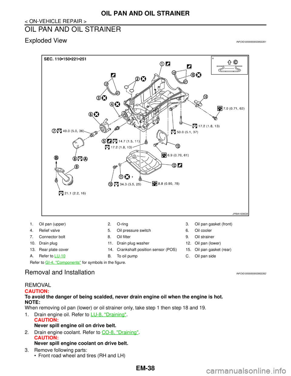
1. Oil pan (upper) 2. O-ring 3. Oil pan gasket (front)
4. Relief valve 5. Oil pressure switch 6. Oil cooler
7. Connector bolt 8. Oil filter 9. Oil strainer
10. Drain plug 11. Drain plug washer 12. Oil pan (lower)
13. Rear plate cover 14. Crankshaft position sensor (POS) 15. Oil pan gasket (rear)
A. Refer to LU-10
B. To oil pump C. Oil pan side
Refer to GI-4, "
Components" for symbols in the figure.
JPBIA1636GB
Page 1914 of 5121
OIL PAN AND OIL STRAINER
EM-39
< ON-VEHICLE REPAIR >
C
D
E
F
G
H
I
J
K
L
MA
EM
N
P O
Splash guard (RH and LH): Refer to EXT-22, "FENDER PROTECTOR : Exploded View".
Exhaust front tube: Refer to EX-5, "
Exploded View".
Drive belt: Refer to EM-12, "
Removal and Installation".
4. Remove A/C compressor with piping connected, and temporarily secure it to aside. Refer to HA-36,
"Exploded View".
5. Remove oil level gauge. Refer to EM-96, "
Exploded View".
6. Remove front drive shaft (RH). Refer to FAX-16, "
Exploded View".
7. Remove three way catalyst (bank 1 and bank 2) from exhaust manifolds (bank 1 and bank 2). Refer to
EM-34, "
Exploded View".
8. Remove oil pressure switch.
9. Remove oil filter. Refer to LU-10, "
Removal and Installation".
10. Remove oil cooler and water pipes. Refer to LU-11, "
Exploded View".
11. Support transaxle assembly with a suitable jack.
CAUTION:
When setting the transmission jack, be careful not to allow it to collide against the drain plug.
12. Support front suspension member with a suitable jack.
13. Remove engine mounting insulator (rear). Refer to EM-67, "
Exploded View".
14. Remove engine mounting insulator (LH) mounting bolts from transaxle. Refer to EM-67, "
Exploded View".
15. Remove rear torque rod through bolts from rear torque rod bracket. Refer to EM-67, "
Exploded View".
16. Remove member stay, front suspension member fixing bolts and nuts. Refer to FSU-16, "
Exploded View".
17. Lower the jack for the front suspension member to the height.
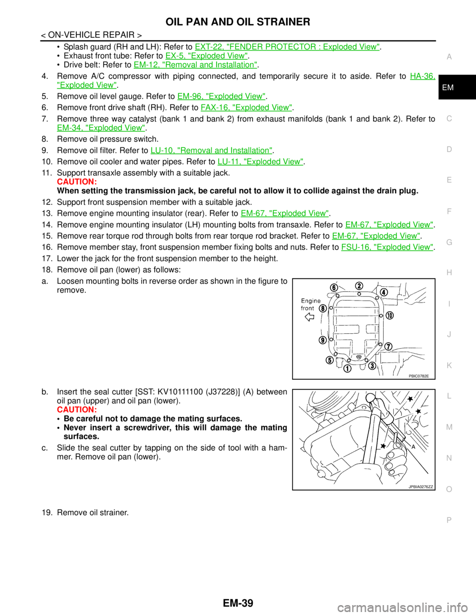
18. Remove oil pan (lower) as follows:
a. Loosen mounting bolts in reverse order as shown in the figure to
remove.
b. Insert the seal cutter [SST: KV10111100 (J37228)] (A) between
oil pan (upper) and oil pan (lower).
CAUTION:
Be careful not to damage the mating surfaces.
Never insert a screwdriver, this will damage the mating
surfaces.
c. Slide the seal cutter by tapping on the side of tool with a ham-
mer. Remove oil pan (lower).
19. Remove oil strainer.
PBIC0782E
JPBIA0276ZZ
Page 1967 of 5121
EM-92
< DISASSEMBLY AND ASSEMBLY >
CAMSHAFT
b. Disconnect ignition coil and injector harness connectors. Refer to EM-49, "Exploded View" and EM-44,
"Exploded View".
3. Remove intake valve timing control solenoid valve. Refer to EM-79, "
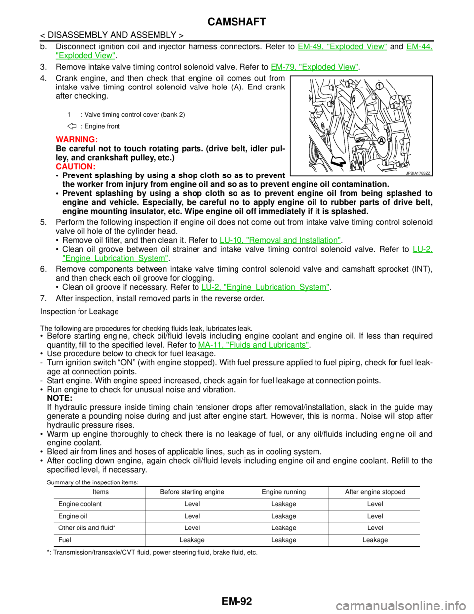
Exploded View".
4. Crank engine, and then check that engine oil comes out from
intake valve timing control solenoid valve hole (A). End crank
after checking.
WARNING:
Be careful not to touch rotating parts. (drive belt, idler pul-
ley, and crankshaft pulley, etc.)
CAUTION:
Prevent splashing by using a shop cloth so as to prevent
the worker from injury from engine oil and so as to prevent engine oil contamination.
Prevent splashing by using a shop cloth so as to prevent engine oil from being splashed to
engine and vehicle. Especially, be careful no to apply engine oil to rubber parts of drive belt,
engine mounting insulator, etc. Wipe engine oil off immediately if it is splashed.
5. Perform the following inspection if engine oil does not come out from intake valve timing control solenoid
valve oil hole of the cylinder head.
Remove oil filter, and then clean it. Refer to LU-10, "
Removal and Installation".
Clean oil groove between oil strainer and intake valve timing control solenoid valve. Refer to LU-2,
"EngineLubricationSystem".
6. Remove components between intake valve timing control solenoid valve and camshaft sprocket (INT),
and then check each oil groove for clogging.
Clean oil groove if necessary. Refer to LU-2, "
EngineLubricationSystem".
7. After inspection, install removed parts in the reverse order.
Inspection for Leakage
The following are procedures for checking fluids leak, lubricates leak. Before starting engine, check oil/fluid levels including engine coolant and engine oil. If less than required
quantity, fill to the specified level. Refer to MA-11, "
Fluids and Lubricants".
Use procedure below to check for fuel leakage.
- Turn ignition switch “ON” (with engine stopped). With fuel pressure applied to fuel piping, check for fuel leak-
age at connection points.
- Start engine. With engine speed increased, check again for fuel leakage at connection points.
Run engine to check for unusual noise and vibration.
NOTE:
If hydraulic pressure inside timing chain tensioner drops after removal/installation, slack in the guide may
generate a pounding noise during and just after engine start. However, this is normal. Noise will stop after
hydraulic pressure rises.
Warm up engine thoroughly to check there is no leakage of fuel, or any oil/fluids including engine oil and
engine coolant.
Bleed air from lines and hoses of applicable lines, such as in cooling system.
After cooling down engine, again check oil/fluid levels including engine oil and engine coolant. Refill to the
specified level, if necessary.
Summary of the inspection items:
*: Transmission/transaxle/CVT fluid, power steering fluid, brake fluid, etc.1 : Valve timing control cover (bank 2)
: Engine front
JPBIA1783ZZ
Items Before starting engine Engine running After engine stopped
Engine coolant Level Leakage Level
Engine oil Level Leakage Level
Other oils and fluid* Level Leakage Level
Fuel Leakage Leakage Leakage
Page 2521 of 5121
GI-28
< PRECAUTION >
PRECAUTIONS
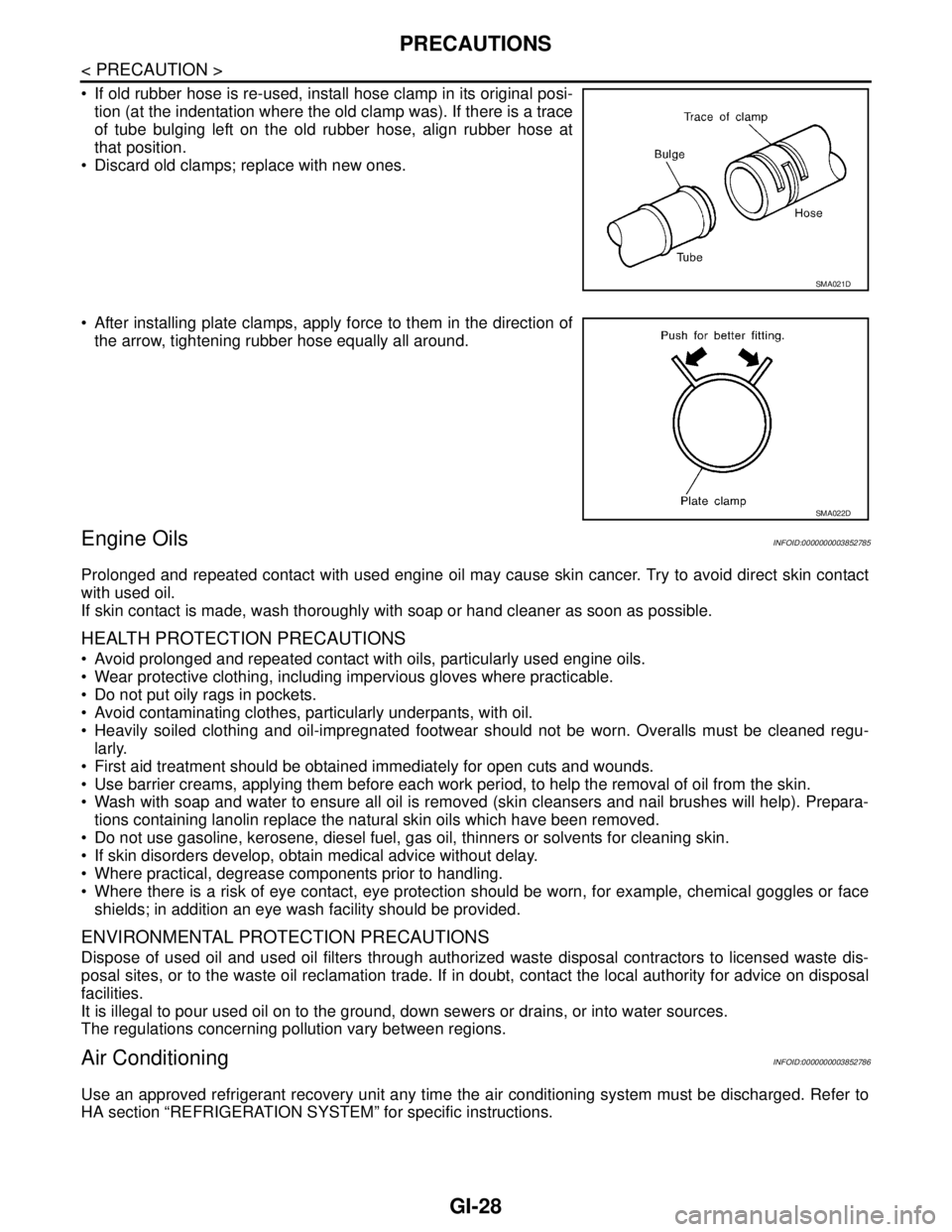
If old rubber hose is re-used, install hose clamp in its original posi-
tion (at the indentation where the old clamp was). If there is a trace
of tube bulging left on the old rubber hose, align rubber hose at
that position.
Discard old clamps; replace with new ones.
After installing plate clamps, apply force to them in the direction of
the arrow, tightening rubber hose equally all around.
Engine OilsINFOID:0000000003852785
Prolonged and repeated contact with used engine oil may cause skin cancer. Try to avoid direct skin contact
with used oil.
If skin contact is made, wash thoroughly with soap or hand cleaner as soon as possible.
HEALTH PROTECTION PRECAUTIONS
Avoid prolonged and repeated contact with oils, particularly used engine oils.
Wear protective clothing, including impervious gloves where practicable.
Do not put oily rags in pockets.
Avoid contaminating clothes, particularly underpants, with oil.
Heavily soiled clothing and oil-impregnated footwear should not be worn. Overalls must be cleaned regu-
larly.
First aid treatment should be obtained immediately for open cuts and wounds.
Use barrier creams, applying them before each work period, to help the removal of oil from the skin.
Wash with soap and water to ensure all oil is removed (skin cleansers and nail brushes will help). Prepara-
tions containing lanolin replace the natural skin oils which have been removed.
Do not use gasoline, kerosene, diesel fuel, gas oil, thinners or solvents for cleaning skin.
If skin disorders develop, obtain medical advice without delay.
Where practical, degrease components prior to handling.
Where there is a risk of eye contact, eye protection should be worn, for example, chemical goggles or face
shields; in addition an eye wash facility should be provided.
ENVIRONMENTAL PROTECTION PRECAUTIONS
Dispose of used oil and used oil filters through authorized waste disposal contractors to licensed waste dis-
posal sites, or to the waste oil reclamation trade. If in doubt, contact the local authority for advice on disposal
facilities.
It is illegal to pour used oil on to the ground, down sewers or drains, or into water sources.
The regulations concerning pollution vary between regions.
Air ConditioningINFOID:0000000003852786
Use an approved refrigerant recovery unit any time the air conditioning system must be discharged. Refer to
HA section “REFRIGERATION SYSTEM” for specific instructions.
SMA021D
SMA022D
Page 3173 of 5121
LU-1
ENGINE
C
DE
F
G H
I
J
K L
M
SECTION LU
A
LU
N
O P
CONTENTS
ENGINE LUBRICATION SYSTEM
FUNCTION DIAGNOSIS .. .............................2
DESCRIPTION ............................................... .....2
Engine Lubrication System ................................ ......2
Engine Lubrication System Schematic ......................3
PRECAUTION ...............................................4
PRECAUTIONS .............................................. .....4
Precaution for Liquid Gasket ............................... ......4
PREPARATION ............................................5
PREPARATION .............................................. .....5
Special Service Tool ........................................... ......5
Commercial Service Tool ..........................................5
ON-VEHICLE MAINTENANCE .....................7
ENGINE OIL ................................................... .....7
Inspection ............................................................ ......7
Draining .....................................................................8
Refilling .....................................................................9
OIL FILTER ........................................................10
Removal and Installation ..................................... ....10
Inspection ................................................................10
ON-VEHICLE REPAIR .................................11
OIL COOLER ....................................................11
Exploded View ..................................................... ....11
Removal and Installation .........................................11
Inspection ................................................................12
DISASSEMBLY AND ASSEMBLY ..............13
OIL PUMP .........................................................13
Exploded View ..................................................... ....13
Removal and Installation .........................................13
Disassembly and Assembly .....................................13
Inspection ................................................................14
SERVICE DATA AND SPECIFICATIONS
(SDS) ............... .............................................
16
SERVICE DATA AND SPECIFICATIONS
(SDS) .................................................................
16
Periodical Maintenance Specification ................ ....16
Engine Oil Pressure ...............................................16
Oil Pump .................................................................16
Regulator Valve ......................................................16
Page 3177 of 5121
PREPARATION
LU-5
< PREPARATION >
C
D
E
F
G
H
I
J
K
L
MA
LU
N
P O
PREPARATION
PREPARATION
Special Service ToolINFOID:0000000003793119
Commercial Service ToolINFOID:0000000003793120
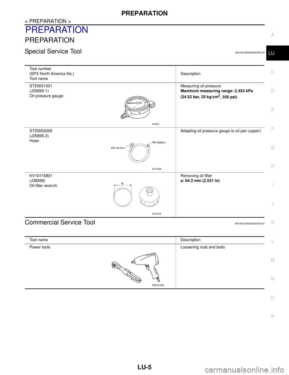
Tool number
(SPX North America No.)
Tool nameDescription
ST25051001
(J25695-1)
Oil pressure gaugeMeasuring oil pressure
Maximum measuring range: 2,452 kPa
(24.52 bar, 25 kg/cm
2, 356 psi)
ST25052000
(J25695-2)
HoseAdapting oil pressure gauge to oil pan (upper)
KV10115801
(J38956)
Oil filter wrenchRemoving oil filter
a: 64.3 mm (2.531 in)
NT050
S-NT559
S-NT375
Tool nameDescription
Power toolsLoosening nuts and bolts
PBIC0190E