brake rotor NISSAN TEANA 2008 Owner's Guide
[x] Cancel search | Manufacturer: NISSAN, Model Year: 2008, Model line: TEANA, Model: NISSAN TEANA 2008Pages: 5121, PDF Size: 69.03 MB
Page 3227 of 5121

CHASSIS MAINTENANCE
MA-39
< ON-VEHICLE MAINTENANCE >
C
D
E
F
G
H
I
J
K
L
MB
MAN
OA
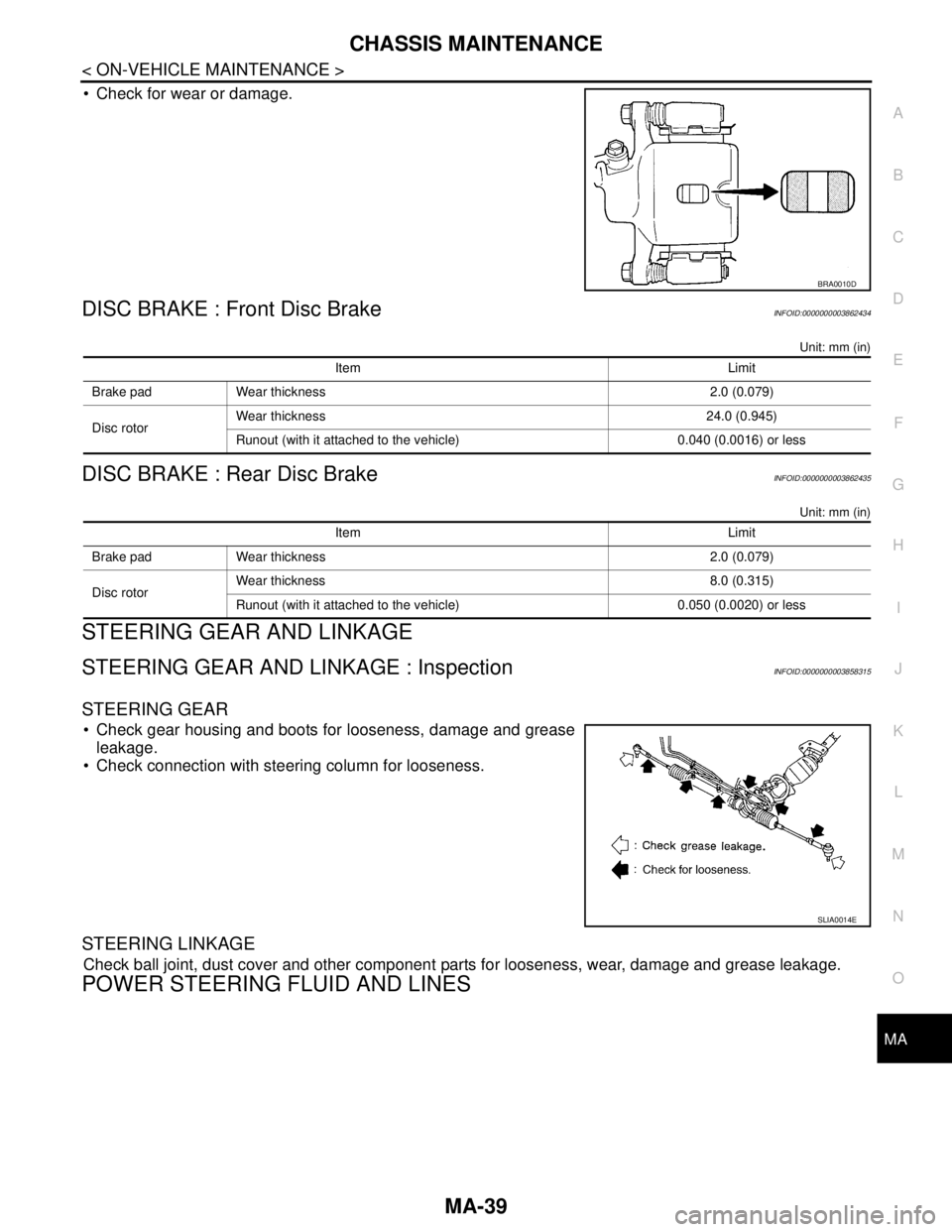
Check for wear or damage.
DISC BRAKE : Front Disc BrakeINFOID:0000000003862434
Unit: mm (in)
DISC BRAKE : Rear Disc BrakeINFOID:0000000003862435
Unit: mm (in)
STEERING GEAR AND LINKAGE
STEERING GEAR AND LINKAGE : InspectionINFOID:0000000003858315
STEERING GEAR
Check gear housing and boots for looseness, damage and grease
leakage.
Check connection with steering column for looseness.
STEERING LINKAGE
Check ball joint, dust cover and other component parts for looseness, wear, damage and grease leakage.
POWER STEERING FLUID AND LINES
BRA0010D
Item Limit
Brake pad Wear thickness 2.0 (0.079)
Disc rotorWear thickness 24.0 (0.945)
Runout (with it attached to the vehicle) 0.040 (0.0016) or less
Item Limit
Brake pad Wear thickness 2.0 (0.079)
Disc rotorWear thickness 8.0 (0.315)
Runout (with it attached to the vehicle) 0.050 (0.0020) or less
SLIA0014E
Page 3383 of 5121

PB-2
< ON-VEHICLE MAINTENANCE >
PARKING BRAKE SYSTEM
ON-VEHICLE MAINTENANCE
PARKING BRAKE SYSTEM
Inspection and AdjustmentINFOID:0000000003811312
INSPECTION
Pedal Stroke
1. Operate the parking brake pedal with a force of 196 N (20 kg, 44 lb). Check that the pedal stroke is within
the specified number of notches. (Check it by listening to the clicks of the ratchet.)
2. When brake warning lamp turns ON, check that the pedal stroke is within the specified number of
notches. (Check it by listening to the clicks of the ratchet.)
Inspect Components
• Check each component for installation condition such as looseness.
Check the device assembly for bend, damage and cracks. Replace if necessary.
Check the cables for wear, damage and cracks. Replace if necessary.
Check the parking brake switch, and replace it if necessary. Refer to BRC-41, "
Diagnosis Procedure" (with-
out VDC), BRC-124, "
Component Inspection" (with VDC).
ADJUSTMENT
1. Remove rear tires.
2. Fix the disc rotor using wheel nuts.
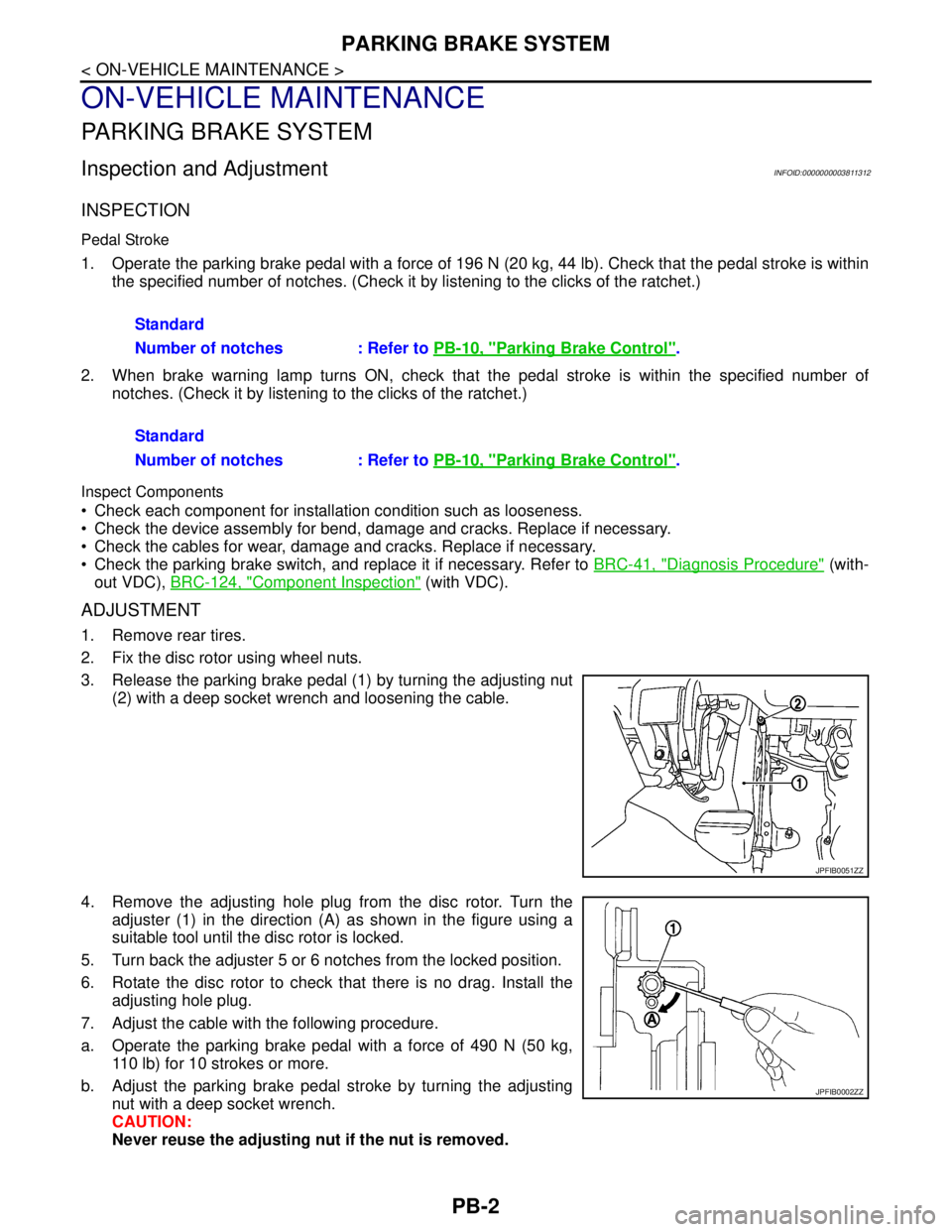
3. Release the parking brake pedal (1) by turning the adjusting nut
(2) with a deep socket wrench and loosening the cable.
4. Remove the adjusting hole plug from the disc rotor. Turn the
adjuster (1) in the direction (A) as shown in the figure using a
suitable tool until the disc rotor is locked.
5. Turn back the adjuster 5 or 6 notches from the locked position.
6. Rotate the disc rotor to check that there is no drag. Install the
adjusting hole plug.
7. Adjust the cable with the following procedure.
a. Operate the parking brake pedal with a force of 490 N (50 kg,
110 lb) for 10 strokes or more.
b. Adjust the parking brake pedal stroke by turning the adjusting
nut with a deep socket wrench.
CAUTION:
Never reuse the adjusting nut if the nut is removed.Standard
Number of notches : Refer to PB-10, "
Parking Brake Control".
Standard
Number of notches : Refer to PB-10, "
Parking Brake Control".
JPFIB0051ZZ
JPFIB0002ZZ
Page 3384 of 5121

PARKING BRAKE SYSTEM
PB-3
< ON-VEHICLE MAINTENANCE >
C
D
E
G
H
I
J
K
L
MA
B
PB
N
O
P
c. Operate the parking brake pedal with a force of 196 N (20 kg, 44 lb). Check that the pedal stroke is within
the specified number of notches. (Check it by listening to the clicks of the ratchet.)
d. Rotate the disc rotor with the parking brake pedal released and check that there is no drag. Refer to PB-8,
"Inspection and Adjustment". Standard
Number of notches : Refer to PB-10, "
Parking Brake Control".
Page 3388 of 5121

PARKING BRAKE SHOE
PB-7
< ON-VEHICLE REPAIR >
C
D
E
G
H
I
J
K
L
MA
B
PB
N
O
P
PARKING BRAKE SHOE
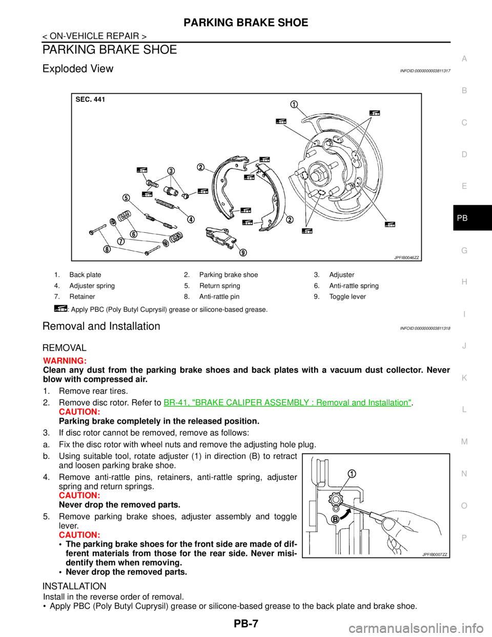
Exploded ViewINFOID:0000000003811317
Removal and InstallationINFOID:0000000003811318
REMOVAL
WARNING:
Clean any dust from the parking brake shoes and back plates with a vacuum dust collector. Never
blow with compressed air.
1. Remove rear tires.
2. Remove disc rotor. Refer to BR-41, "
BRAKE CALIPER ASSEMBLY : Removal and Installation".
CAUTION:
Parking brake completely in the released position.
3. If disc rotor cannot be removed, remove as follows:
a. Fix the disc rotor with wheel nuts and remove the adjusting hole plug.
b. Using suitable tool, rotate adjuster (1) in direction (B) to retract
and loosen parking brake shoe.
4. Remove anti-rattle pins, retainers, anti-rattle spring, adjuster
spring and return springs.
CAUTION:
Never drop the removed parts.
5. Remove parking brake shoes, adjuster assembly and toggle
lever.
CAUTION:
• The parking brake shoes for the front side are made of dif-
ferent materials from those for the rear side. Never misi-
dentify them when removing.
Never drop the removed parts.
INSTALLATION
Install in the reverse order of removal.
Apply PBC (Poly Butyl Cuprysil) grease or silicone-based grease to the back plate and brake shoe.
1. Back plate 2. Parking brake shoe 3. Adjuster
4. Adjuster spring 5. Return spring 6. Anti-rattle spring
7. Retainer 8. Anti-rattle pin 9. Toggle lever
: Apply PBC (Poly Butyl Cuprysil) grease or silicone-based grease.
JPFIB0046ZZ
JPFIB0007ZZ
Page 3729 of 5121

RAX-4
< ON-VEHICLE REPAIR >
REAR WHEEL HUB AND HOUSING
ON-VEHICLE REPAIR
REAR WHEEL HUB AND HOUSING
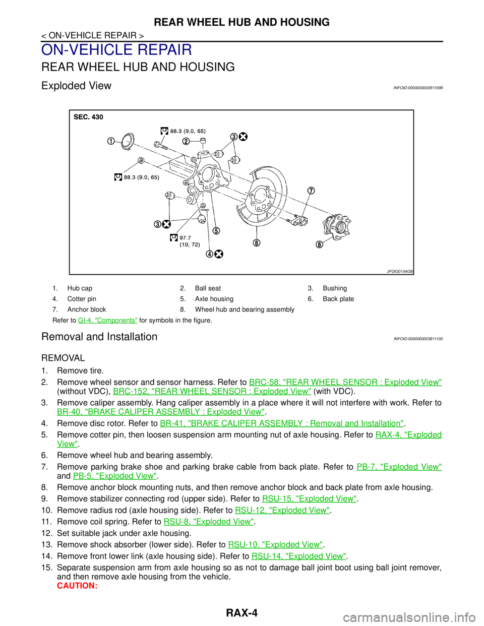
Exploded ViewINFOID:0000000003811099
Removal and InstallationINFOID:0000000003811100
REMOVAL
1. Remove tire.
2. Remove wheel sensor and sensor harness. Refer to BRC-58, "
REAR WHEEL SENSOR : Exploded View"
(without VDC), BRC-152, "REAR WHEEL SENSOR : Exploded View" (with VDC).
3. Remove caliper assembly. Hang caliper assembly in a place where it will not interfere with work. Refer to
BR-40, "
BRAKE CALIPER ASSEMBLY : Exploded View".
4. Remove disc rotor. Refer to BR-41, "
BRAKE CALIPER ASSEMBLY : Removal and Installation".
5. Remove cotter pin, then loosen suspension arm mounting nut of axle housing. Refer to RAX-4, "
Exploded
View".
6. Remove wheel hub and bearing assembly.
7. Remove parking brake shoe and parking brake cable from back plate. Refer to PB-7, "
Exploded View"
and PB-5, "Exploded View".
8. Remove anchor block mounting nuts, and then remove anchor block and back plate from axle housing.
9. Remove stabilizer connecting rod (upper side). Refer to RSU-15, "
Exploded View".
10. Remove radius rod (axle housing side). Refer to RSU-12, "
Exploded View".
11. Remove coil spring. Refer to RSU-8, "
Exploded View".
12. Set suitable jack under axle housing.
13. Remove shock absorber (lower side). Refer to RSU-10, "
Exploded View".
14. Remove front lower link (axle housing side). Refer to RSU-14, "
Exploded View".
15. Separate suspension arm from axle housing so as not to damage ball joint boot using ball joint remover,
and then remove axle housing from the vehicle.
CAUTION:
1. Hub cap 2. Ball seat 3. Bushing
4. Cotter pin 5. Axle housing 6. Back plate
7. Anchor block 8. Wheel hub and bearing assembly
Refer to GI-4, "
Components" for symbols in the figure.
JPDIG0104GB