weight NISSAN TEANA 2008 Owner's Guide
[x] Cancel search | Manufacturer: NISSAN, Model Year: 2008, Model line: TEANA, Model: NISSAN TEANA 2008Pages: 5121, PDF Size: 69.03 MB
Page 4886 of 5121
![NISSAN TEANA 2008 Owners Guide PREPARATION
VTL-75
< PREPARATION >[WITH 7 INCH DISPLAY]
C
D
E
F
G
H
J
K
L
MA
B
VTL
N
O
PCommercial Service ToolINFOID:0000000003894468
Sealant or/and LubricantINFOID:0000000003894469
HFC-134a (R-134a)](/img/5/57391/w960_57391-4885.png "NISSAN TEANA 2008 Owners Guide PREPARATION
VTL-75
< PREPARATION >[WITH 7 INCH DISPLAY]
C
D
E
F
G
H
J
K
L
MA
B
VTL
N
O
PCommercial Service ToolINFOID:0000000003894468
Sealant or/and LubricantINFOID:0000000003894469
HFC-134a (R-134a)")
PREPARATION
VTL-75
< PREPARATION >[WITH 7 INCH DISPLAY]
C
D
E
F
G
H
J
K
L
MA
B
VTL
N
O
PCommercial Service ToolINFOID:0000000003894468
Sealant or/and LubricantINFOID:0000000003894469
HFC-134a (R-134a) Service Tool and Equipment Never mix HFC-134a (R-134a) refrigerant and/or its specified lubricant with CFC-12 (R-12) refrigerant and/
or its lubricant.
Separate and non-interchangeable service equipment must be used for handling each type of refrigerant/
lubricant.
Refrigerant container fittings, service hose fittings and service equipment fittings (equipment which handles
refrigerant and/or lubricant) are different between CFC-12 (R-12) and HFC-134a (R-134a). This is to avoid
mixed use of the refrigerants/lubricant.
Never use adapters that convert one size fitting to another: refrigerant/lubricant contamination occurs and
compressor malfunction may result.
Service couplers
High-pressure side coupler
Low-pressure side couplerHose fitting to service hose:
M14 x 1.5 fitting is optional or permanently
attached.
Refrigerant weight scaleFor measuring of refrigerant
Fitting size: Thread size
1/2
″-16 ACME
Va c u u m p u m p
(Including the isolator valve)Capacity:
Air displacement: 4 CFM
Micron rating: 20 microns
Oil capacity: 482 g (17 oz.)
Fitting size: Thread size
1/2
″-16 ACME Tool number
(SPX-North America No.)
Tool nameDescription
S-NT202
S-NT200
S-NT203
Tool name Description
Remover toolsRemove clips, pawls, metal clips
PIIB7923J
Page 5010 of 5121
ROAD WHEEL TIRE ASSEMBLY
WT-3
< ON-VEHICLE REPAIR >
C
D
F
G
H
I
J
K
L
MA
B
WT
N
O
P
ON-VEHICLE REPAIR
ROAD WHEEL TIRE ASSEMBLY
AdjustmentINFOID:0000000003812917
BALANCING WHEELS (BONDING WEIGHT TYPE)
Preparation Before Adjustment
Using releasing agent, remove double-faced adhesive tape from the road wheel.
CAUTION:
• Be careful not to scratch the road wheel during removal.
After removing double-faced adhesive tape, wipe clean traces of releasing agent from the road
wheel.
Wheel Balance Adjustment
If a tire balance machine has adhesion balance weight mode settings and drive-in weight mode setting, select
and adjust a drive-in weight mode suitable for road wheels.
1. Set road wheel on tire balance machine using the center hole as a guide. Start the tire balance machine.
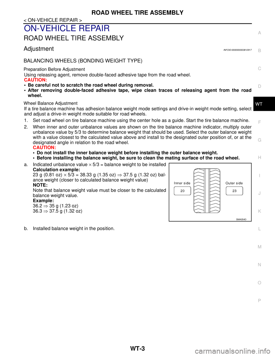
2. When inner and outer unbalance values are shown on the tire balance machine indicator, multiply outer
unbalance value by 5/3 to determine balance weight that should be used. Select the outer balance weight
with a value closest to the calculated value above and install to the designated outer position of, or at the
designated angle in relation to the road wheel.
CAUTION:
Do not install the inner balance weight before installing the outer balance weight.
Before installing the balance weight, be sure to clean the mating surface of the road wheel.
a. Indicated unbalance value × 5/3 = balance weight to be installed
Calculation example:
23 g (0.81 oz) × 5/3 = 38.33 g (1.35 oz) ⇒ 37.5 g (1.32 oz) bal-
ance weight (closer to calculated balance weight value)
NOTE:
Note that balance weight value must be closer to the calculated
balance weight value.
Example:
36.2 ⇒ 35 g (1.23 oz)
36.3 ⇒ 37.5 g (1.32 oz)
b. Installed balance weight in the position.
SMA054D
Page 5011 of 5121
WT-4
< ON-VEHICLE REPAIR >
ROAD WHEEL TIRE ASSEMBLY
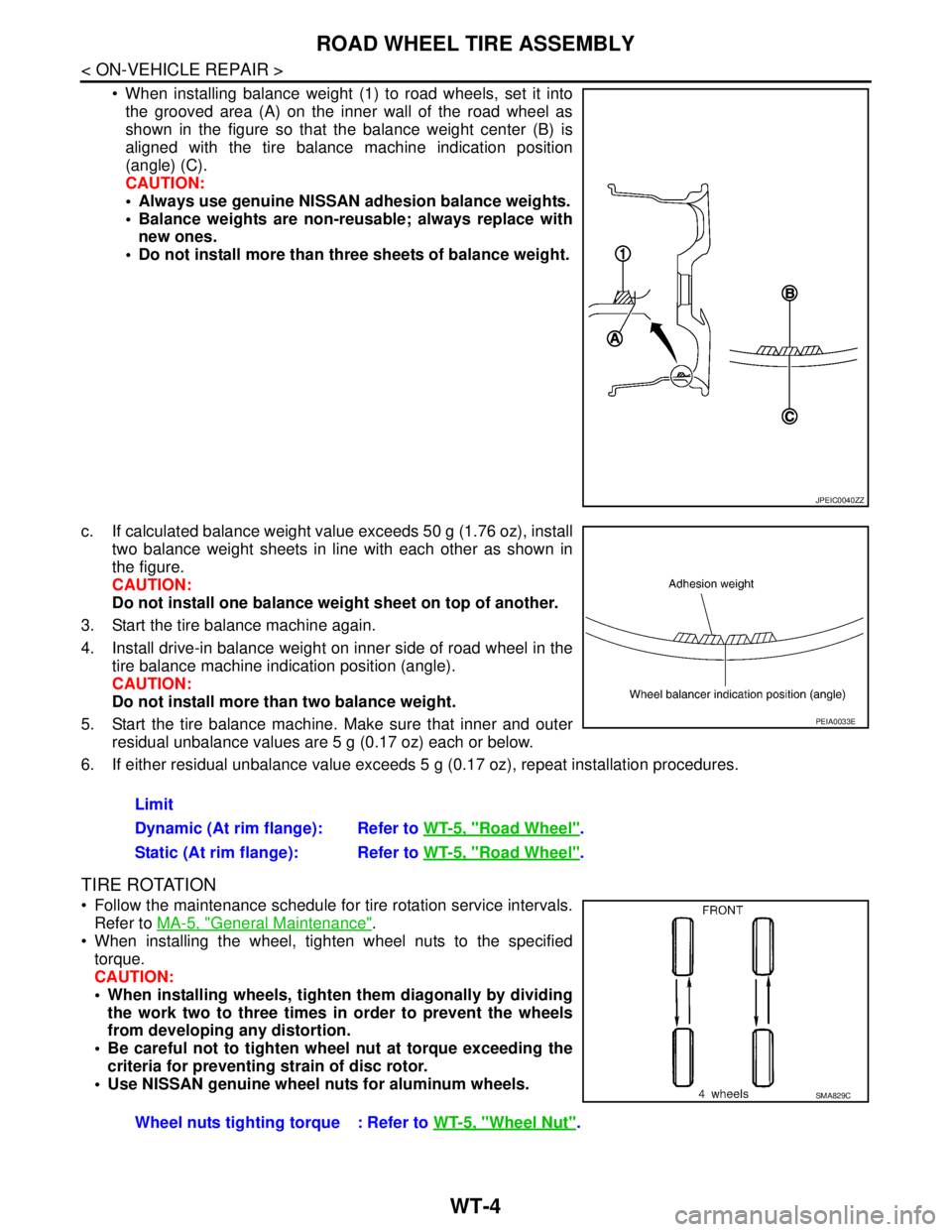
When installing balance weight (1) to road wheels, set it into
the grooved area (A) on the inner wall of the road wheel as
shown in the figure so that the balance weight center (B) is
aligned with the tire balance machine indication position
(angle) (C).
CAUTION:
Always use genuine NISSAN adhesion balance weights.
Balance weights are non-reusable; always replace with
new ones.
Do not install more than three sheets of balance weight.
c. If calculated balance weight value exceeds 50 g (1.76 oz), install
two balance weight sheets in line with each other as shown in
the figure.
CAUTION:
Do not install one balance weight sheet on top of another.
3. Start the tire balance machine again.
4. Install drive-in balance weight on inner side of road wheel in the
tire balance machine indication position (angle).
CAUTION:
Do not install more than two balance weight.
5. Start the tire balance machine. Make sure that inner and outer
residual unbalance values are 5 g (0.17 oz) each or below.
6. If either residual unbalance value exceeds 5 g (0.17 oz), repeat installation procedures.
TIRE ROTATION
Follow the maintenance schedule for tire rotation service intervals.
Refer to MA-5, "
General Maintenance".
When installing the wheel, tighten wheel nuts to the specified
torque.
CAUTION:
When installing wheels, tighten them diagonally by dividing
the work two to three times in order to prevent the wheels
from developing any distortion.
Be careful not to tighten wheel nut at torque exceeding the
criteria for preventing strain of disc rotor.
Use NISSAN genuine wheel nuts for aluminum wheels.
JPEIC0040ZZ
Limit
Dynamic (At rim flange): Refer to WT-5, "
Road Wheel".
Static (At rim flange): Refer to WT-5, "
Road Wheel".
PEIA0033E
Wheel nuts tighting torque : Refer to WT-5, "Wheel Nut".
SMA829C