trunk NISSAN TEANA 2008 Service Manual
[x] Cancel search | Manufacturer: NISSAN, Model Year: 2008, Model line: TEANA, Model: NISSAN TEANA 2008Pages: 5121, PDF Size: 69.03 MB
Page 85 of 5121

BCM (BODY CONTROL MODULE)
ADP-79
< COMPONENT DIAGNOSIS >
C
D
E
F
G
H
I
K
L
MA
B
ADP
N
O
P
DOOR SW-BKNOTE:
The item is indicated, but not monitored. Off
CDL LOCK SWOther than power door lock switch LOCK Off
Power door lock switch LOCK On
CDL UNLOCK SWOther than power door lock switch UNLOCK Off
Power door lock switch UNLOCK On
KEY CYL LK-SWNOTE:
The item is indicated, but not monitored. Off
KEY CYL UN-SWNOTE:
The item is indicated, but not monitored. Off
KEY CYL SW-TRNOTE:
The item is indicated, but not monitored. Off
HAZARD SWHazard switch is OFF Off
Hazard switch is ON On
REAR DEF SW
NOTE:
At model with BOSE au-
dio system this item is in-
dicated, but is not
monitored.Rear window defogger switch is OFF Off
Rear window defogger switch is ON On
TR CANCEL SWNOTE:
The item is indicated, but not monitored. Off
TR/BD OPEN SWTrunk lid opener switch OFF Off
While the trunk lid opener switch is turned ON On
TRNK/HAT MNTRTrunk lid closed Off
Trunk lid opened On
RKE-LOCKLOCK button of the key is not pressed Off
LOCK button of the key is pressed On
RKE-UNLOCKUNLOCK button of the key is not pressed Off
UNLOCK button of the key is pressed On
RKE-TR/BDTRUNK OPEN button of the key is not pressed Off
TRUNK OPEN button of the key is pressed On
RKE-PANICNOTE:
The item is indicated, but not monitored. Off
RKE-P/W OPENNOTE:
The item is indicated, but not monitored. Off
RKE-MODE CHGLOCK/UNLOCK button of the key is not pressed and held simulta-
neouslyOff
LOCK/UNLOCK button of the key is pressed and held simulta-
neouslyOn
OPTICAL SENSORBright outside of the vehicle Close to 5 V
Dark outside of the vehicle Close to 0 V
REQ SW -DRDriver door request switch is not pressed Off
Driver door request switch is pressed On
REQ SW -ASPassenger door request switch is not pressed Off
Passenger door request switch is pressed On
REQ SW -RRNOTE:
The item is indicated, but not monitored. Off Monitor Item Condition Value/Status
Page 86 of 5121

ADP-80
< COMPONENT DIAGNOSIS >
BCM (BODY CONTROL MODULE)
REQ SW -RRNOTE:
The item is indicated, but not monitored. Off
REQ SW -BD/TRTrunk lid opener request switch is not pressed Off
Trunk lid opener request switch is pressed On
PUSH SWPush-button ignition switch (push switch) is not pressed Off
Push-button ignition switch (push switch) is pressed On
IGN RLY2 -F/BIgnition switch in OFF or ACC position Off
Ignition switch in ON position On
CLUCH SWNOTE:
The item is indicated, but not monitored. Off
BRAKE SW 1The brake pedal is not depressed On
The brake pedal is depressed Off
DETE/CANCL SWSelector lever in P position Off
Selector lever in any position other than P On
SFT PN/N SWSelector lever in any position other than P and N Off
Selector lever in P or N position On
S/L -LOCKSteering is locked Off
Steering is unlocked On
S/L -UNLOCKSteering is unlocked Off
Steering is locked On
S/L RELAY-F/BIgnition switch in OFF or ACC position Off
Ignition switch in ON position On
UNLK SEN -DRDriver door is unlocked Off
Driver door is locked On
PUSH SW -IPDMPush-button ignition switch (push-switch) is not pressed Off
Push-button ignition switch (push-switch) is pressed On
IGN RLY1 -F/BIgnition switch in OFF or ACC position Off
Ignition switch in ON position On
DETE SW -IPDMSelector lever in P position Off
Selector lever in any position other than P On
SFT PN -IPDMSelector lever in any position other than P and N Off
Selector lever in P or N position On
SFT P -METSelector lever in any position other than P Off
Selector lever in P position On
SFT N -METSelector lever in any position other than N Off
Selector lever in N position On
ENGINE STATEEngine stopped Stop
While the engine stalls Stall
At engine cranking Crank
Engine running Run
S/L LOCK-IPDMSteering is locked Off
Steering is unlocked On
S/L UNLK-IPDMSteering is unlocked Off
Steering is locked On Monitor Item Condition Value/Status
Page 90 of 5121

ADP-84
< COMPONENT DIAGNOSIS >
BCM (BODY CONTROL MODULE)
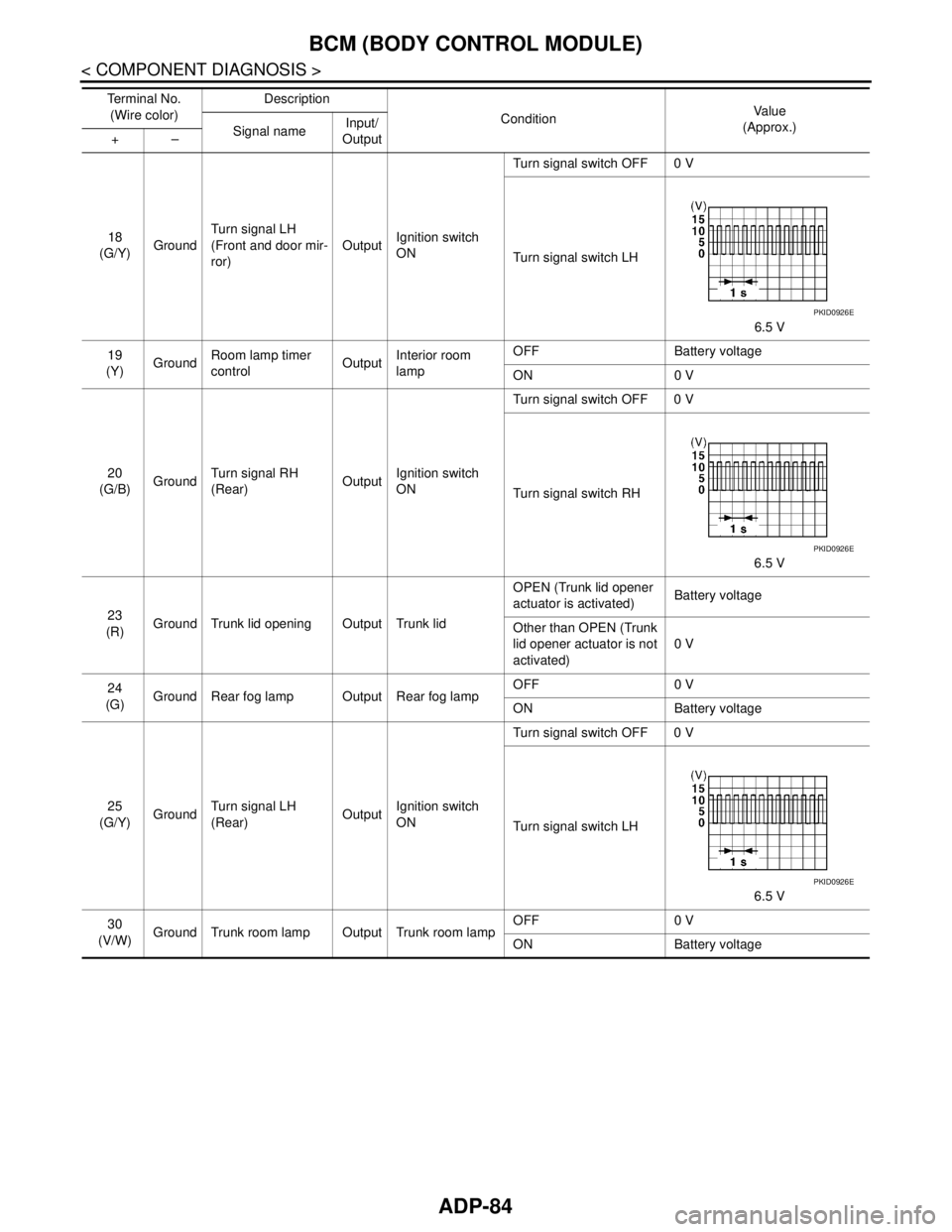
18
(G/Y)GroundTurn signal LH
(Front and door mir-
ror)OutputIgnition switch
ONTurn signal switch OFF 0 V
Turn signal switch LH
6.5 V
19
(Y)GroundRoom lamp timer
controlOutputInterior room
lampOFF Battery voltage
ON 0 V
20
(G/B)GroundTurn signal RH
(Rear)OutputIgnition switch
ONTurn signal switch OFF 0 V
Turn signal switch RH
6.5 V
23
(R)Ground Trunk lid opening Output Trunk lidOPEN (Trunk lid opener
actuator is activated)Battery voltage
Other than OPEN (Trunk
lid opener actuator is not
activated)0 V
24
(G)Ground Rear fog lamp Output Rear fog lampOFF 0 V
ON Battery voltage
25
(G/Y)GroundTurn signal LH
(Rear)OutputIgnition switch
ONTurn signal switch OFF 0 V
Turn signal switch LH
6.5 V
30
(V/W)Ground Trunk room lamp Output Trunk room lampOFF 0 V
ON Battery voltage Te r m i n a l N o .
(Wire color)Description
ConditionVa l u e
(Approx.)
Signal nameInput/
Output +–
PKID0926E
PKID0926E
PKID0926E
Page 91 of 5121

BCM (BODY CONTROL MODULE)
ADP-85
< COMPONENT DIAGNOSIS >
C
D
E
F
G
H
I
K
L
MA
B
ADP
N
O
P
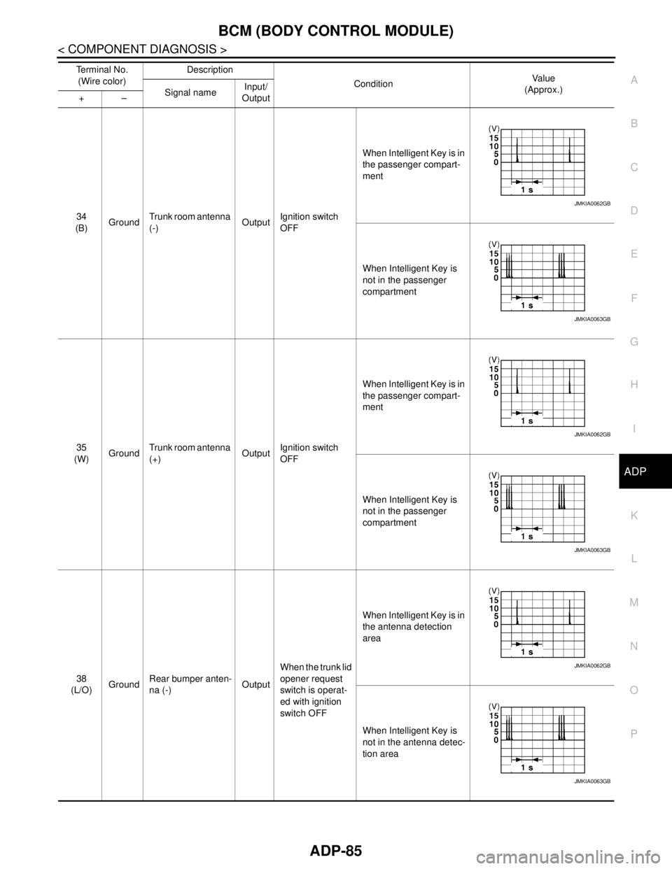
34
(B)GroundTrunk room antenna
(-)OutputIgnition switch
OFFWhen Intelligent Key is in
the passenger compart-
ment
When Intelligent Key is
not in the passenger
compartment
35
(W)GroundTrunk room antenna
(+)OutputIgnition switch
OFFWhen Intelligent Key is in
the passenger compart-
ment
When Intelligent Key is
not in the passenger
compartment
38
(L/O)GroundRear bumper anten-
na (-)OutputWhen the trunk lid
opener request
switch is operat-
ed with ignition
switch OFFWhen Intelligent Key is in
the antenna detection
area
When Intelligent Key is
not in the antenna detec-
tion area Te r m i n a l N o .
(Wire color)Description
ConditionVa l u e
(Approx.)
Signal nameInput/
Output +–
JMKIA0062GB
JMKIA0063GB
JMKIA0062GB
JMKIA0063GB
JMKIA0062GB
JMKIA0063GB
Page 92 of 5121

ADP-86
< COMPONENT DIAGNOSIS >
BCM (BODY CONTROL MODULE)
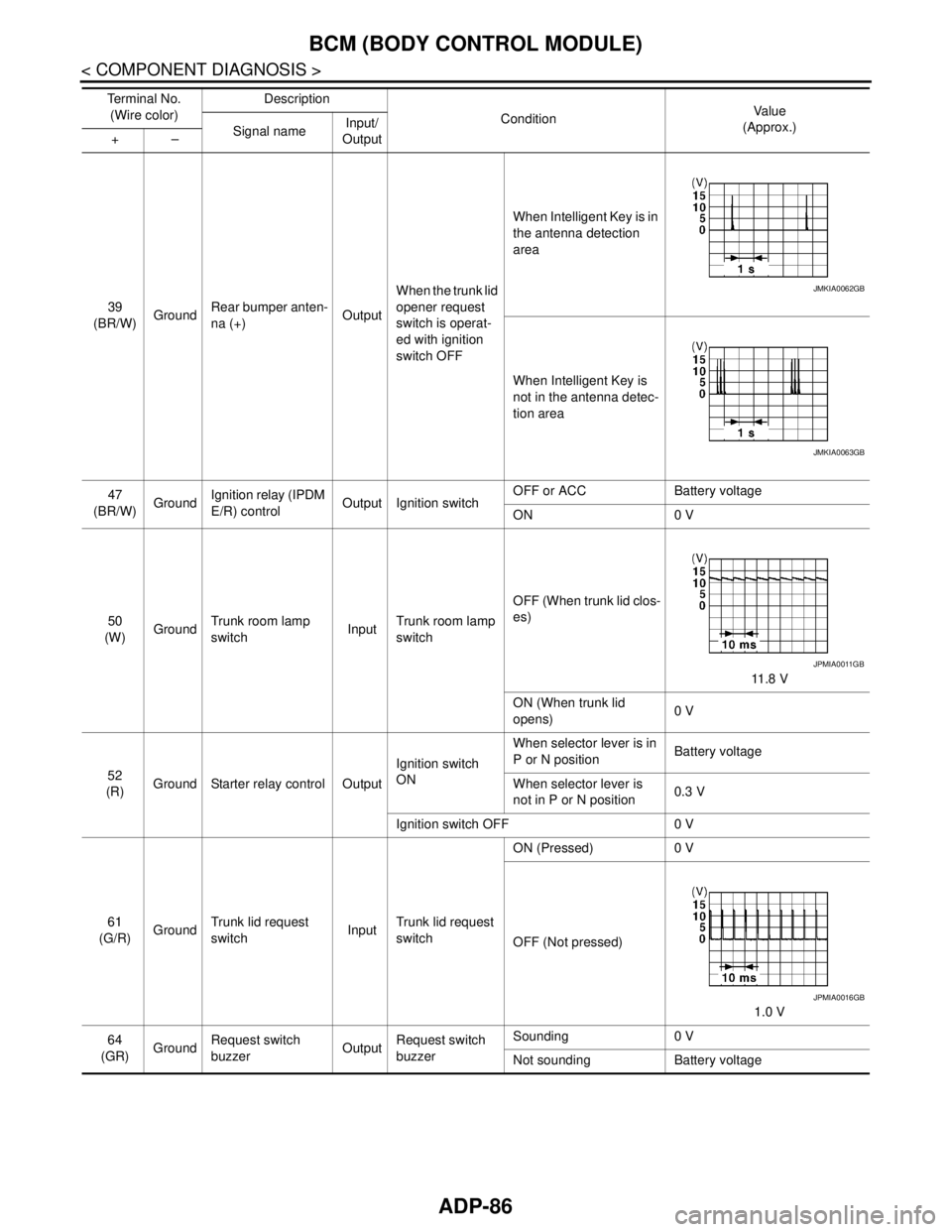
39
(BR/W)GroundRear bumper anten-
na (+)OutputWhen the trunk lid
opener request
switch is operat-
ed with ignition
switch OFFWhen Intelligent Key is in
the antenna detection
area
When Intelligent Key is
not in the antenna detec-
tion area
47
(BR/W)GroundIgnition relay (IPDM
E/R) controlOutput Ignition switchOFF or ACC Battery voltage
ON 0 V
50
(W)GroundTrunk room lamp
switchInputTrunk room lamp
switchOFF (When trunk lid clos-
es)
11 . 8 V
ON (When trunk lid
opens)0 V
52
(R)Ground Starter relay control OutputIgnition switch
ONWhen selector lever is in
P or N positionBattery voltage
When selector lever is
not in P or N position0.3 V
Ignition switch OFF 0 V
61
(G/R)GroundTrunk lid request
switchInputTrunk lid request
switchON (Pressed) 0 V
OFF (Not pressed)
1.0 V
64
(GR)GroundRequest switch
buzzerOutputRequest switch
buzzerSounding 0 V
Not sounding Battery voltage Te r m i n a l N o .
(Wire color)Description
ConditionVa l u e
(Approx.)
Signal nameInput/
Output +–
JMKIA0062GB
JMKIA0063GB
JPMIA0011GB
JPMIA0016GB
Page 93 of 5121

BCM (BODY CONTROL MODULE)
ADP-87
< COMPONENT DIAGNOSIS >
C
D
E
F
G
H
I
K
L
MA
B
ADP
N
O
P
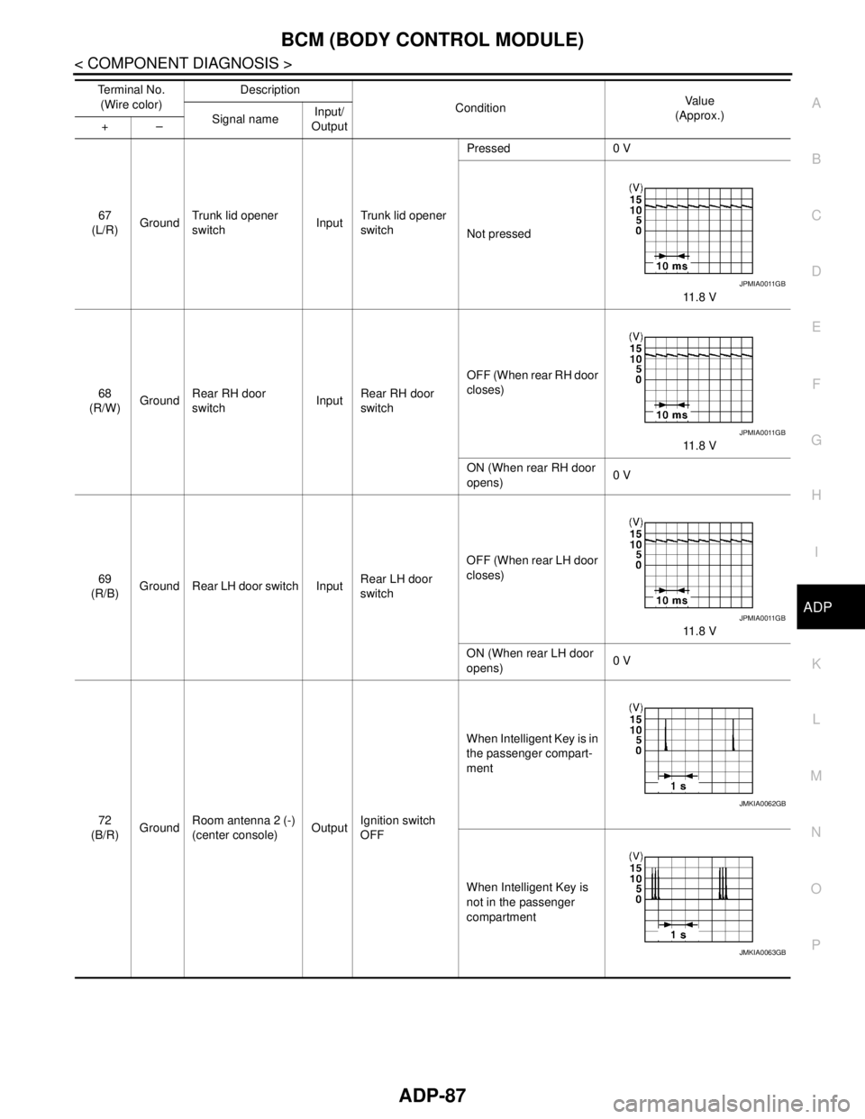
67
(L/R)GroundTrunk lid opener
switchInputTrunk lid opener
switchPressed 0 V
Not pressed
11.8 V
68
(R/W)GroundRear RH door
switchInputRear RH door
switchOFF (When rear RH door
closes)
11.8 V
ON (When rear RH door
opens)0 V
69
(R/B)Ground Rear LH door switch InputRear LH door
switchOFF (When rear LH door
closes)
11.8 V
ON (When rear LH door
opens)0 V
72
(B/R)GroundRoom antenna 2 (-)
(center console)OutputIgnition switch
OFFWhen Intelligent Key is in
the passenger compart-
ment
When Intelligent Key is
not in the passenger
compartment Te r m i n a l N o .
(Wire color)Description
ConditionVa l u e
(Approx.)
Signal nameInput/
Output +–
JPMIA0011GB
JPMIA0011GB
JPMIA0011GB
JMKIA0062GB
JMKIA0063GB
Page 194 of 5121
![NISSAN TEANA 2008 Service Manual AV-50
< FUNCTION DIAGNOSIS >[BASE AUDIO AND DISPLAY SYSTEM]
MULTI AV SYSTEM
Component Parts Location
INFOID:0000000003882701
1. Front squawker RH 2. Front squawker LH 3. Front door speaker LH
4. Rear NISSAN TEANA 2008 Service Manual AV-50
< FUNCTION DIAGNOSIS >[BASE AUDIO AND DISPLAY SYSTEM]
MULTI AV SYSTEM
Component Parts Location
INFOID:0000000003882701
1. Front squawker RH 2. Front squawker LH 3. Front door speaker LH
4. Rear](/img/5/57391/w960_57391-193.png)
AV-50
< FUNCTION DIAGNOSIS >[BASE AUDIO AND DISPLAY SYSTEM]
MULTI AV SYSTEM
Component Parts Location
INFOID:0000000003882701
1. Front squawker RH 2. Front squawker LH 3. Front door speaker LH
4. Rear door speaker LH 5. Rear control switch 6. Rear view camera
7. Camera control unit 8. Antenna amp. 9. Rear door speaker RH
10. Front door speaker RH 11. Steering angle sensor 12. Steering switch
13. AV control unit 14. Auxiliary input jacks 15. Preset switch
16. Multifunction switch 17. Display unit
A. Trunk room side RH B. Within rear pillar finisher RH C. Spiral cable part
D. In center console
JSNIA1433ZZ
Page 198 of 5121
![NISSAN TEANA 2008 Service Manual AV-54
< FUNCTION DIAGNOSIS >[BASE AUDIO AND DISPLAY SYSTEM]
AUDIO SYSTEM
Component Parts Location
INFOID:0000000003885180
1. Front squawker RH 2. Front squawker LH 3. Front door speaker LH
4. Rear doo NISSAN TEANA 2008 Service Manual AV-54
< FUNCTION DIAGNOSIS >[BASE AUDIO AND DISPLAY SYSTEM]
AUDIO SYSTEM
Component Parts Location
INFOID:0000000003885180
1. Front squawker RH 2. Front squawker LH 3. Front door speaker LH
4. Rear doo](/img/5/57391/w960_57391-197.png)
AV-54
< FUNCTION DIAGNOSIS >[BASE AUDIO AND DISPLAY SYSTEM]
AUDIO SYSTEM
Component Parts Location
INFOID:0000000003885180
1. Front squawker RH 2. Front squawker LH 3. Front door speaker LH
4. Rear door speaker LH 5. Rear control switch 6. Rear view camera
7. Camera control unit 8. Antenna amp. 9. Rear door speaker RH
10. Front door speaker RH 11. Steering angle sensor 12. Steering switch
13. AV control unit 14. Auxiliary input jacks 15. Preset switch
16. Multifunction switch 17. Display unit
A. Trunk room side RH B. Within rear pillar finisher RH C. Spiral cable part
D. In center console
JSNIA1433ZZ
Page 202 of 5121
![NISSAN TEANA 2008 Service Manual AV-58
< FUNCTION DIAGNOSIS >[BASE AUDIO AND DISPLAY SYSTEM]
REAR VIEW MONITOR SYSTEM
Component Parts Location
INFOID:0000000003885182
1. Front squawker RH 2. Front squawker LH 3. Front door speaker LH NISSAN TEANA 2008 Service Manual AV-58
< FUNCTION DIAGNOSIS >[BASE AUDIO AND DISPLAY SYSTEM]
REAR VIEW MONITOR SYSTEM
Component Parts Location
INFOID:0000000003885182
1. Front squawker RH 2. Front squawker LH 3. Front door speaker LH](/img/5/57391/w960_57391-201.png)
AV-58
< FUNCTION DIAGNOSIS >[BASE AUDIO AND DISPLAY SYSTEM]
REAR VIEW MONITOR SYSTEM
Component Parts Location
INFOID:0000000003885182
1. Front squawker RH 2. Front squawker LH 3. Front door speaker LH
4. Rear door speaker LH 5. Rear control switch 6. Rear view camera
7. Camera control unit 8. Antenna amp. 9. Rear door speaker RH
10. Front door speaker RH 11. Steering angle sensor 12. Steering switch
13. AV control unit 14. Auxiliary input jacks 15. Preset switch
16. Multifunction switch 17. Display unit
A. Trunk room side RH B. Within rear pillar finisher RH C. Spiral cable part
D. In center console
JSNIA1433ZZ
Page 325 of 5121
![NISSAN TEANA 2008 Service Manual AV
REAR VIEW CAMERA
AV-181
< ON-VEHICLE REPAIR >[BASE AUDIO AND DISPLAY SYSTEM]
C
D
E
F
G
H
I
J
K
L
MB A
O
P
REAR VIEW CAMERA
Exploded ViewINFOID:0000000003940176
DISASSEMBLY
Removal and InstallationI NISSAN TEANA 2008 Service Manual AV
REAR VIEW CAMERA
AV-181
< ON-VEHICLE REPAIR >[BASE AUDIO AND DISPLAY SYSTEM]
C
D
E
F
G
H
I
J
K
L
MB A
O
P
REAR VIEW CAMERA
Exploded ViewINFOID:0000000003940176
DISASSEMBLY
Removal and InstallationI](/img/5/57391/w960_57391-324.png)
AV
REAR VIEW CAMERA
AV-181
< ON-VEHICLE REPAIR >[BASE AUDIO AND DISPLAY SYSTEM]
C
D
E
F
G
H
I
J
K
L
MB A
O
P
REAR VIEW CAMERA
Exploded ViewINFOID:0000000003940176
DISASSEMBLY
Removal and InstallationINFOID:0000000003940177
REMOVAL
1. Remove trunk lid finisher inner. Refer to INT-59, "Removal and Installation".
2. Remove trunk lid finisher. Refer to EXT-38, "
Removal and Installation".
3. Remove rear view camera mounting clip, disconnect the rear view camera connector.
4. Remove rear view camera.
INSTALLATION
1. Installation is the reverse order of removal.
AdjustmentINFOID:0000000003970920
Adjust the guide line position if the guide line position is shifted after installing the rear view camera.
1. Draw lines on rearward area of the vehicle passing through the
following points: 200 mm (7.87 in) from both sides of the vehicle,
and 0.5 m (1.64 ft), 1.0 m (3.28 ft) from the rear end of the
bumper.
2. Set into “Adjust offset of rear view camera” mode of Confirma-
tion / Adjustment mode.
JPNIA1050ZZ
1. Rear view camera
2. Seal
Refer to GI-4, "
Components" for symbols in the figure.
SKIB3691E