Int NISSAN TEANA 2008 Service Manual
[x] Cancel search | Manufacturer: NISSAN, Model Year: 2008, Model line: TEANA, Model: NISSAN TEANA 2008Pages: 5121, PDF Size: 69.03 MB
Page 1 of 5121
MODEL J32 SERIES
© 2008 NISSAN INTERNATIONAL SA
Allrightsreserved.NopartofthisElectronicServiceManualmaybereproducedorstoredinaretrievalsystem,ortransmittedinanyform,or by any means, electronic, mechanical, photocopying, recording or otherwise, without the prior written permission of Nissan InternationalSA, Switzerland.
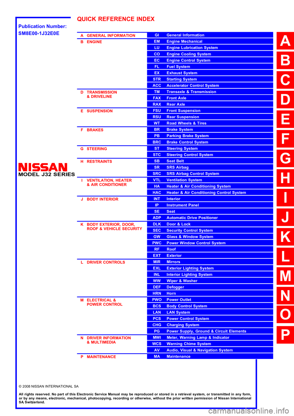
AGENERALINFORMATION
BENGINE
DTRANSMISSION&DRIVELINE
ESUSPENSION
FBRAKES
GSTEERING
HRESTRAINTS
IVENTILATION,HEATER&AIRCONDITIONER
JBODYINTERIOR
KBODYEXTERIOR,DOOR,ROOF&VEHICLESECURITY
LDRIVERCONTROLS
MELECTRICAL&POWERCONTROL
NDRIVERINFORMATION&MULTIMEDIA
PMAINTENANCE
GIGeneralInformation
EMEngineMechanical
LUEngineLubricationSystem
COEngineCoolingSystem
ECEngineControlSystem
FLFuelSystem
EXExhaustSystem
STRStartingSystem
ACCAcceleratorControlSystem
TMTransaxle &Transmission
FAXFrontAxle
RAXRearAxle
FSUFrontSuspension
RSURearSuspension
WTRoadWheels &Tires
BRBrakeSystem
PBParkingBrakeSystem
BRCBrakeControlSystem
STSteeringSystem
STCSteeringControlSystem
SBSeatBelt
SRSRSAirbag
SRCSRSAirbagControlSystem
VTLVentilationSystem
HAHeater &AirConditioningSystem
HACHeater &AirConditioningControlSystem
INTInterior
IPInstrumentPanel
SESeat
ADPAutomaticDrivePositioner
DLKDoor &Lock
SECSecurityControlSystem
GWGlass &WindowSystem
PWCPowerWindowControlSystem
RFRoof
EXTExterior
MIRMirrors
EXLExteriorLightingSystem
INLInteriorLightingSystem
WWWiper &Washer
DEFDefogger
HRNHorn
PWOPowerOutlet
BCSBodyControlSystem
LANLANSystem
PCSPowerControlSystem
CHGChargingSystem
PGPowerSupply,Ground&CircuitElements
MWIMeter,WarningLamp&Indicator
WCSWarningChimeSystem
AVAudio,Visual&NavigationSystem
MAMaintenance
QUICKREFERENCEINDEX
A
B
C
D
E
F
G
H
I
J
K
L
M
N
O
P
M
Publication Number:
SM8E00-1J32E0E
Page 2 of 5121

FOREWORD
This manual contains maintenance and repair procedures for the NISSAN
TEANA,modelJ32 series.
In order to assure your safety and the efficient functioning of the vehicle,
this manual should be read thoroughly. It is especially important that the
PRECAUTIONS in the GI section be completely understood before starting
any repair task.
All information in this manual is based on the latest product information
at the time of publication. The right is reserved to make changes in speci-
fications and methods at any time without notice.
IMPORTANT SAFETY NOTICE
The proper performance of service is essential for both the safety of the
technician and the efficient functioning of the vehicle.
The service methods in this Service Manual are described in such a man-
ner that the service may be performed safely and accurately.
Service varies with the procedures used, the skills of the technician and the
tools and parts available. Accordingly, anyone using service procedures,
tools or parts which are not specifically recommended by NISSAN must
first be completely satisfied that neither personal safety nor the vehicle's
safety will be jeopardized by the service method selected.
NISSANINTERNATIONAL SA
Service Engineering SectionParis, France
Page 3 of 5121

ACC-1
ENGINE
C
DE
F
G H
I
J
K L
M
SECTION ACC
A
ACC
N
O P
CONTENTS
ACCELERATOR CONTROL SYSTEM
PRECAUTION ................ ...............................2
PRECAUTIONS .............................................. .....2
Precaution for Supplemental Restraint System
(SRS) "AIR BAG" and "SEAT BELT PRE-TEN-
SIONER" ............................................................. ......
2
ON-VEHICLE REPAIR ..................................3
ACCELERATOR CONTROL SYSTEM ..............3
Exploded View ..................................................... .....3
Removal and Installation ..........................................3
Inspection .................................................................4
Page 4 of 5121

ACC-2
< PRECAUTION >
PRECAUTIONS
PRECAUTION
PRECAUTIONS
Precaution for Supplemental Restraint System (SRS) "AIR BAG" and "SEAT BELT
PRE-TENSIONER"
INFOID:0000000003801897
The Supplemental Restraint System such as “AIR BAG” and “SEAT BELT PRE-TENSIONER”, used along
with a front seat belt, helps to reduce the risk or severity of injury to the driver and front passenger for certain
types of collision. This system includes seat belt switch inputs and dual stage front air bag modules. The SRS
system uses the seat belt switches to determine the front air bag deployment, and may only deploy one front
air bag, depending on the severity of a collision and whether the front occupants are belted or unbelted.
Information necessary to service the system safely is included in the “SRS AIRBAG” and “SEAT BELT” of this
Service Manual.
WARNING:
• To avoid rendering the SRS inoperative, which could increase the risk of personal injury or death in
the event of a collision which would result in air bag inflation, all maintenance must be performed by
an authorized NISSAN/INFINITI dealer.
Improper maintenance, including incorrect removal and installation of the SRS, can lead to personal
injury caused by unintentional activation of the system. For removal of Spiral Cable and Air Bag
Module, see the “SRS AIRBAG”.
Do not use electrical test equipment on any circuit related to the SRS unless instructed to in this
Service Manual. SRS wiring harnesses can be identified by yellow and/or orange harnesses or har-
ness connectors.
Page 6 of 5121
ACC-4
< ON-VEHICLE REPAIR >
ACCELERATOR CONTROL SYSTEM
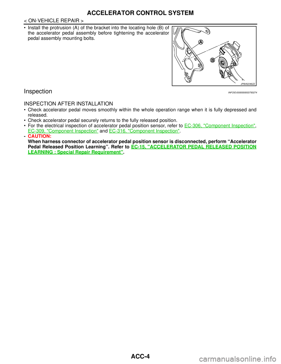
Install the protrusion (A) of the bracket into the locating hole (B) of
the accelerator pedal assembly before tightening the accelerator
pedal assembly mounting bolts.
InspectionINFOID:0000000003793274
INSPECTION AFTER INSTALLATION
Check accelerator pedal moves smoothly within the whole operation range when it is fully depressed and
released.
Check accelerator pedal securely returns to the fully released position.
For the electrical inspection of accelerator pedal position sensor, refer to EC-306, "
Component Inspection",
EC-309, "
Component Inspection" and EC-316, "Component Inspection".
-CAUTION:
When harness connector of accelerator pedal position sensor is disconnected, perform “Accelerator
Pedal Released Position Learning”. Refer to EC-15, "
ACCELERATOR PEDAL RELEASED POSITION
LEARNING : Special Repair Requirement".
JPBIA2246ZZ
Page 7 of 5121

ADP-1
BODY INTERIOR
C
D
E
F
G
H
I
K
L
M
SECTION ADP
A
B
ADP
N
O
P
CONTENTS
AUTOMATIC DRIVE POSITIONER
BASIC INSPECTION ....................................4
DIAGNOSIS AND REPAIR WORKFLOW ..........4
Work Flow .................................................................4
INSPECTION AND ADJUSTMENT .....................7
ADDITIONAL SERVICE WHEN REMOVING BAT-
TERY NEGATIVE TERMINAL .....................................
7
ADDITIONAL SERVICE WHEN REMOVING
BATTERY NEGATIVE TERMINAL : Description ......
7
ADDITIONAL SERVICE WHEN REMOVING
BATTERY NEGATIVE TERMINAL : Special Re-
pair Requirement .......................................................
7
ADDITIONAL SERVICE WHEN REPLACING
CONTROL UNIT ..........................................................
7
ADDITIONAL SERVICE WHEN REPLACING
CONTROL UNIT : Description ..................................
7
ADDITIONAL SERVICE WHEN REPLACING
CONTROL UNIT : Special Repair Requirement .......
7
SYSTEM INITIALIZATION ..........................................8
SYSTEM INITIALIZATION : Description ...................8
SYSTEM INITIALIZATION : Special Repair Re-
quirement ..................................................................
8
MEMORY STORING ....................................................8
MEMORY STORING : Description ............................8
MEMORY STORING : Special Repair Require-
ment ..........................................................................
9
SYSTEM SETTING ......................................................9
SYSTEM SETTING : Description ..............................9
SYSTEM SETTING : Special Repair Requirement
....
10
FUNCTION DIAGNOSIS ..............................12
AUTOMATIC DRIVE POSITIONER SYSTEM ....12
AUTOMATIC DRIVE POSITIONER SYSTEM ...........12
AUTOMATIC DRIVE POSITIONER SYSTEM :
System Diagram ......................................................
12
AUTOMATIC DRIVE POSITIONER SYSTEM :
System Description ..................................................
12
AUTOMATIC DRIVE POSITIONER SYSTEM :
Component Parts Location ......................................
14
AUTOMATIC DRIVE POSITIONER SYSTEM :
Component Description ..........................................
15
MANUAL FUNCTION ................................................16
MANUAL FUNCTION : System Diagram ................16
MANUAL FUNCTION : System Description ............16
MANUAL FUNCTION : Component Parts Loca-
tion ...........................................................................
17
MANUAL FUNCTION : Component Description .....18
MEMORY FUNCTION ................................................18
MEMORY FUNCTION : System Diagram ...............19
MEMORY FUNCTION : System Description ...........19
MEMORY FUNCTION : Component Parts Loca-
tion ...........................................................................
21
MEMORY FUNCTION : Component Description ....22
EXIT ASSIST FUNCTION ..........................................22
EXIT ASSIST FUNCTION : System Diagram ..........23
EXIT ASSIST FUNCTION : System Description .....23
EXIT ASSIST FUNCTION : Component Parts Lo-
cation .......................................................................
25
EXIT ASSIST FUNCTION :
Component Description ..........................................
26
ENTRY ASSIST FUNCTION ......................................26
ENTRY ASSIST FUNCTION : System Diagram .....27
ENTRY ASSIST FUNCTION : System Description
....
27
ENTRY ASSIST FUNCTION : Component Parts
Location ...................................................................
29
ENTRY ASSIST FUNCTION :
Component Description ..........................................
30
INTELLIGENT KEY INTERLOCK FUNCTION ..........30
Page 8 of 5121

ADP-2
INTELLIGENT KEY INTERLOCK FUNCTION :
System Diagram .....................................................
31
INTELLIGENT KEY INTERLOCK FUNCTION :
System Description .................................................
31
INTELLIGENT KEY INTERLOCK FUNCTION :
Component Parts Location .....................................
33
INTELLIGENT KEY INTERLOCK FUNCTION :
Component Description .........................................
34
DIAGNOSIS SYSTEM (DRIVER SEAT CON-
TROL UNIT) .......................................................
35
Diagnosis Description .............................................35
CONSULT-III Function ...........................................35
COMPONENT DIAGNOSIS ........................38
U1000 CAN COMM CIRCUIT ............................38
Description ..............................................................38
DTC Logic ...............................................................38
Diagnosis Procedure .............................................38
Special Repair Requirement ...................................38
U1010 CONTROL UNIT (CAN) .........................39
Description ..............................................................39
DTC Logic ...............................................................39
Diagnosis Procedure ..............................................39
B2130 EEPROM ................................................40
DTC Logic ...............................................................40
Diagnosis Procedure .............................................40
B2112 SLIDING MOTOR ...................................41
Description ..............................................................41
DTC Logic ...............................................................41
Diagnosis Procedure .............................................41
B2113 RECLINING MOTOR ..............................43
Description ..............................................................43
DTC Logic ...............................................................43
Diagnosis Procedure .............................................43
POWER SUPPLY AND GROUND CIRCUIT .....45
DRIVER SEAT CONTROL UNIT ..............................45
DRIVER SEAT CONTROL UNIT :
Diagnosis Procedure .............................................
45
SLIDING SWITCH ..............................................46
Description ..............................................................46
Component Function Check .................................46
Diagnosis Procedure .............................................46
Component Inspection ............................................47
RECLINING SWITCH ........................................48
Description ..............................................................48
Component Function Check .................................48
Diagnosis Procedure .............................................48
Component Inspection ............................................49
LIFTING SWITCH (FRONT) ..............................50
Description ..............................................................50
Component Function Check .................................50
Diagnosis Procedure ..............................................50
Component Inspection ............................................51
LIFTING SWITCH (REAR) ................................52
Description ..............................................................52
Component Function Check ..................................52
Diagnosis Procedure ..............................................52
Component Inspection ............................................53
SEAT MEMORY SWITCH .................................54
Description ..............................................................54
Component Function Check ..................................54
Diagnosis Procedure ..............................................54
Component Inspection ............................................55
POWER SEAT SWITCH GROUND CIRCUIT ...57
Diagnosis Procedure ..............................................57
FRONT DOOR SWITCH (DRIVER SIDE) .........58
Description ..............................................................58
Component Function Check ...................................58
Diagnosis Procedure ...............................................58
Component Inspection ............................................59
SLIDING SENSOR ............................................60
Description ..............................................................60
Component Function Check ..................................60
Diagnosis Procedure ..............................................60
RECLINING SENSOR .......................................62
Description ..............................................................62
Component Function Check ..................................62
Diagnosis Procedure ..............................................62
LIFTING SENSOR (FRONT) .............................64
Description ..............................................................64
Component Function Check ..................................64
Diagnosis Procedure ..............................................64
LIFTING SENSOR (REAR) ...............................66
Description ..............................................................66
Component Function Check ..................................66
Diagnosis Procedure ..............................................66
SLIDING MOTOR ..............................................68
Description ..............................................................68
Component Function Check ..................................68
Diagnosis Procedure ..............................................68
RECLINING MOTOR .........................................70
Description ..............................................................70
Component Function Check ..................................70
Diagnosis Procedure ..............................................70
LIFTING MOTOR (FRONT) ...............................72
Description ..............................................................72
Component Function Check ..................................72
Diagnosis Procedure ..............................................72
LIFTING MOTOR (REAR) .................................74
Description ..............................................................74
Component Function Check ..................................74
Page 9 of 5121

ADP-3
C
D
E
F
G
H
I
K
L
MA
B
ADP
N
O
P Diagnosis Procedure ..............................................
74
SEAT MEMORY INDICATOR ............................76
Description ..............................................................76
Component Function Check ..................................76
Diagnosis Procedure ..............................................76
Component Inspection ............................................77
BCM (BODY CONTROL MODULE) ...................78
Reference Value .....................................................78
Wiring Diagram - AUTOMATIC DRIVE POSI-
TIONER CONTROL SYSTEM - ............................
101
Fail-safe ................................................................107
DTC Inspection Priority Chart .............................109
DTC Index ............................................................110
ECU DIAGNOSIS .......................................112
DRIVER SEAT CONTROL UNIT ......................112
Reference Value ...................................................112
Wiring Diagram - AUTOMATIC DRIVE POSI-
TIONER CONTROL SYSTEM - ............................
117
Fail-safe ................................................................123
DTC Index ............................................................124
SYMPTOM DIAGNOSIS ............................125
MANUAL FUNCTION DOES NOT OPERATE ..125
ALL COMPONENTS ...............................................125
ALL COMPONENTS : Diagnosis Procedure .........125
SEAT SLIDING ........................................................125
SEAT SLIDING : Diagnosis Procedure .................125
SEAT RECLINING ...................................................126
SEAT RECLINING : Diagnosis Procedure ............126
SEAT LIFTING (FRONT) .........................................126
SEAT LIFTING (FRONT) : Diagnosis Procedure ..126
SEAT LIFTING (REAR) ...........................................127
SEAT LIFTING (REAR) : Diagnosis Procedure ....127
MEMORY FUNCTION DOES NOT OPERATE ..128
ALL COMPONENTS ...............................................128
ALL COMPONENTS : Diagnosis Procedure .........128
SEAT SLIDING ........................................................128
SEAT SLIDING : Diagnosis Procedure .................129
SEAT RECLINING ...................................................129
SEAT RECLINING : Diagnosis Procedure ............129
SEAT LIFTING (FRONT) .........................................129
SEAT LIFTING (FRONT) : Diagnosis Procedure ..129
SEAT LIFTING (REAR) ...........................................130
SEAT LIFTING (REAR) : Diagnosis Procedure .....130
MEMORY INDICATE DOES NOT OPERATE .131
Diagnosis Procedure .............................................131
ENTRY/EXIT ASSIST FUNCTION DOES NOT
OPERATE .......................................................
132
Diagnosis Procedure .............................................132
INTELLIGENT KEY INTERLOCK FUNCTION
DOES NOT OPERATE ....................................
133
Diagnosis Procedure .............................................133
NORMAL OPERATING CONDITION .............134
Description .............................................................134
PRECAUTION ............................................135
PRECAUTIONS ...............................................135
Precaution for Supplemental Restraint System
(SRS) "AIR BAG" and "SEAT BELT PRE-TEN-
SIONER" ...............................................................
135
ON-VEHICLE REPAIR ...............................136
DRIVER SEAT CONTROL UNIT ....................136
Exploded View .......................................................136
Removal and Installation .......................................136
SEAT MEMORY SWITCH ...............................137
Exploded View .......................................................137
Removal and Installation .......................................137
POWER SEAT SWITCH .................................138
Exploded View .......................................................138
Removal and Installation .......................................138
Page 11 of 5121
DIAGNOSIS AND REPAIR WORKFLOW
ADP-5
< BASIC INSPECTION >
C
D
E
F
G
H
I
K
L
MA
B
ADP
N
O
P
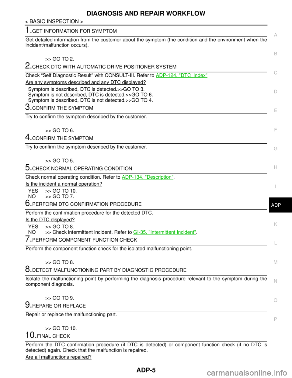
1.GET INFORMATION FOR SYMPTOM
Get detailed information from the customer about the symptom (the condition and the environment when the
incident/malfunction occurs).
>> GO TO 2.
2.CHECK DTC WITH AUTOMATIC DRIVE POSITIONER SYSTEM
Check “Self Diagnostic Result” with CONSULT-III. Refer to ADP-124, "
DTCIndex"
Are any symptoms described and any DTC displayed?
Symptom is described, DTC is detected.>>GO TO 3.
Symptom is not described, DTC is detected.>>GO TO 6.
Symptom is described, DTC is not detected.>>GO TO 4.
3.CONFIRM THE SYMPTOM
Try to confirm the symptom described by the customer.
>> GO TO 6.
4.CONFIRM THE SYMPTOM
Try to confirm the symptom described by the customer.
>> GO TO 5.
5.CHECK NORMAL OPERATING CONDITION
Check normal operating condition. Refer to ADP-134, "
Description".
Is the incident a normal operation?
YES >> GO TO 10.
NO >> GO TO 7.
6.PERFORM DTC CONFIRMATION PROCEDURE
Perform the confirmation procedure for the detected DTC.
Is the DTC displayed?
YES >> GO TO 8.
NO >> Check intermittent incident. Refer to GI-35, "
Intermittent Incident".
7.PERFORM COMPONENT FUNCTION CHECK
Perform the component function check for the isolated malfunctioning point.
>> GO TO 8.
8.DETECT MALFUNCTIONING PART BY DIAGNOSTIC PROCEDURE
Isolate the malfunctioning point by performing the diagnosis procedure relevant to the symptom during the
component diagnosis.
>> GO TO 9.
9.REPARE OR REPLACE
Repair or replace the malfunctioning part.
>> GO TO 10.
10.FINAL CHECK
Perform the DTC confirmation procedure (if DTC is detected) or component function check (if no DTC is
detected) again. Check that the malfunction is repaired.
Are all malfunctions repaired?
Page 13 of 5121
INSPECTION AND ADJUSTMENT
ADP-7
< BASIC INSPECTION >
C
D
E
F
G
H
I
K
L
MA
B
ADP
N
O
P
INSPECTION AND ADJUSTMENT
ADDITIONAL SERVICE WHEN REMOVING BATTERY NEGATIVE TERMINAL
ADDITIONAL SERVICE WHEN REMOVING BATTERY NEGATIVE TERMINAL : De-
scription
INFOID:0000000003759058
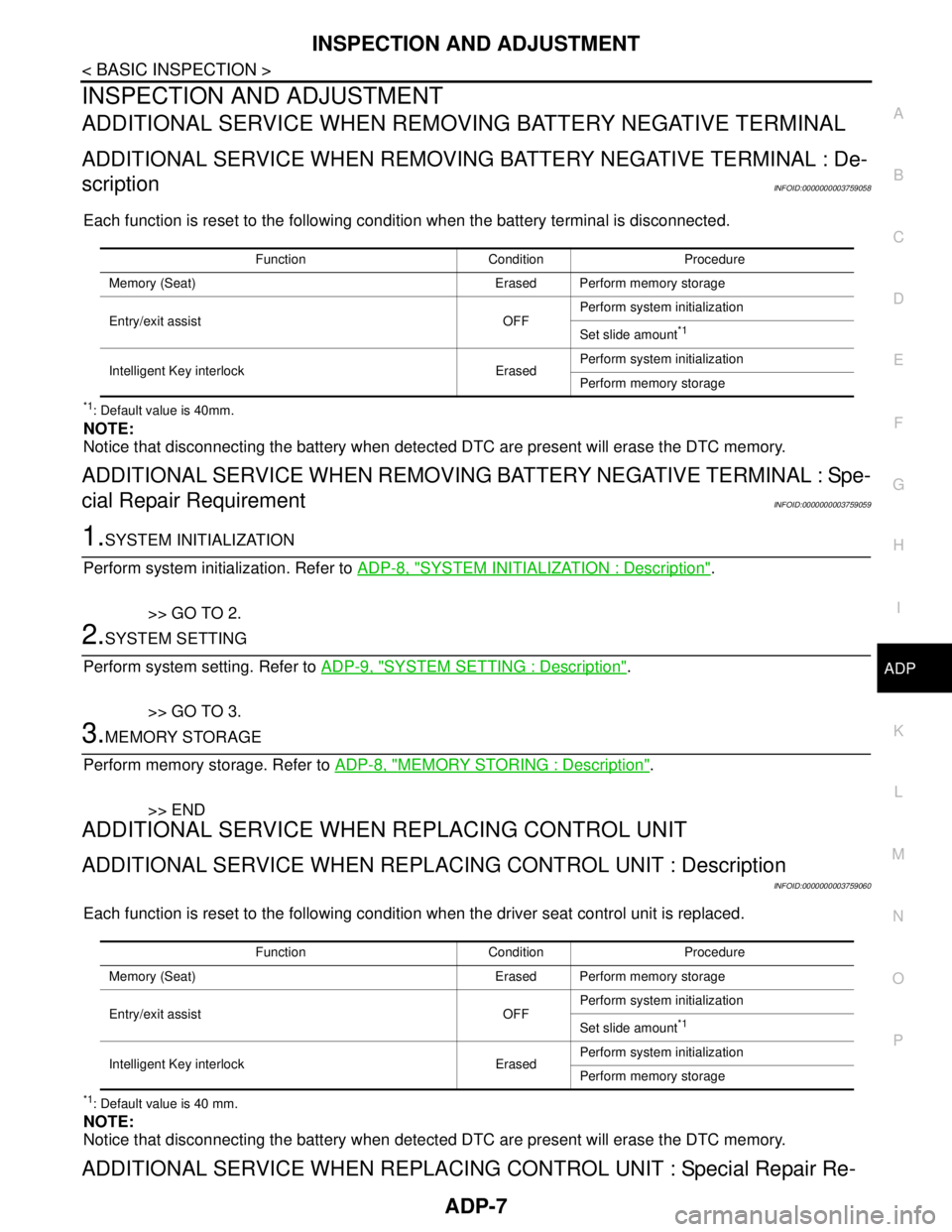
Each function is reset to the following condition when the battery terminal is disconnected.
*1: Default value is 40mm.
NOTE:
Notice that disconnecting the battery when detected DTC are present will erase the DTC memory.
ADDITIONAL SERVICE WHEN REMOVING BATTERY NEGATIVE TERMINAL : Spe-
cial Repair Requirement
INFOID:0000000003759059
1.SYSTEM INITIALIZATION
Perform system initialization. Refer to ADP-8, "
SYSTEM INITIALIZATION : Description".
>> GO TO 2.
2.SYSTEM SETTING
Perform system setting. Refer to ADP-9, "
SYSTEM SETTING : Description".
>> GO TO 3.
3.MEMORY STORAGE
Perform memory storage. Refer to ADP-8, "
MEMORY STORING : Description".
>> END
ADDITIONAL SERVICE WHEN REPLACING CONTROL UNIT
ADDITIONAL SERVICE WHEN REPLACING CONTROL UNIT : Description
INFOID:0000000003759060
Each function is reset to the following condition when the driver seat control unit is replaced.
*1: Default value is 40 mm.
NOTE:
Notice that disconnecting the battery when detected DTC are present will erase the DTC memory.
ADDITIONAL SERVICE WHEN REPLACING CONTROL UNIT : Special Repair Re-
Function Condition Procedure
Memory (Seat) Erased Perform memory storage
Entry/exit assist OFFPerform system initialization
Set slide amount
*1
Intelligent Key interlock ErasedPerform system initialization
Perform memory storage
Function Condition Procedure
Memory (Seat) Erased Perform memory storage
Entry/exit assist OFFPerform system initialization
Set slide amount
*1
Intelligent Key interlock ErasedPerform system initialization
Perform memory storage