Int NISSAN TEANA 2008 User Guide
[x] Cancel search | Manufacturer: NISSAN, Model Year: 2008, Model line: TEANA, Model: NISSAN TEANA 2008Pages: 5121, PDF Size: 69.03 MB
Page 14 of 5121
ADP-8
< BASIC INSPECTION >
INSPECTION AND ADJUSTMENT
quirement
INFOID:0000000003759061
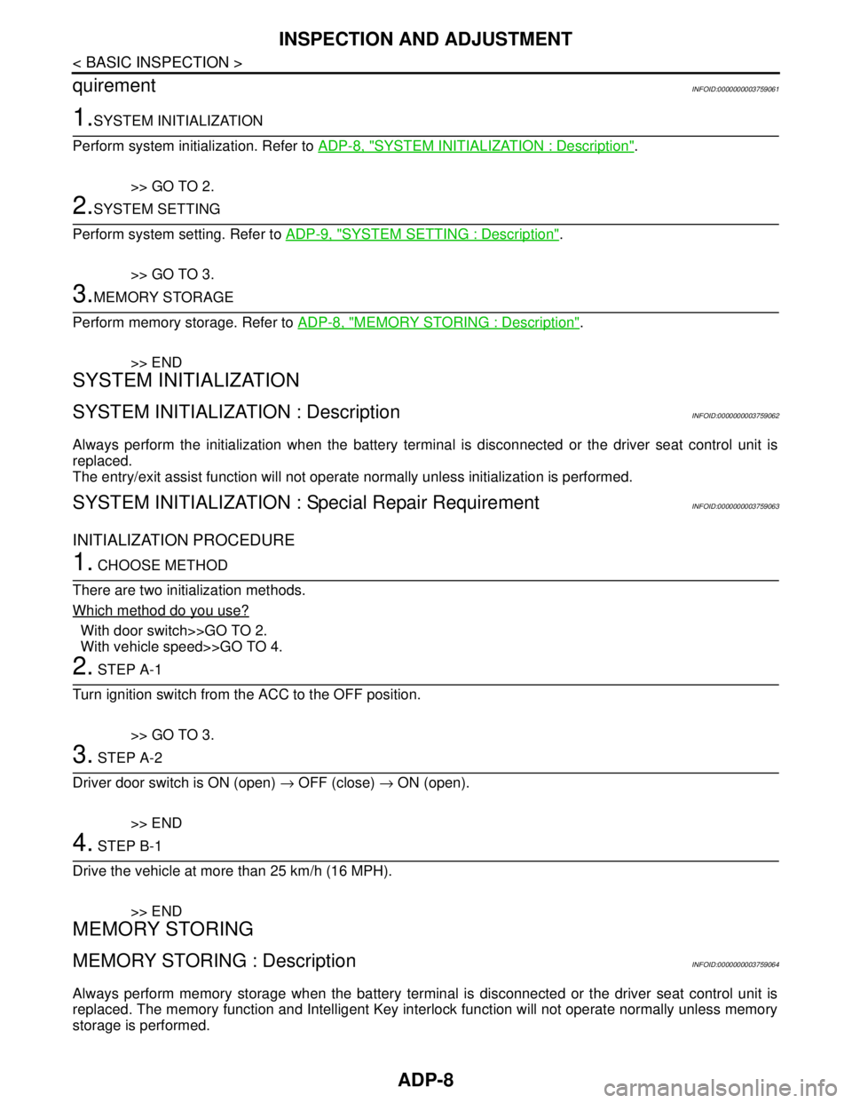
1.SYSTEM INITIALIZATION
Perform system initialization. Refer to ADP-8, "
SYSTEM INITIALIZATION : Description".
>> GO TO 2.
2.SYSTEM SETTING
Perform system setting. Refer to ADP-9, "
SYSTEM SETTING : Description".
>> GO TO 3.
3.MEMORY STORAGE
Perform memory storage. Refer to ADP-8, "
MEMORY STORING : Description".
>> END
SYSTEM INITIALIZATION
SYSTEM INITIALIZATION : DescriptionINFOID:0000000003759062
Always perform the initialization when the battery terminal is disconnected or the driver seat control unit is
replaced.
The entry/exit assist function will not operate normally unless initialization is performed.
SYSTEM INITIALIZATION : Special Repair RequirementINFOID:0000000003759063
INITIALIZATION PROCEDURE
1. CHOOSE METHOD
There are two initialization methods.
Which method do you use?
With door switch>>GO TO 2.
With vehicle speed>>GO TO 4.
2. STEP A-1
Turn ignition switch from the ACC to the OFF position.
>> GO TO 3.
3. STEP A-2
Driver door switch is ON (open) → OFF (close) → ON (open).
>> END
4. STEP B-1
Drive the vehicle at more than 25 km/h (16 MPH).
>> END
MEMORY STORING
MEMORY STORING : DescriptionINFOID:0000000003759064
Always perform memory storage when the battery terminal is disconnected or the driver seat control unit is
replaced. The memory function and Intelligent Key interlock function will not operate normally unless memory
storage is performed.
Page 15 of 5121
INSPECTION AND ADJUSTMENT
ADP-9
< BASIC INSPECTION >
C
D
E
F
G
H
I
K
L
MA
B
ADP
N
O
P
MEMORY STORING : Special Repair RequirementINFOID:0000000003759065
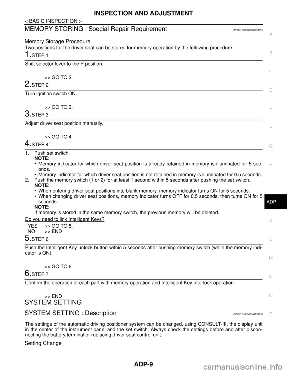
Memory Storage Procedure
Two positions for the driver seat can be stored for memory operation by the following procedure.
1.STEP 1
Shift selector lever to the P position.
>> GO TO 2.
2.STEP 2
Turn ignition switch ON.
>> GO TO 3.
3.STEP 3
Adjust driver seat position manually.
>> GO TO 4.
4.STEP 4
1. Push set switch.
NOTE:
Memory indicator for which driver seat position is already retained in memory is illuminated for 5 sec-
onds.
Memory indicator for which driver seat position is not retained in memory is illuminated for 0.5 seconds.
2. Push the memory switch (1 or 2) for at least 1 second within 5 seconds after pushing the set switch.
NOTE:
When entering driver seat positions into blank memory, memory indicator turns ON for 5 seconds.
When changing driver seat positions, memory indicator turns OFF for 0.5 seconds, then turns ON for 5
seconds.
NOTE:
If memory is stored in the same memory switch, the previous memory will be deleted.
Do you need to link Intelligent Keys?
YES >> GO TO 5.
NO >> END
5.STEP 6
Push the Intelligent Key unlock button within 5 seconds after pushing memory switch (while the memory indi-
cator is ON).
>> GO TO 6.
6.STEP 7
Confirm the operation of each part with memory operation and Intelligent Key interlock operation.
>> END
SYSTEM SETTING
SYSTEM SETTING : DescriptionINFOID:0000000003759066
The settings of the automatic driving positioner system can be changed, using CONSULT-III, the display unit
in the center of the instrument panel and the set switch. Always check the settings before and after discon-
necting the battery terminal or replacing driver seat control unit.
Setting Change
Page 18 of 5121
ADP-12
< FUNCTION DIAGNOSIS >
AUTOMATIC DRIVE POSITIONER SYSTEM
FUNCTION DIAGNOSIS
AUTOMATIC DRIVE POSITIONER SYSTEM
AUTOMATIC DRIVE POSITIONER SYSTEM
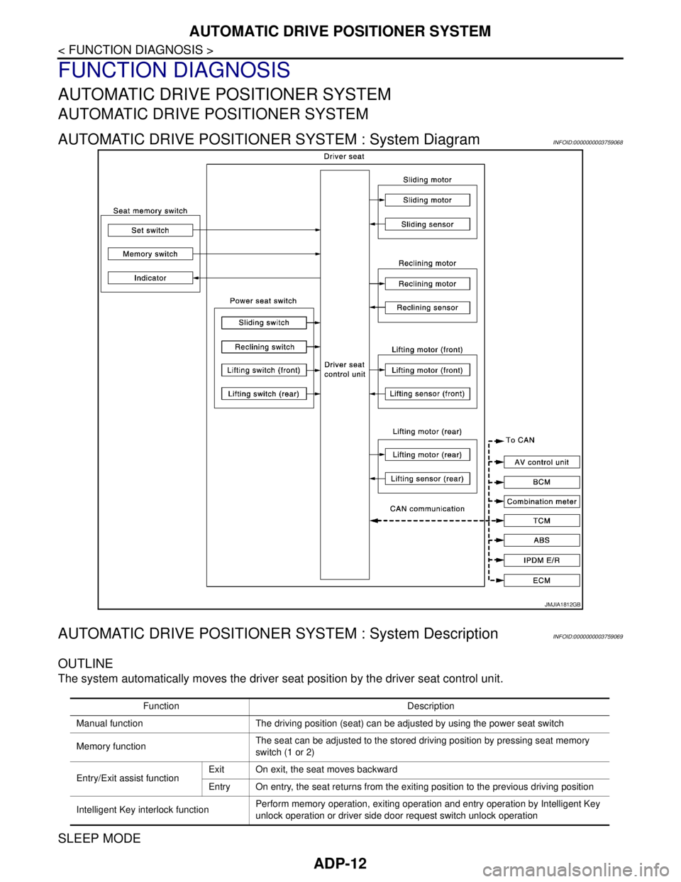
AUTOMATIC DRIVE POSITIONER SYSTEM : System DiagramINFOID:0000000003759068
AUTOMATIC DRIVE POSITIONER SYSTEM : System DescriptionINFOID:0000000003759069
OUTLINE
The system automatically moves the driver seat position by the driver seat control unit.
SLEEP MODE
JMJIA1812GB
Function Description
Manual function The driving position (seat) can be adjusted by using the power seat switch
Memory functionThe seat can be adjusted to the stored driving position by pressing seat memory
switch (1 or 2)
Entry/Exit assist functionExit On exit, the seat moves backward
Entry On entry, the seat returns from the exiting position to the previous driving position
Intelligent Key interlock functionPerform memory operation, exiting operation and entry operation by Intelligent Key
unlock operation or driver side door request switch unlock operation
Page 21 of 5121

AUTOMATIC DRIVE POSITIONER SYSTEM
ADP-15
< FUNCTION DIAGNOSIS >
C
D
E
F
G
H
I
K
L
MA
B
ADP
N
O
P
AUTOMATIC DRIVE POSITIONER SYSTEM : Component DescriptionINFOID:0000000003759071
CONTROL UNITS
INPUT PARTS
Switches
Sensors
OUTPUT PARTS
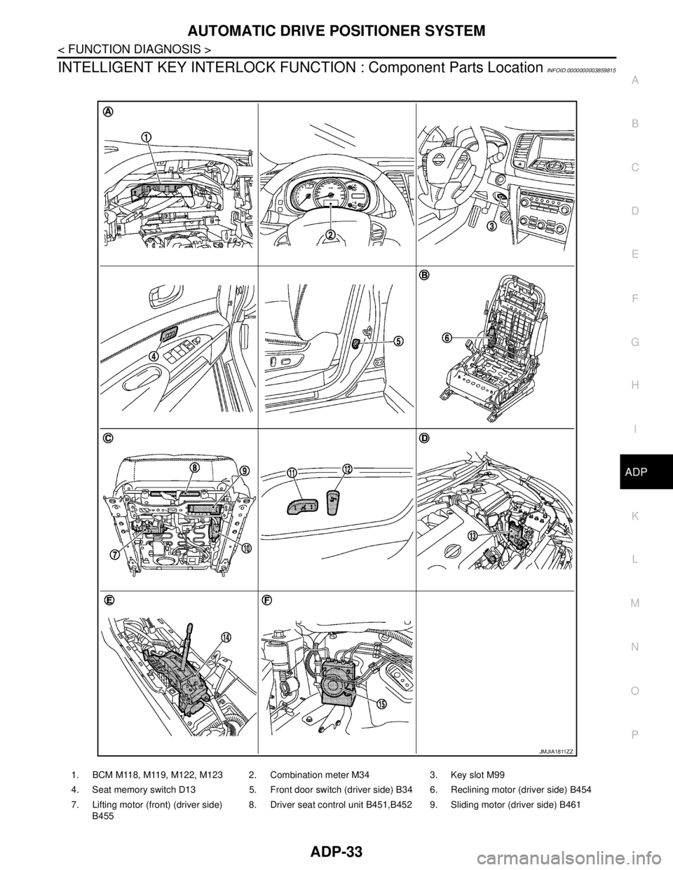
10. Lifting motor (rear) (driver side) B456 11. Power seat switch (driver side) B459
(sliding, lifting switch)12. Power seat switch (driver side) B459
(reclining switch)
13. TCM (transmission control module)
F2314. Control device (detention switch)
M5715. ABS actuator and electric unit (con-
trol unit) E36
A. Behind the combination meter B. View with seat cushion and seatback
pad removedC. Back side of the seat cushion
D. Engine room (LH) E. View with the center console assem-
bly removedF. Engine room (RH)
Item Function
Driver seat control unit Main unit of automatic drive positioner system
Connected to the CAN
BCMTransmits the following status to the driver seat control unit via CAN communication
Driver door: OPEN/CLOSE
Ignition switch position: ACC/ON
Door lock: UNLOCK (with Intelligent Key or driver side door request switch oper-
ation)
Key ID
Key switch: Insert/Pull out Intelligent Key
Starter: CRANKING/OTHER
Steering lock unit status: Lock/Unlock
Handle position
Combination meter / ABS actuator and
electric unit (control unit)Transmits the vehicle speed signal to the driver seat control unit via CAN commu-
nication
AV control unit The setting change of auto drive positioner system can be performed on the display
TCMTransmits the shift position signal (P range) to the driver seat control unit via CAN
communication
Item Function
Key slot The key switch is installed to detect the key inserted/removed status
Front door switch (driver side) Detects front door (driver side) open/close status
Control device (detention switch) Detects the P range position of selector lever
Set switch The registration and system setting can be performed with its operation
Memory switch 1/2 The registration and operation can be performed with its operation
Power seat switchThe following switches are installed
Reclining switch
Lifting switch (front)
Lifting switch (rear)
Sliding switch
Item Function
Lifting sensor (front) Detects the up/down position of seat lifting (front)
Lifting sensor (rear) Detects the up/down position of seat lifting (rear)
Reclining sensor Detects the tilt of seatback
Sliding sensor Detects the front/rear position of seat
Page 29 of 5121

AUTOMATIC DRIVE POSITIONER SYSTEM
ADP-23
< FUNCTION DIAGNOSIS >
C
D
E
F
G
H
I
K
L
MA
B
ADP
N
O
P
EXIT ASSIST FUNCTION : System DiagramINFOID:0000000003759080
EXIT ASSIST FUNCTION : System DescriptionINFOID:0000000003759081
OUTLINE
When opening the driver door while the operation condition is satisfied, the seat moves backward 40 mm
(1.57 in) from normal sitting position.
The seat slide amount operation at entry/exit operation can be changed.
NOTE:
This function is set to ON before delivery (initial setting).
Further information for the system setting procedure. Refer to ADP-8, "
SYSTEM INITIALIZATION : Descrip-
tion".
OPERATION PROCEDURE
1. Open the driver door with ignition switch in the OFF position.(Intelligent Key is not inserted into key slot)
2. Driver seat moves to the exiting position.
OPERATION CONDITION
Satisfy all of the following items. The exit assist function is not performed if any of these items are not satisfied.
JMJIA1816GB
Item Request status
Ignition positionOFF
System setting [Entry/exit assist function (seat)] ON
InitializationDone
Key switchOFF
(Intelligent Key is not inserted into key slot)
Switch inputs
Power seat switch
Set switch
Memory switchOFF
(Not operated)
Selector leverP position
BCMHandle position
Page 36 of 5121

ADP-30
< FUNCTION DIAGNOSIS >
AUTOMATIC DRIVE POSITIONER SYSTEM
ENTRY ASSIST FUNCTION : Component Description
INFOID:0000000003759087
CONTROL UNITS
INPUT PARTS
Sensors
OUTPUT PARTS
INTELLIGENT KEY INTERLOCK FUNCTION
10. Lifting motor (rear) (driver side) B45611. Power seat switch (driver side) B459
(sliding, lifting switch)12. Power seat switch (driver side) B459
(reclining switch)
13. TCM (transmission control module)
F2314. Control device (detention switch)
M5715. ABS actuator and electric unit (con-
trol unit) E36
A. Behind the combination meter B. View with seat cushion and seatback
pad removedC. Back side of the seat cushion
D. Engine room (LH) E. View with the center console assem-
bly removedF. Engine room (RH)
Item Function
Driver seat control unitOperates the seat sliding motor for a certain amount depending on the ignition sig-
nal and door switch signal (driver side) from BCM
BCMRecognizes the following status and transmits it to the driver seat control unit via
CAN communication
Ignition switch position: ACC/ON
Item Function
Sliding sensor Detect the front/rear position of seat
Item Function
Sliding motor Slides the seat frontward/rearward
Page 37 of 5121
AUTOMATIC DRIVE POSITIONER SYSTEM
ADP-31
< FUNCTION DIAGNOSIS >
C
D
E
F
G
H
I
K
L
MA
B
ADP
N
O
P
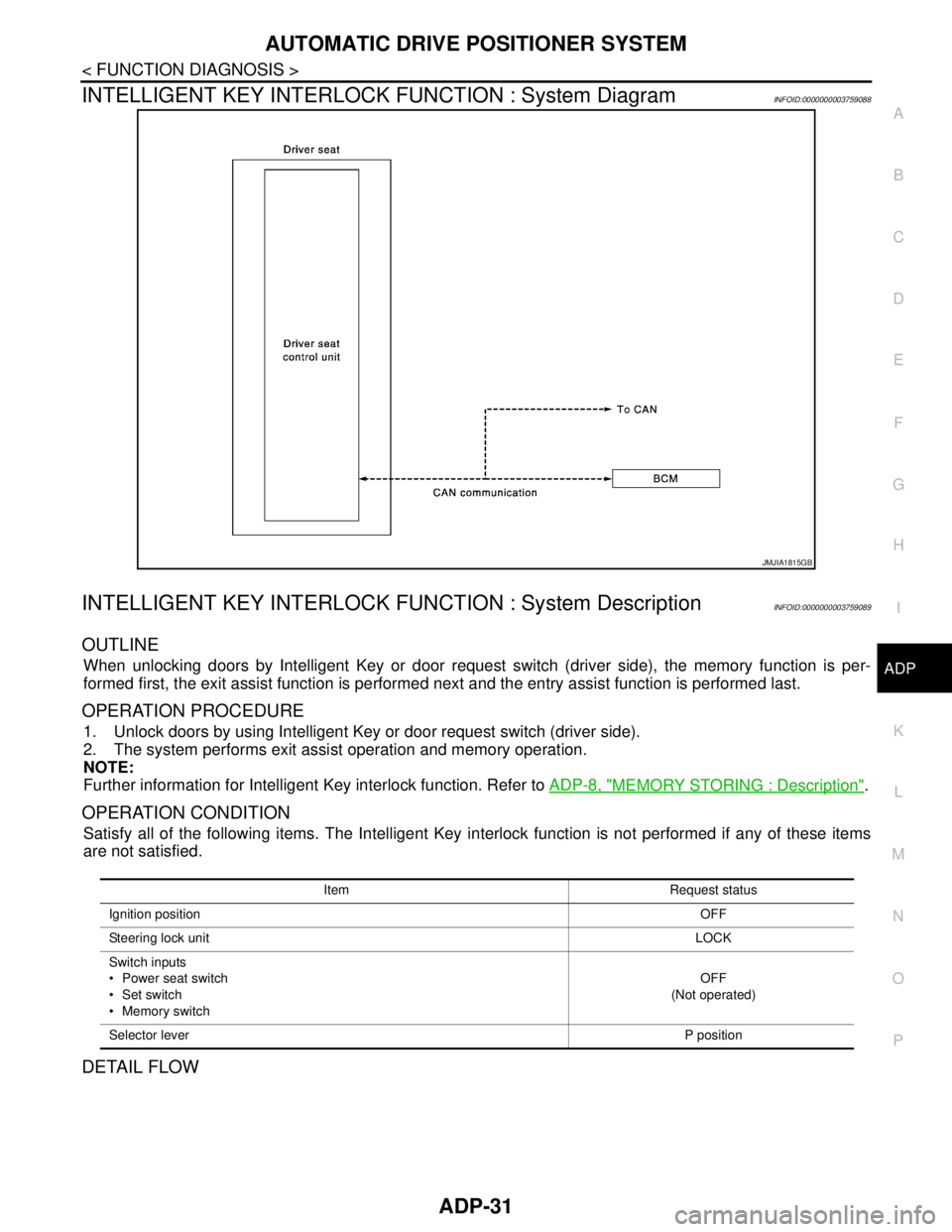
INTELLIGENT KEY INTERLOCK FUNCTION : System DiagramINFOID:0000000003759088
INTELLIGENT KEY INTERLOCK FUNCTION : System DescriptionINFOID:0000000003759089
OUTLINE
When unlocking doors by Intelligent Key or door request switch (driver side), the memory function is per-
formed first, the exit assist function is performed next and the entry assist function is performed last.
OPERATION PROCEDURE
1. Unlock doors by using Intelligent Key or door request switch (driver side).
2. The system performs exit assist operation and memory operation.
NOTE:
Further information for Intelligent Key interlock function. Refer to ADP-8, "
MEMORY STORING : Description".
OPERATION CONDITION
Satisfy all of the following items. The Intelligent Key interlock function is not performed if any of these items
are not satisfied.
DETAIL FLOW
JMJIA1815GB
Item Request status
Ignition positionOFF
Steering lock unitLOCK
Switch inputs
Power seat switch
Set switch
Memory switchOFF
(Not operated)
Selector leverP position
Page 38 of 5121

ADP-32
< FUNCTION DIAGNOSIS >
AUTOMATIC DRIVE POSITIONER SYSTEM
Order Input Output Control unit condition
1 Door unlock signal
(CAN)
Key ID signal (CAN)—Driver seat control unit receives the door unlock signal and the key
ID signal from BCM when unlocking the door with Intelligent Key or
driver side door request switch
2 — — Driver seat control unit performs the memory function
3 — — Driver seat control unit performs the exit assist function
4 — — Driver seat control unit performs the entry assist function
Page 39 of 5121
AUTOMATIC DRIVE POSITIONER SYSTEM
ADP-33
< FUNCTION DIAGNOSIS >
C
D
E
F
G
H
I
K
L
MA
B
ADP
N
O
P
INTELLIGENT KEY INTERLOCK FUNCTION : Component Parts LocationINFOID:0000000003859815
1. BCM M118, M119, M122, M123 2. Combination meter M34 3. Key slot M99
4. Seat memory switch D13 5. Front door switch (driver side) B34 6. Reclining motor (driver side) B454
7. Lifting motor (front) (driver side)
B4558. Driver seat control unit B451,B4529.Sliding motor (driver side) B461
JMJIA1811ZZ
Page 40 of 5121

ADP-34
< FUNCTION DIAGNOSIS >
AUTOMATIC DRIVE POSITIONER SYSTEM
INTELLIGENT KEY INTERLOCK FUNCTION : Component Description
INFOID:0000000003759091
CONTROL UNITS
10. Lifting motor (rear) (driver side) B45611. Power seat switch (driver side) B459
(sliding, lifting switch)12. Power seat switch (driver side) B459
(reclining switch)
13. TCM (transmission control module)
F2314. Control device (detention switch)
M5715. ABS actuator and electric unit (con-
trol unit) E36
A. Behind the combination meter B. View with seat cushion and seatback
pad removedC. Back side of the seat cushion
D. Engine room (LH) E. View with the center console assem-
bly removedF. Engine room (RH)
Item Function
Driver seat control unitPerforms memory function and entry/exit assist function after receiving the door un-
lock signal from BCM
BCMRecognizes the following status and transmits it to the driver seat control unit via
CAN communication
Door lock: UNLOCK
(with Intelligent Key or driver side door request switch)
Key ID signal
Ignition switch signal