dlk NISSAN TEANA 2008 Service Manual
[x] Cancel search | Manufacturer: NISSAN, Model Year: 2008, Model line: TEANA, Model: NISSAN TEANA 2008Pages: 5121, PDF Size: 69.03 MB
Page 1 of 5121
MODEL J32 SERIES
© 2008 NISSAN INTERNATIONAL SA
Allrightsreserved.NopartofthisElectronicServiceManualmaybereproducedorstoredinaretrievalsystem,ortransmittedinanyform,or by any means, electronic, mechanical, photocopying, recording or otherwise, without the prior written permission of Nissan InternationalSA, Switzerland.
AGENERALINFORMATION
BENGINE
DTRANSMISSION&DRIVELINE
ESUSPENSION
FBRAKES
GSTEERING
HRESTRAINTS
IVENTILATION,HEATER&AIRCONDITIONER
JBODYINTERIOR
KBODYEXTERIOR,DOOR,ROOF&VEHICLESECURITY
LDRIVERCONTROLS
MELECTRICAL&POWERCONTROL
NDRIVERINFORMATION&MULTIMEDIA
PMAINTENANCE
GIGeneralInformation
EMEngineMechanical
LUEngineLubricationSystem
COEngineCoolingSystem
ECEngineControlSystem
FLFuelSystem
EXExhaustSystem
STRStartingSystem
ACCAcceleratorControlSystem
TMTransaxle &Transmission
FAXFrontAxle
RAXRearAxle
FSUFrontSuspension
RSURearSuspension
WTRoadWheels &Tires
BRBrakeSystem
PBParkingBrakeSystem
BRCBrakeControlSystem
STSteeringSystem
STCSteeringControlSystem
SBSeatBelt
SRSRSAirbag
SRCSRSAirbagControlSystem
VTLVentilationSystem
HAHeater &AirConditioningSystem
HACHeater &AirConditioningControlSystem
INTInterior
IPInstrumentPanel
SESeat
ADPAutomaticDrivePositioner
DLKDoor &Lock
SECSecurityControlSystem
GWGlass &WindowSystem
PWCPowerWindowControlSystem
RFRoof
EXTExterior
MIRMirrors
EXLExteriorLightingSystem
INLInteriorLightingSystem
WWWiper &Washer
DEFDefogger
HRNHorn
PWOPowerOutlet
BCSBodyControlSystem
LANLANSystem
PCSPowerControlSystem
CHGChargingSystem
PGPowerSupply,Ground&CircuitElements
MWIMeter,WarningLamp&Indicator
WCSWarningChimeSystem
AVAudio,Visual&NavigationSystem
MAMaintenance
QUICKREFERENCEINDEX
A
B
C
D
E
F
G
H
I
J
K
L
M
N
O
P
M
Publication Number:
SM8E00-1J32E0E
Page 65 of 5121

FRONT DOOR SWITCH (DRIVER SIDE)
ADP-59
< COMPONENT DIAGNOSIS >
C
D
E
F
G
H
I
K
L
MA
B
ADP
N
O
P
Is the inspection result normal?
YES >> Replace BCM. Refer to BCS-78, "Removal and Installation".
NO >> Repair or replace harness.
3.CHECK FRONT DOOR SWITCH (DRIVER SIDE)
Refer to ADP-59, "
Component Inspection".
Is the inspection result normal?
YES >> GO TO 4.
NO >> Replace front door switch (driver side). Refer to DLK-234, "
Removal and Installation"
4.CHECK INTERMITTENT INCIDENT
Refer to GI-35, "
Intermittent Incident".
>> INSPECTION END
Component InspectionINFOID:0000000003759160
1.CHECK FRONT DOOR SWITCH (DRIVER SIDE)
1. Turn ignition switch OFF.
2. Disconnect front door switch (driver side) connector.
3. Check continuity between front door switch (driver side) terminals.
Is the inspection result normal?
YES >> INSPECTION END
NO >> Replace front door switch (driver side). Refer to DLK-234, "
Removal and Installation".
Te r m i n a l
Condition Continuity
Front door switch (driver side)
2Ground part of door
switchFront door switch
(driver side)Press Not existed
Release Existed
Page 117 of 5121

BCM (BODY CONTROL MODULE)
ADP-111
< COMPONENT DIAGNOSIS >
C
D
E
F
G
H
I
K
L
MA
B
ADP
N
O
P
B2192: ID DISCORD BCM-ECM×——SEC-43
B2193: CHAIN OF BCM-ECM×——SEC-45
B2553: IGNITION RELAY —×—PCS-49
B2555: STOP LAMP —×—SEC-50
B2556: PUSH-BTN IGN SW —××SEC-52
B2557: VEHICLE SPEED×××SEC-54
B2560: STARTER CONT RELAY×××SEC-55
B2562: LOW VOLTAGE —×—BCS-36
B2601: SHIFT POSITION×××SEC-56
B2602: SHIFT POSITION×××SEC-59
B2603: SHIFT POSI STATUS×××SEC-61
B2604: PNP SW×××SEC-64
B2605: PNP SW×××SEC-67
B2606: S/L RELAY×××SEC-69
B2607: S/L RELAY×××SEC-70
B2608: STARTER RELAY×××SEC-72
B2609: S/L STATUS×××SEC-74
B260A: IGNITION RELAY×××PCS-51
B260B: STEERING LOCK UNIT —××SEC-78
B260C: STEERING LOCK UNIT —××SEC-79
B260D: STEERING LOCK UNIT —××SEC-80
B260F: ENG STATE SIG LOST×××SEC-81
B2612: S/L STATUS×××SEC-85
B2614: ACC RELAY CIRC —××PCS-53
B2615: BLOWER RELAY CIRC —××PCS-55
B2616: IGN RELAY CIRC —××PCS-57
B2617: STARTER RELAY CIRC×××SEC-89
B2618: BCM×××PCS-59
B2619: BCM×××SEC-91
B261A: PUSH-BTN IGN SW —××SEC-92
B261E: VEHICLE TYPE××× (Turn ON for 15
seconds)SEC-95
B2621: INSIDE ANTENNA —×—DLK-50
B2622: INSIDE ANTENNA —×—DLK-52
B2623: INSIDE ANTENNA —×—DLK-54
B26E1: ENG STATE NO RES×××SEC-82
B26E9: S/L STATUS××× (Turn ON for 15
seconds)SEC-83
B26EA: KEY REGISTRATION —×× (Turn ON for 15
seconds)SEC-84
CONSULT display Fail-safe Freeze Frame DataIntelligent Key warn-
ing lamp ONReference page
Page 139 of 5121
INTELLIGENT KEY INTERLOCK FUNCTION DOES NOT OPERATE
ADP-133
< SYMPTOM DIAGNOSIS >
C
D
E
F
G
H
I
K
L
MA
B
ADP
N
O
P
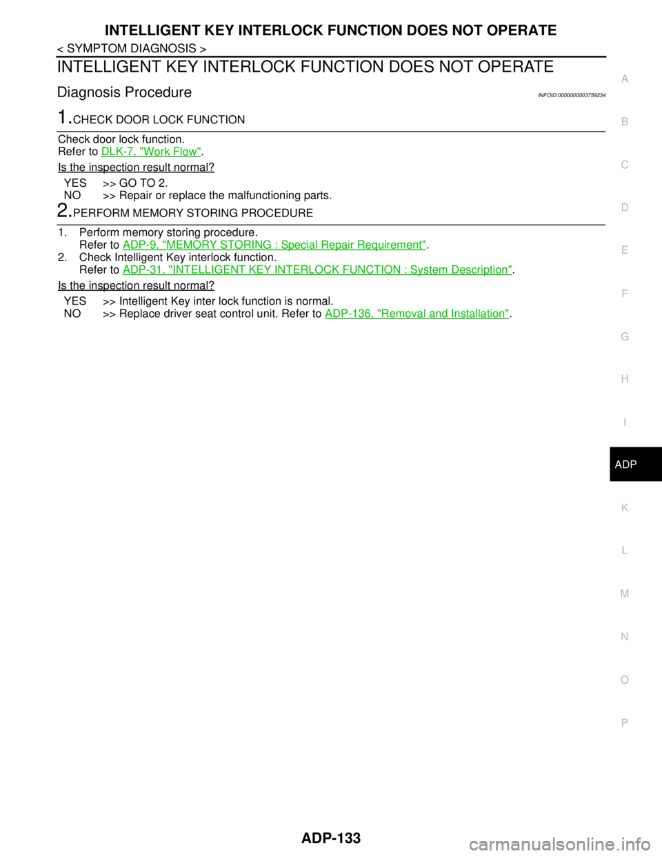
INTELLIGENT KEY INTERLOCK FUNCTION DOES NOT OPERATE
Diagnosis ProcedureINFOID:0000000003759234
1.CHECK DOOR LOCK FUNCTION
Check door lock function.
Refer to DLK-7, "
Work Flow".
Is the inspection result normal?
YES >> GO TO 2.
NO >> Repair or replace the malfunctioning parts.
2.PERFORM MEMORY STORING PROCEDURE
1. Perform memory storing procedure.
Refer to ADP-9, "
MEMORY STORING : Special Repair Requirement".
2. Check Intelligent Key interlock function.
Refer to ADP-31, "
INTELLIGENT KEY INTERLOCK FUNCTION : System Description".
Is the inspection result normal?
YES >> Intelligent Key inter lock function is normal.
NO >> Replace driver seat control unit. Refer to ADP-136, "
Removal and Installation".
Page 823 of 5121
BCS-6
< FUNCTION DIAGNOSIS >
BODY CONTROL SYSTEM
FUNCTION DIAGNOSIS
BODY CONTROL SYSTEM
System DescriptionINFOID:0000000003809584
OUTLINE
BCM (Body Control Module) controls the various electrical components. It inputs the information required to
the control from CAN communication and the signal received from each switch and sensor.
BCM has combination switch reading function for reading the operation status of combination switches (light,
turn signal, wiper and washer) in addition to a function for controlling the operation of various electrical com-
ponents. It also has the signal transmission function as the passed point of signal and the power saving con-
trol function that reduces the power consumption with the ignition switch OFF.
BCM is equipped with the diagnosis function that performs the diagnosis with CONSULT-III and various set-
tings.
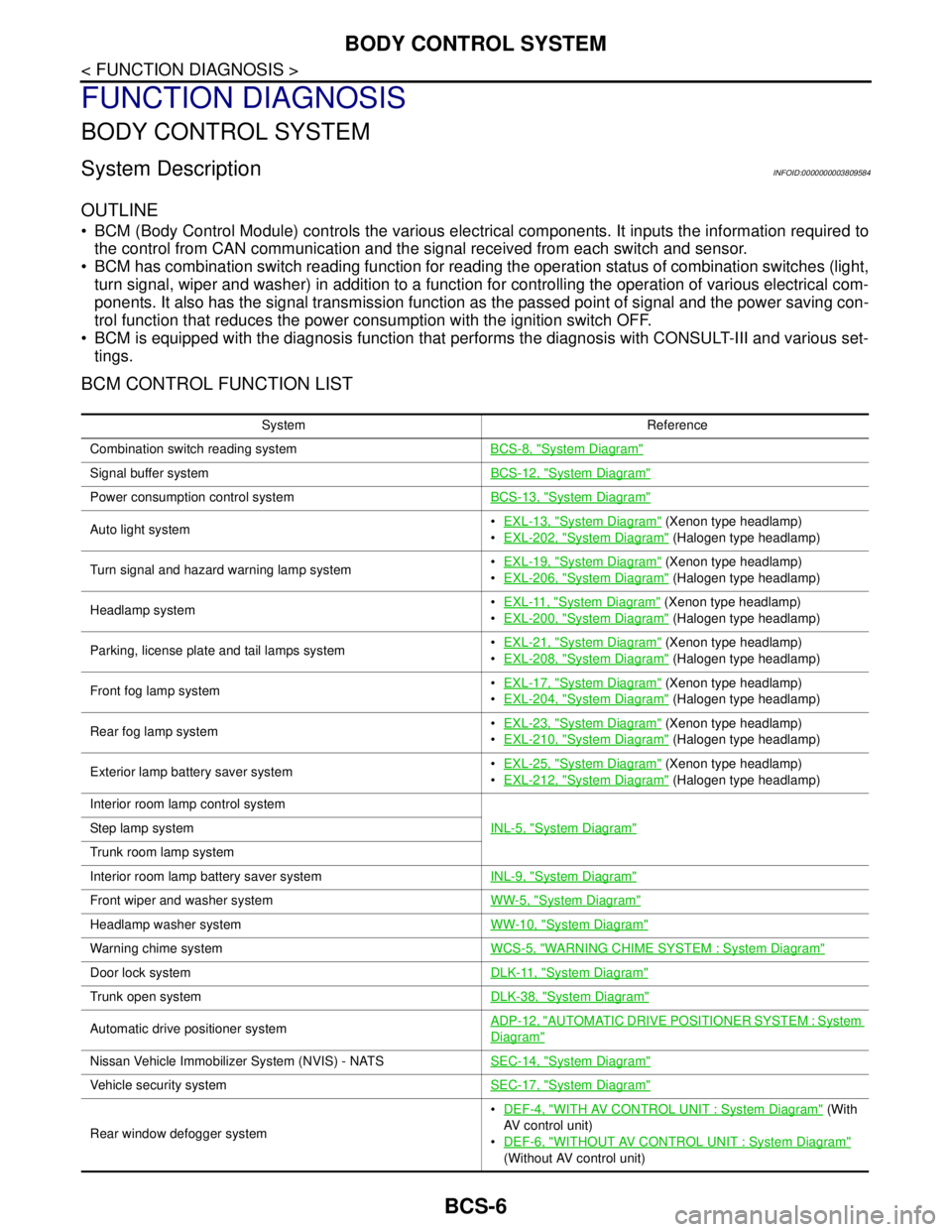
BCM CONTROL FUNCTION LIST
System Reference
Combination switch reading systemBCS-8, "
System Diagram"
Signal buffer systemBCS-12, "System Diagram"
Power consumption control systemBCS-13, "System Diagram"
Auto light systemEXL-13, "System Diagram" (Xenon type headlamp)
EXL-202, "
System Diagram" (Halogen type headlamp)
Turn signal and hazard warning lamp systemEXL-19, "
System Diagram" (Xenon type headlamp)
EXL-206, "
System Diagram" (Halogen type headlamp)
Headlamp systemEXL-11, "
System Diagram" (Xenon type headlamp)
EXL-200, "
System Diagram" (Halogen type headlamp)
Parking, license plate and tail lamps systemEXL-21, "
System Diagram" (Xenon type headlamp)
EXL-208, "
System Diagram" (Halogen type headlamp)
Front fog lamp systemEXL-17, "
System Diagram" (Xenon type headlamp)
EXL-204, "
System Diagram" (Halogen type headlamp)
Rear fog lamp systemEXL-23, "
System Diagram" (Xenon type headlamp)
EXL-210, "
System Diagram" (Halogen type headlamp)
Exterior lamp battery saver systemEXL-25, "
System Diagram" (Xenon type headlamp)
EXL-212, "
System Diagram" (Halogen type headlamp)
Interior room lamp control system
INL-5, "
System Diagram"Step lamp system
Trunk room lamp system
Interior room lamp battery saver systemINL-9, "
System Diagram"
Front wiper and washer systemWW-5, "System Diagram"
Headlamp washer systemWW-10, "System Diagram"
Warning chime systemWCS-5, "WARNING CHIME SYSTEM : System Diagram"
Door lock systemDLK-11, "System Diagram"
Trunk open systemDLK-38, "System Diagram"
Automatic drive positioner systemADP-12, "AUTOMATIC DRIVE POSITIONER SYSTEM : System
Diagram"
Nissan Vehicle Immobilizer System (NVIS) - NATSSEC-14, "System Diagram"
Vehicle security systemSEC-17, "System Diagram"
Rear window defogger systemDEF-4, "
WITH AV CONTROL UNIT : System Diagram" (With
AV control unit)
DEF-6, "
WITHOUT AV CONTROL UNIT : System Diagram"
(Without AV control unit)
Page 824 of 5121

BCS
BODY CONTROL SYSTEM
BCS-7
< FUNCTION DIAGNOSIS >
C
D
E
F
G
H
I
J
K
L B A
O
P N
Component Parts LocationINFOID:0000000003809585
Intelligent Key system/engine start systemDoor lock function
DLK-14, "INTELLIGENT KEY SYSTEM : System Diagram"
Trunk open function
Remote keyless entry
function
Key reminder function
Warning function
Engine start function
Power window systemPWC-7, "
SystemDiagram"
System Reference
1. BCM
A. Behind of combination meter
JPMIA1040ZZ
Page 892 of 5121
BCS
BCM (BODY CONTROL MODULE)
BCS-75
< ECU DIAGNOSIS >
C
D
E
F
G
H
I
J
K
L B A
O
P N
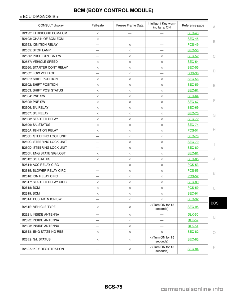
B2192: ID DISCORD BCM-ECM×——SEC-43
B2193: CHAIN OF BCM-ECM×——SEC-45
B2553: IGNITION RELAY —×—PCS-49
B2555: STOP LAMP —×—SEC-50
B2556: PUSH-BTN IGN SW —××SEC-52
B2557: VEHICLE SPEED×××SEC-54
B2560: STARTER CONT RELAY×××SEC-55
B2562: LOW VOLTAGE —×—BCS-36
B2601: SHIFT POSITION×××SEC-56
B2602: SHIFT POSITION×××SEC-59
B2603: SHIFT POSI STATUS×××SEC-61
B2604: PNP SW×××SEC-64
B2605: PNP SW×××SEC-67
B2606: S/L RELAY×××SEC-69
B2607: S/L RELAY×××SEC-70
B2608: STARTER RELAY×××SEC-72
B2609: S/L STATUS×××SEC-74
B260A: IGNITION RELAY×××PCS-51
B260B: STEERING LOCK UNIT —××SEC-78
B260C: STEERING LOCK UNIT —××SEC-79
B260D: STEERING LOCK UNIT —××SEC-80
B260F: ENG STATE SIG LOST×××SEC-81
B2612: S/L STATUS×××SEC-85
B2614: ACC RELAY CIRC —××PCS-53
B2615: BLOWER RELAY CIRC —××PCS-55
B2616: IGN RELAY CIRC —××PCS-57
B2617: STARTER RELAY CIRC×××SEC-89
B2618: BCM×××PCS-59
B2619: BCM×××SEC-91
B261A: PUSH-BTN IGN SW —××SEC-92
B261E: VEHICLE TYPE××× (Turn ON for 15
seconds)SEC-95
B2621: INSIDE ANTENNA —×—DLK-50
B2622: INSIDE ANTENNA —×—DLK-52
B2623: INSIDE ANTENNA —×—DLK-54
B26E1: ENG STATE NO RES×××SEC-82
B26E9: S/L STATUS××× (Turn ON for 15
seconds)SEC-83
B26EA: KEY REGISTRATION —×× (Turn ON for 15
seconds)SEC-84
CONSULT display Fail-safe Freeze Frame DataIntelligent Key warn-
ing lamp ONReference page
Page 1137 of 5121
CO-14
< ON-VEHICLE REPAIR >
RADIATOR
WARNING:
Never remove radiator cap when engine is hot. Serious burns could occur from high-pressure engine
coolant escaping from radiator. Wrap a thick cloth around the cap. Slowly turn it a quarter of a turn to
release built-up pressure. Carefully remove radiator cap by turning it all the way.
1. Remove the following parts:
Engine under cover.
Air duct (inlet): Refer to EM-26, "
Exploded View".
Horn: Refer to HRN-6, "
Exploded View".
Hood lock: Refer to DLK-220, "
Exploded View".
2. Drain engine coolant from radiator. Refer to CO-8, "
Draining".
CAUTION:
Perform this step when the engine is cold.
Never spill engine coolant on drive belt.
3. Disconnect reservoir tank hose from radiator pipe (upper).
4. Disconnect CVT fluid cooler hoses from radiator.
Install blind plug to avoid leakage of CVT fluid.
5. Disconnect Low-pressure flexible hose from lower pressure pipe, and then move it to aside. Refer to HA-
38, "Exploded View".
6. Remove radiator cap adapter and radiator hoses (upper) and radiator pipe (upper) assembly.
CAUTION:
Be careful not to allow engine coolant to contact drive belt.
7. Disconnect radiator hose (lower) from radiator.
8. Remove condenser. Refer to HA-46, "
Exploded View".
CAUTION:
Be careful not to damage condenser core.
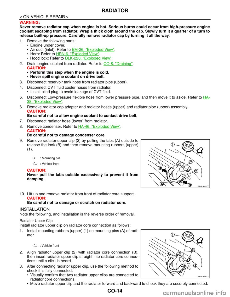
9. Remove radiator upper clip (2) by pulling the tabs (A) outside to
release the lock (B) and then remove mounting rubbers (upper)
(1).
CAUTION:
Never pull the tabs outside excessively to prevent it from
damping.
10. Lift up and remove radiator from front of radiator core support.
CAUTION:
Be careful not to damage or scratch on radiator core.
INSTALLATION
Note the following, and installation is the reverse order of removal.
Radiator Upper Clip
Install radiator upper clip on radiator core connection as follows:
1. Install mounting rubbers (upper) (1) on mounting pins (A) of radi-
ator.
2. Align radiator upper clip (2) with radiator core connection (B),
then insert radiator upper clip straight into radiator core connec-
tions until a click is heard.
3. After connecting radiator upper clip, use the following method to
check it is fully connected.
Visually confirm that two radiator upper clips are connected to
radiator core connections.
Move radiator upper clip and the radiator forward and backward to check they are securely connected.
C : Mounting pin
: Vehicle front
JPBIA1689ZZ
: Vehicle front
JPBIA1690ZZ
Page 1207 of 5121
BCM (BODY CONTROL MODULE)
DEF-57
< ECU DIAGNOSIS >
C
D
E
F
G
H
I
J
K
MA
B
DEF
N
O
P
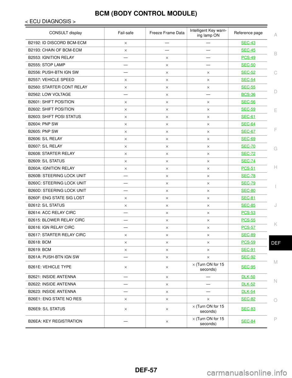
B2192: ID DISCORD BCM-ECM×——SEC-43
B2193: CHAIN OF BCM-ECM×——SEC-45
B2553: IGNITION RELAY —×—PCS-49
B2555: STOP LAMP —×—SEC-50
B2556: PUSH-BTN IGN SW —××SEC-52
B2557: VEHICLE SPEED×××SEC-54
B2560: STARTER CONT RELAY×××SEC-55
B2562: LOW VOLTAGE —×—BCS-36
B2601: SHIFT POSITION×××SEC-56
B2602: SHIFT POSITION×××SEC-59
B2603: SHIFT POSI STATUS×××SEC-61
B2604: PNP SW×××SEC-64
B2605: PNP SW×××SEC-67
B2606: S/L RELAY×××SEC-69
B2607: S/L RELAY×××SEC-70
B2608: STARTER RELAY×××SEC-72
B2609: S/L STATUS×××SEC-74
B260A: IGNITION RELAY×××PCS-51
B260B: STEERING LOCK UNIT —××SEC-78
B260C: STEERING LOCK UNIT —××SEC-79
B260D: STEERING LOCK UNIT —××SEC-80
B260F: ENG STATE SIG LOST×××SEC-81
B2612: S/L STATUS×××SEC-85
B2614: ACC RELAY CIRC —××PCS-53
B2615: BLOWER RELAY CIRC —××PCS-55
B2616: IGN RELAY CIRC —××PCS-57
B2617: STARTER RELAY CIRC×××SEC-89
B2618: BCM×××PCS-59
B2619: BCM×××SEC-91
B261A: PUSH-BTN IGN SW —××SEC-92
B261E: VEHICLE TYPE××× (Turn ON for 15
seconds)SEC-95
B2621: INSIDE ANTENNA —×—DLK-50
B2622: INSIDE ANTENNA —×—DLK-52
B2623: INSIDE ANTENNA —×—DLK-54
B26E1: ENG STATE NO RES×××SEC-82
B26E9: S/L STATUS××× (Turn ON for 15
seconds)SEC-83
B26EA: KEY REGISTRATION —×× (Turn ON for 15
seconds)SEC-84
CONSULT display Fail-safe Freeze Frame DataIntelligent Key warn-
ing lamp ONReference page
Page 1217 of 5121
DLK-1
BODY EXTERIOR, DOORS, ROOF & VEHICLE SECURITY
C
D
E
F
G H
I
J
L
M
SECTION DLK
A
B
DLK
N
O P
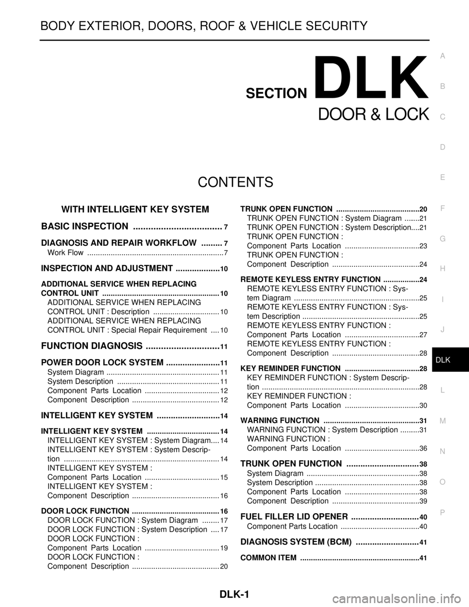
CONTENTS
DOOR & LOCK
WITH INTELLIGE NT KEY SYSTEM
BASIC INSPECTION ....... .............................
7
DIAGNOSIS AND REPAIR WORKFLOW ..... .....7
Work Flow ........................................................... ......7
INSPECTION AND ADJUSTMENT ....................10
ADDITIONAL SERVICE WHEN REPLACING
CONTROL UNIT .................................................... ....
10
ADDITIONAL SERVICE WHEN REPLACING
CONTROL UNIT : Description ................................
10
ADDITIONAL SERVICE WHEN REPLACING
CONTROL UNIT : Special Repair Requirement .....
10
FUNCTION DIAGNOSIS .. ............................11
POWER DOOR LOCK SYSTEM .................... ....11
System Diagram .................................................. ....11
System Description .................................................11
Component Parts Location ....................................12
Component Description ..........................................12
INTELLIGENT KEY SYSTEM ............................14
INTELLIGENT KEY SYSTEM ...................................14
INTELLIGENT KEY SYSTEM : System Diagram ....14
INTELLIGENT KEY SYSTEM : System Descrip-
tion ..........................................................................
14
INTELLIGENT KEY SYSTEM :
Component Parts Location ....................................
15
INTELLIGENT KEY SYSTEM :
Component Description ..........................................
16
DOOR LOCK FUNCTION ...................................... ....16
DOOR LOCK FUNCTION : System Diagram .........17
DOOR LOCK FUNCTION : System Description .....17
DOOR LOCK FUNCTION :
Component Parts Location ....................................
19
DOOR LOCK FUNCTION :
Component Description ..........................................
20
TRUNK OPEN FUNCTION .................................... ....20
TRUNK OPEN FUNCTION : System Diagram ........21
TRUNK OPEN FUNCTION : System Description ....21
TRUNK OPEN FUNCTION :
Component Parts Location ....................................
23
TRUNK OPEN FUNCTION :
Component Description ..........................................
24
REMOTE KEYLESS ENTRY FUNCTION ..................24
REMOTE KEYLESS ENTRY FUNCTION : Sys-
tem Diagram ........................................................ ....
25
REMOTE KEYLESS ENTRY FUNCTION : Sys-
tem Description ........................................................
25
REMOTE KEYLESS ENTRY FUNCTION :
Component Parts Location ....................................
27
REMOTE KEYLESS ENTRY FUNCTION :
Component Description ..........................................
28
KEY REMINDER FUNCTION ................................ ....28
KEY REMINDER FUNCTION : System Descrip-
tion ...........................................................................
28
KEY REMINDER FUNCTION :
Component Parts Location ....................................
30
WARNING FUNCTION .......................................... ....31
WARNING FUNCTION : System Description ..........31
WARNING FUNCTION :
Component Parts Location ................................ ....
36
TRUNK OPEN FUNCTION ...............................38
System Diagram ......................................................38
System Description ..................................................38
Component Parts Location ....................................38
Component Description ..........................................39
FUEL FILLER LID OPENER .............................40
Component Parts Location ......................................40
DIAGNOSIS SYSTEM (BCM) ...........................41
COMMON ITEM ..................................................... ....41