heater NISSAN TEANA 2008 Service Manual
[x] Cancel search | Manufacturer: NISSAN, Model Year: 2008, Model line: TEANA, Model: NISSAN TEANA 2008Pages: 5121, PDF Size: 69.03 MB
Page 1 of 5121
MODEL J32 SERIES
© 2008 NISSAN INTERNATIONAL SA
Allrightsreserved.NopartofthisElectronicServiceManualmaybereproducedorstoredinaretrievalsystem,ortransmittedinanyform,or by any means, electronic, mechanical, photocopying, recording or otherwise, without the prior written permission of Nissan InternationalSA, Switzerland.
AGENERALINFORMATION
BENGINE
DTRANSMISSION&DRIVELINE
ESUSPENSION
FBRAKES
GSTEERING
HRESTRAINTS
IVENTILATION,HEATER&AIRCONDITIONER
JBODYINTERIOR
KBODYEXTERIOR,DOOR,ROOF&VEHICLESECURITY
LDRIVERCONTROLS
MELECTRICAL&POWERCONTROL
NDRIVERINFORMATION&MULTIMEDIA
PMAINTENANCE
GIGeneralInformation
EMEngineMechanical
LUEngineLubricationSystem
COEngineCoolingSystem
ECEngineControlSystem
FLFuelSystem
EXExhaustSystem
STRStartingSystem
ACCAcceleratorControlSystem
TMTransaxle &Transmission
FAXFrontAxle
RAXRearAxle
FSUFrontSuspension
RSURearSuspension
WTRoadWheels &Tires
BRBrakeSystem
PBParkingBrakeSystem
BRCBrakeControlSystem
STSteeringSystem
STCSteeringControlSystem
SBSeatBelt
SRSRSAirbag
SRCSRSAirbagControlSystem
VTLVentilationSystem
HAHeater &AirConditioningSystem
HACHeater &AirConditioningControlSystem
INTInterior
IPInstrumentPanel
SESeat
ADPAutomaticDrivePositioner
DLKDoor &Lock
SECSecurityControlSystem
GWGlass &WindowSystem
PWCPowerWindowControlSystem
RFRoof
EXTExterior
MIRMirrors
EXLExteriorLightingSystem
INLInteriorLightingSystem
WWWiper &Washer
DEFDefogger
HRNHorn
PWOPowerOutlet
BCSBodyControlSystem
LANLANSystem
PCSPowerControlSystem
CHGChargingSystem
PGPowerSupply,Ground&CircuitElements
MWIMeter,WarningLamp&Indicator
WCSWarningChimeSystem
AVAudio,Visual&NavigationSystem
MAMaintenance
QUICKREFERENCEINDEX
A
B
C
D
E
F
G
H
I
J
K
L
M
N
O
P
M
Publication Number:
SM8E00-1J32E0E
Page 179 of 5121
![NISSAN TEANA 2008 Service Manual AV
NORMAL OPERATING CONDITION
AV-35
< SYMPTOM DIAGNOSIS >[AUDIO SYSTEM]
C
D
E
F
G
H
I
J
K
L
MB A
O
P
NORMAL OPERATING CONDITION
DescriptionINFOID:0000000003765606
NOTE:
Audio operation information, NISSAN TEANA 2008 Service Manual AV
NORMAL OPERATING CONDITION
AV-35
< SYMPTOM DIAGNOSIS >[AUDIO SYSTEM]
C
D
E
F
G
H
I
J
K
L
MB A
O
P
NORMAL OPERATING CONDITION
DescriptionINFOID:0000000003765606
NOTE:
Audio operation information,](/img/5/57391/w960_57391-178.png)
AV
NORMAL OPERATING CONDITION
AV-35
< SYMPTOM DIAGNOSIS >[AUDIO SYSTEM]
C
D
E
F
G
H
I
J
K
L
MB A
O
P
NORMAL OPERATING CONDITION
DescriptionINFOID:0000000003765606
NOTE:
Audio operation information, refer to Owner's Manual.
The majority of the audio concerns are the result of outside causes (bad CD, electromagnetic interference,
etc.).
NOISE
The following noise results from variations in field strength, such as fading noise and multi-path noise, or
external noise from trains and other sources. It is not a malfunction.
Fading noise: This noise occurs because of variations in the field strength in a narrow range due to moun-
tains or buildings blocking the signal.
Multi-path noise: This noise results from the waves sent directly from the broadcast station arriving at the
antenna at a different time from the waves that reflect off mountains or buildings.
The vehicle itself can be a source of noise if noise prevention parts or electrical equipment is malfunctioning.
Check if noise is caused and/or changed by engine speed, ignition switch turned to each position, and opera-
tion of each piece of electrical equipment, and then determine the cause.
NOTE:
The source of the noise can be easily found by listening to the noise while removing the fuses of electrical
components, one by one.
Types of Noise and Possible Causes
Occurrence condition Possible cause
Occurs only when engine is ON.A continuous growling noise occurs. The speed of
the noise varies with changes in the engine speed. Ignition components
The occurrence of the noise is linked with the operation of the fuel pump. Fuel pump condenser
Noise only occurs when various
electrical components are oper-
ating.A cracking or snapping sound occurs with the op-
eration of various switches. Relay malfunction, audio unit malfunction
The noise occurs when various motors are operat-
ing. Motor case ground
Motor
The noise occurs constantly, not just under certain conditions. Rear defogger coil malfunction
Open circuit in printed heater
Poor ground of antenna feeder line
A cracking or snapping sound occurs while the vehicle is being driven, especially when
it is vibrating excessively. Ground wire of body parts
Ground due to improper part installation
Wiring connections or a short circuit
Page 1132 of 5121
ENGINE COOLANT
CO-9
< ON-VEHICLE MAINTENANCE >
C
D
E
F
G
H
I
J
K
L
MA
CO
N
P O
4. Check drained engine coolant for contaminants such as rust, corrosion or discoloration.
If contaminated, flush the engine cooling system. Refer to CO-10, "
Flushing".
RefillingINFOID:0000000003793168
1. Install reservoir tank if removed, and radiator drain plug.
CAUTION:
Be sure to clean drain plug and install with new O-ring.
If water drain plugs on cylinder block are removed, close and tighten them. Refer to EM-110, "
Dis-
assembly and Assembly".
2. Check that each hose clamp has been firmly tightened.
3. Remove air duct assembly and air cleaner cases (upper and lower) assembly. Refer to EM-26, "
Exploded
View".
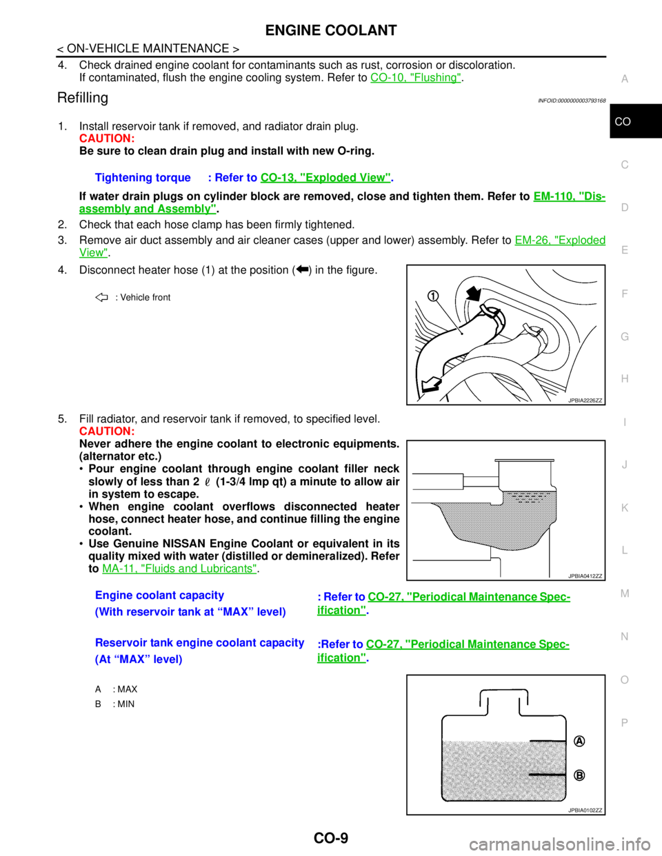
4. Disconnect heater hose (1) at the position ( ) in the figure.
5. Fill radiator, and reservoir tank if removed, to specified level.
CAUTION:
Never adhere the engine coolant to electronic equipments.
(alternator etc.)
Pour engine coolant through engine coolant filler neck
slowly of less than 2 (1-3/4 lmp qt) a minute to allow air
in system to escape.
When engine coolant overflows disconnected heater
hose, connect heater hose, and continue filling the engine
coolant.
Use Genuine NISSAN Engine Coolant or equivalent in its
quality mixed with water (distilled or demineralized). Refer
to MA-11, "
Fluids and Lubricants". Tightening torque : Refer to CO-13, "
Exploded View".
: Vehicle front
JPBIA2226ZZ
Engine coolant capacity
: Refer to CO-27, "Periodical Maintenance Spec-
ification".
(With reservoir tank at “MAX” level)
Reservoir tank engine coolant capacity
:Refer to CO-27, "
Periodical Maintenance Spec-
ification".
(At “MAX” level)
A : MAX
B: MIN
JPBIA0412ZZ
JPBIA0102ZZ
Page 1133 of 5121
CO-10
< ON-VEHICLE MAINTENANCE >
ENGINE COOLANT
6. Install air duct assembly and air cleaner cases (upper and lower) assembly. Refer to EM-26, "Exploded
View".
7. Install radiator cap.
8. Warm up engine until opening thermostat. Standard for warming-up time is approximately 10 minutes at
3,000 rpm.
Check thermostat opening condition by touching radiator hose (lower) to see a flow of warm water.
CAUTION:
Watch water temperature gauge so as not to overheat engine.
9. Stop the engine and cool down to less than approximately 50°C (122°F).
Cool down using fan to reduce the time.
If necessary, refill radiator up to filler neck with engine coolant.
CAUTION:
Never adhere the engine coolant to electronic equipments. (alternator etc.)
10. Refill reservoir tank to “MAX” level line with engine coolant.
11. Repeat steps 7 through 10 two or more times with radiator cap installed until engine coolant level no
longer drops.
12. Check cooling system for leakage with engine running.
13. Warm up the engine, and check for sound of engine coolant flow while running engine from idle up to
3,000 rpm with heater temperature controller set at several position between “COOL” and “WARM”.
Sound may be noticeable at heater unit.
14. Repeat step 13 three times.
15. If sound is heard, bleed air from cooling system by repeating step 5, and steps from 7 to 14 until engine
coolant level no longer drops.
FlushingINFOID:0000000003793169
1. Install reservoir tank if removed, and radiator drain plug.
CAUTION:
Be sure to clean drain plug and install with new O-ring.
If water drain plugs on cylinder block are removed, close and tighten them. Refer to EM-110, "
Dis-
assembly and Assembly".
2. Remove air duct assembly and air cleaner cases (upper and lower) assembly. Refer to EM-26, "
Exploded
View".
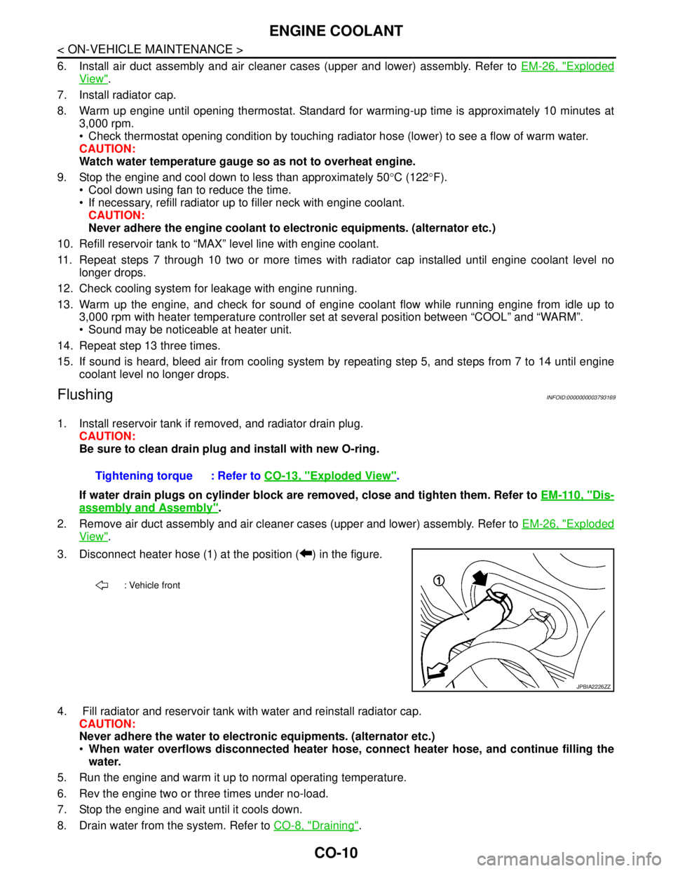
3. Disconnect heater hose (1) at the position ( ) in the figure.
4. Fill radiator and reservoir tank with water and reinstall radiator cap.
CAUTION:
Never adhere the water to electronic equipments. (alternator etc.)
When water overflows disconnected heater hose, connect heater hose, and continue filling the
water.
5. Run the engine and warm it up to normal operating temperature.
6. Rev the engine two or three times under no-load.
7. Stop the engine and wait until it cools down.
8. Drain water from the system. Refer to CO-8, "
Draining". Tightening torque : Refer to CO-13, "
Exploded View".
: Vehicle front
JPBIA2226ZZ
Page 1148 of 5121
WATER OUTLET AND WATER PIPING
CO-25
< ON-VEHICLE REPAIR >
C
D
E
F
G
H
I
J
K
L
MA
CO
N
P O
WATER OUTLET AND WATER PIPING
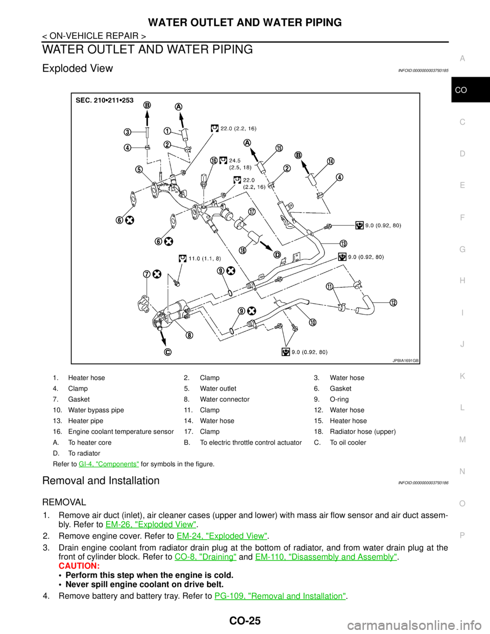
Exploded ViewINFOID:0000000003793185
Removal and InstallationINFOID:0000000003793186
REMOVAL
1. Remove air duct (inlet), air cleaner cases (upper and lower) with mass air flow sensor and air duct assem-
bly. Refer to EM-26, "
Exploded View".
2. Remove engine cover. Refer to EM-24, "
Exploded View".
3. Drain engine coolant from radiator drain plug at the bottom of radiator, and from water drain plug at the
front of cylinder block. Refer to CO-8, "
Draining" and EM-110, "Disassembly and Assembly".
CAUTION:
Perform this step when the engine is cold.
Never spill engine coolant on drive belt.
4. Remove battery and battery tray. Refer to PG-109, "
Removal and Installation".
1. Heater hose 2. Clamp 3. Water hose
4. Clamp 5. Water outlet 6. Gasket
7. Gasket 8. Water connector 9. O-ring
10. Water bypass pipe 11. Clamp 12. Water hose
13. Heater pipe 14. Water hose 15. Heater hose
16. Engine coolant temperature sensor 17. Clamp 18. Radiator hose (upper)
A. To heater core B. To electric throttle control actuator C. To oil cooler
D. To radiator
Refer to GI-4, "
Components" for symbols in the figure.
JPBIA1691GB
Page 1149 of 5121
CO-26
< ON-VEHICLE REPAIR >
WATER OUTLET AND WATER PIPING
5. Remove CVT fluid charging pipe and CVT fluid level gauge. Refer to TM-332, "Exploded View" (VQ25DE)
or TM-168, "
Exploded View" (VQ35DE).
6. Move CVT control cable aside. Refer to TM-319, "
Exploded View" (VQ25DE) or TM-157, "Exploded View"
(VQ35DE).
7. Remove vacuum pipe (front) mounting bolt from water outlet. Refer to EM-67, "
Exploded View".
8. Remove radiator hose (upper) from water outlet.
9. Remove water hoses and heater hoses.
10. Disconnect harness connectors, and move harness to aside.
11. Remove engine coolant temperature sensor as necessary.
CAUTION:
Be careful not to damage engine coolant temperature sensor.
12. Remove water outlet, heater pipe, water bypass pipe and water connector.
INSTALLATION
Note the following, and install in the reverse order of removal.
Securely insert each hose, and install clamp at a position where it does not interfere with the pipe bulge.
When inserting water bypass pipe and heater pipe into water connector, apply neutral detergent to O-ring.
InspectionINFOID:0000000003793187
INSPECTION AFTER INSTALLATION
Check for leakage of engine coolant using the radiator cap tester adapter (commercial service tool) and the
radiator cap tester (commercial service tool). Refer to CO-8, "
Inspection".
Start and warm up the engine. Visually check that there is no leakage of engine coolant.
Page 1463 of 5121

EC-2
Component Parts Location ...................................53
Component Description .........................................58
CAN COMMUNICATION ...................................59
System Description .................................................59
COOLING FAN CONTROL ...............................60
System Diagram .....................................................60
System Description .................................................60
Component Parts Location ...................................62
Component Description ..........................................67
ELECTRONIC CONTROLLED ENGINE
MOUNT ..............................................................
68
System Diagram .....................................................68
System Description .................................................69
Component Parts Location ...................................70
Component Description .........................................75
EVAPORATIVE EMISSION SYSTEM ...............76
System Diagram .....................................................76
System Description .................................................76
Component Parts Location ...................................80
Component Description .........................................85
INTAKE VALVE TIMING CONTROL .................86
System Diagram .....................................................86
System Description .................................................86
Component Parts Location ...................................87
Component Description ..........................................92
VARIABLE INDUCTION AIR SYSTEM .............93
System Diagram .....................................................93
System Description .................................................93
Component Parts Location ...................................96
Component Description ........................................101
ON BOARD DIAGNOSTIC (OBD) SYSTEM ...102
Diagnosis Description ............................................102
CONSULT-III Function ..........................................113
Diagnosis Tool Function ......................................122
COMPONENT DIAGNOSIS .......................124
TROUBLE DIAGNOSIS - SPECIFICATION
VALUE .............................................................
124
Description .............................................................124
Component Function Check ..................................124
Diagnosis Procedure .............................................125
POWER SUPPLY AND GROUND CIRCUIT ...132
Diagnosis Procedure .............................................132
U1000, U1001 CAN COMM CIRCUIT .............135
Description .............................................................135
DTC Logic ..............................................................135
Diagnosis Procedure .............................................135
P0011, P0021 IVT CONTROL .........................136
DTC Logic ..............................................................136
Diagnosis Procedure .............................................137
Component Inspection ..........................................138
P0031, P0032, P0051, P0052 A/F SENSOR 1
HEATER ...........................................................
140
Description ............................................................140
DTC Logic .............................................................140
Diagnosis Procedure .............................................140
Component Inspection ..........................................142
P0037, P0038, P0057, P0058 HO2S2 HEAT-
ER .....................................................................
143
Description ............................................................143
DTC Logic .............................................................143
Diagnosis Procedure .............................................144
Component Inspection ..........................................145
P0075, P0081 IVT CONTROL SOLENOID
VALVE ..............................................................
146
Description ............................................................146
DTC Logic .............................................................146
Diagnosis Procedure .............................................146
Component Inspection ..........................................147
P0102, P0103 MAF SENSOR ..........................149
Description ............................................................149
DTC Logic .............................................................149
Diagnosis Procedure .............................................150
Component Inspection ..........................................151
P0112, P0113 IAT SENSOR ............................154
Description ............................................................154
DTC Logic .............................................................154
Diagnosis Procedure .............................................155
Component Inspection ..........................................155
P0117, P0118 ECT SENSOR ...........................157
Description ............................................................157
DTC Logic .............................................................157
Diagnosis Procedure .............................................158
Component Inspection ..........................................158
P0122, P0123 TP SENSOR ..............................160
Description ............................................................160
DTC Logic .............................................................160
Diagnosis Procedure .............................................160
Component Inspection ..........................................162
Special Repair Requirement .................................162
P0130, P0150 A/F SENSOR 1 .........................163
Description ............................................................163
DTC Logic .............................................................163
Component Function Check .................................165
Diagnosis Procedure .............................................165
P0131, P0151 A/F SENSOR 1 .........................167
Description ............................................................167
DTC Logic .............................................................167
Diagnosis Procedure .............................................168
P0132, P0152 A/F SENSOR 1 .........................170
Description ............................................................170
Page 1486 of 5121
![NISSAN TEANA 2008 Service Manual ENGINE CONTROL SYSTEM
EC-25
< FUNCTION DIAGNOSIS >[VQ25DE, VQ35DE]
C
D
E
F
G
H
I
J
K
L
MA
EC
N
P O
Component DescriptionINFOID:0000000003856464
1. Fuel level sensor unit and fuel pump
harness connect NISSAN TEANA 2008 Service Manual ENGINE CONTROL SYSTEM
EC-25
< FUNCTION DIAGNOSIS >[VQ25DE, VQ35DE]
C
D
E
F
G
H
I
J
K
L
MA
EC
N
P O
Component DescriptionINFOID:0000000003856464
1. Fuel level sensor unit and fuel pump
harness connect](/img/5/57391/w960_57391-1485.png)
ENGINE CONTROL SYSTEM
EC-25
< FUNCTION DIAGNOSIS >[VQ25DE, VQ35DE]
C
D
E
F
G
H
I
J
K
L
MA
EC
N
P O
Component DescriptionINFOID:0000000003856464
1. Fuel level sensor unit and fuel pump
harness connector2. Fuel pressure regulator 3. Fuel level sensor unit and fuel pump
: Vehicle front
JMBIA1385ZZ
Component Reference
A/F sensor 1EC-163, "
Description"
A/F sensor 1 heaterEC-140, "Description"
Accelerator pedal position sensorEC-304, "Description"
ASCD brake switchEC-273, "Description"
ASCD steering switchEC-270, "Description"
Battery current sensorEC-258, "Description"
Camshaft position sensor (PHASE)EC-222, "Description"
Crankshaft position sensor (POS)EC-218, "Description"
Cooling fan motorEC-324, "Description"
Electric throttle control actuatorEC-302, "Description"
Electronic controlled engine mountEC-331, "Description"
Engine coolant temperature sensorEC-157, "Description"
EVAP canister purge volume control solenoid valveEC-231, "Description"
Fuel injectorEC-334, "Description"
Fuel pumpEC-337, "Description"
Heated oxygen sensor 2EC-178, "Description"
Heated oxygen sensor 2 heaterEC-143, "Description"
Ignition coil with power transistorEC-341, "Description"
Intake air temperature sensorEC-154, "Description"
Intake valve timing control solenoid valveEC-146, "Description"
Knock sensorEC-215, "Description"
Mass air flow sensorEC-149, "Description"
PCV valveEC-347, "Description"
Power steering pressure sensorEC-236, "Description"
Power valves 1 and 2EC-351, "Description"
Refrigerant pressure sensorEC-348, "Description"
Stop lamp switchEC-291, "Description"
TCM (VQ35DE engine)
Park/neutral position (PNP) switch (VQ25DE engine)EC-245, "Description"
Throttle control motorEC-300, "Description"
Page 1576 of 5121
![NISSAN TEANA 2008 Service Manual ON BOARD DIAGNOSTIC (OBD) SYSTEM
EC-115
< FUNCTION DIAGNOSIS >[VQ25DE, VQ35DE]
C
D
E
F
G
H
I
J
K
L
MA
EC
N
P O
X: Applicable
*1: This item includes 1st trip DTCs.
*2: This mode includes 1st trip freez NISSAN TEANA 2008 Service Manual ON BOARD DIAGNOSTIC (OBD) SYSTEM
EC-115
< FUNCTION DIAGNOSIS >[VQ25DE, VQ35DE]
C
D
E
F
G
H
I
J
K
L
MA
EC
N
P O
X: Applicable
*1: This item includes 1st trip DTCs.
*2: This mode includes 1st trip freez](/img/5/57391/w960_57391-1575.png)
ON BOARD DIAGNOSTIC (OBD) SYSTEM
EC-115
< FUNCTION DIAGNOSIS >[VQ25DE, VQ35DE]
C
D
E
F
G
H
I
J
K
L
MA
EC
N
P O
X: Applicable
*1: This item includes 1st trip DTCs.
*2: This mode includes 1st trip freeze frame data or freeze frame data. The items appear on CONSULT-III screen in freeze frame data
mode only if a 1st trip DTC or DTC is detected. For details, refer to EC-102, "
Diagnosis Description".
*3: Always “CMPLT” is displayed.
WORK SUPPORT MODE
Work Item
*: This function is not necessary in the usual service procedure.
SELF-DIAG RESULTS MODE
Self Diagnostic Item
Regarding items of DTC and 1st trip DTC, refer to EC-389, "DTCIndex".
ENGINE CONTROL COMPONENT PARTS
OUTPUT
Fuel injector××
Power transistor (Ignition timing)××
Throttle control motor relay××
Throttle control motor×
EVAP canister purge volume control
solenoid valve××××
Air conditioner relay×
Fuel pump relay×××
Cooling fan relay×××
Air fuel ratio (A/F) sensor 1 heater××
×*
3
Heated oxygen sensor 2 heater××
×*3
Intake valve timing control solenoid
valve×××
VIAS control solenoid valve 1×××
VIAS control solenoid valve 2×××
Electronic controlled engine mount××
Alternator××
Calculated load value×× ItemDIAGNOSTIC TEST MODE
WORK
SUPPORTSELF-DIAGNOSTIC
RESULTS
DATA
MONI-
TORACTIVE
TESTDTC & SRT
CONFIRMATION
DTC*
1FREEZE
FRAME
DATA*
2
SRT STA-
TUSDTC
WORK
SUP-
PORT
WORK ITEM CONDITION USAGE
FUEL PRESSURE RELEASE FUEL PUMP WILL STOP BY TOUCHING “START” DUR-
ING IDLING.
CRANK A FEW TIMES AFTER ENGINE STALLS.When releasing fuel pressure from
fuel line
IDLE AIR VOL LEARN THE IDLE AIR VOLUME THAT KEEPS THE ENGINE
WITHIN THE SPECIFIED RANGE IS MEMORIZED IN
ECM.When learning the idle air volume
SELF-LEARNING CONT THE COEFFICIENT OF SELF-LEARNING CONTROL
MIXTURE RATIO RETURNS TO THE ORIGINAL COEF-
FICIENT.When clearing mixture ratio self-
learning value
TARGET IDLE RPM ADJ* IDLE CONDITIONWhen setting target idle speed
TARGET IGN TIM ADJ* IDLE CONDITION When adjusting target ignition tim-
ing
Page 1578 of 5121
![NISSAN TEANA 2008 Service Manual ON BOARD DIAGNOSTIC (OBD) SYSTEM
EC-117
< FUNCTION DIAGNOSIS >[VQ25DE, VQ35DE]
C
D
E
F
G
H
I
J
K
L
MA
EC
N
P O
COOLAN TEMP/S°C or °F The engine coolant temperature (determined by
the signal voltag NISSAN TEANA 2008 Service Manual ON BOARD DIAGNOSTIC (OBD) SYSTEM
EC-117
< FUNCTION DIAGNOSIS >[VQ25DE, VQ35DE]
C
D
E
F
G
H
I
J
K
L
MA
EC
N
P O
COOLAN TEMP/S°C or °F The engine coolant temperature (determined by
the signal voltag](/img/5/57391/w960_57391-1577.png)
ON BOARD DIAGNOSTIC (OBD) SYSTEM
EC-117
< FUNCTION DIAGNOSIS >[VQ25DE, VQ35DE]
C
D
E
F
G
H
I
J
K
L
MA
EC
N
P O
COOLAN TEMP/S°C or °F The engine coolant temperature (determined by
the signal voltage of the engine coolant tempera-
ture sensor) is displayed. When the engine coolant temperature
sensor is open or short-circuited,
ECM enters fail-safe mode. The en-
gine coolant temperature determined
by the ECM is displayed.
A/F SEN1 (B1)
V The A/F signal computed from the input signal of
the air fuel ratio (A/F) sensor 1 is displayed.
A/F SEN1 (B2)
HO2S2 (B1)
V The signal voltage of the heated oxygen sensor 2
is displayed.
HO2S2 (B2)
HO2S2 MNTR(B1)
RICH/LEAN Display of heated oxygen sensor 2 signal:
RICH: means the amount of oxygen after three
way catalyst is relatively small.
LEAN: means the amount of oxygen after three
way catalyst is relatively large. When the engine is stopped, a certain
value is indicated.
HO2S2 MNTR(B2)
VHCL SPEED SE km/h or mph The vehicle speed computed from the vehicle
speed signal sent from combination meter is dis-
played.
BATTERY VOLT V The power supply voltage of ECM is displayed.
ACCEL SEN 1
V The accelerator pedal position sensor signal volt-
age is displayed. ACCEL SEN 2 signal is converted by
ECM internally. Thus, it differs from
ECM terminal voltage signal. ACCEL SEN 2
TP SEN 1-B1
V The throttle position sensor signal voltage is dis-
played. TP SEN 2-B1 signal is converted by
ECM internally. Thus, it differs from
ECM terminal voltage signal. TP SEN 2-B1
INT/A TEMP SE°C or °F The intake air temperature (determined by the
signal voltage of the intake air temperature sen-
sor) is indicated.
START SIGNAL ON/OFF Indicates start signal status [ON/OFF] computed
by the ECM according to the signals of engine
speed and battery voltage. After starting the engine, [OFF] is dis-
played regardless of the starter sig-
nal.
CLSD THL POS ON/OFF Indicates idle position [ON/OFF] computed by
ECM according to the accelerator pedal position
sensor signal.
AIR COND SIG ON/OFF Indicates [ON/OFF] condition of the air condition-
er switch as determined by the air conditioner sig-
nal.
P/N POSI SW ON/OFF Indicates [ON/OFF] condition from the park/neu-
tral position (PNP) signal.
PW/ST SIGNAL ON/OFF [ON/OFF] condition of the power steering system
(determined by the signal voltage of the power
steering pressure sensor) is indicated.
LOAD SIGNAL ON/OFF Indicates [ON/OFF] condition from the electrical
load signal.
ON: Rear window defogger switch is ON and/or
lighting switch is in 2nd position.
OFF: Both rear window defogger switch and light-
ing switch are OFF.
IGNITION SW ON/OFF Indicates [ON/OFF] condition from ignition switch
signal.
HEATER FAN SW ON/OFF Indicates [ON/OFF] condition from the heater fan
switch signal.
BRAKE SW ON/OFF Indicates [ON/OFF] condition from the stop lamp
switch signal.
INJ PULSE-B1
msec Indicates the actual fuel injection pulse width
compensated by ECM according to the input sig-
nals. When the engine is stopped, a certain
computed value is indicated.
INJ PULSE-B2Monitored item Unit Description Remarks