high NISSAN TEANA 2008 Service Manual
[x] Cancel search | Manufacturer: NISSAN, Model Year: 2008, Model line: TEANA, Model: NISSAN TEANA 2008Pages: 5121, PDF Size: 69.03 MB
Page 44 of 5121
ADP-38
< COMPONENT DIAGNOSIS >
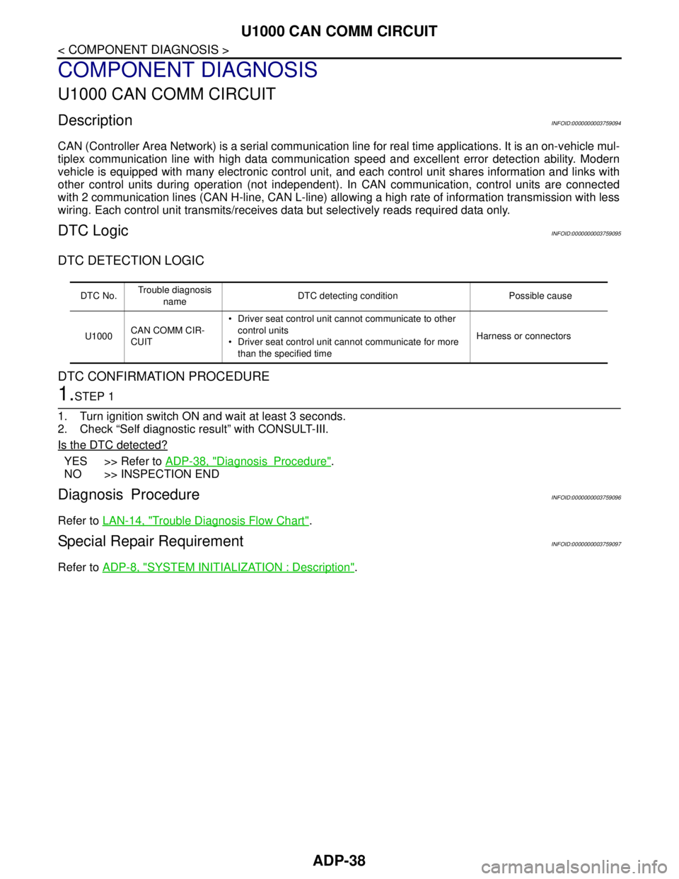
U1000 CAN COMM CIRCUIT
COMPONENT DIAGNOSIS
U1000 CAN COMM CIRCUIT
DescriptionINFOID:0000000003759094
CAN (Controller Area Network) is a serial communication line for real time applications. It is an on-vehicle mul-
tiplex communication line with high data communication speed and excellent error detection ability. Modern
vehicle is equipped with many electronic control unit, and each control unit shares information and links with
other control units during operation (not independent). In CAN communication, control units are connected
with 2 communication lines (CAN H-line, CAN L-line) allowing a high rate of information transmission with less
wiring. Each control unit transmits/receives data but selectively reads required data only.
DTC LogicINFOID:0000000003759095
DTC DETECTION LOGIC
DTC CONFIRMATION PROCEDURE
1.STEP 1
1. Turn ignition switch ON and wait at least 3 seconds.
2. Check “Self diagnostic result” with CONSULT-III.
Is the DTC detected?
YES >> Refer to ADP-38, "DiagnosisProcedure".
NO >> INSPECTION END
Diagnosis ProcedureINFOID:0000000003759096
Refer to LAN-14, "Trouble Diagnosis Flow Chart".
Special Repair RequirementINFOID:0000000003759097
Refer to ADP-8, "SYSTEM INITIALIZATION : Description".
DTC No.Trouble diagnosis
nameDTC detecting condition Possible cause
U1000CAN COMM CIR-
CUIT Driver seat control unit cannot communicate to other
control units
Driver seat control unit cannot communicate for more
than the specified timeHarness or connectors
Page 45 of 5121
U1010 CONTROL UNIT (CAN)
ADP-39
< COMPONENT DIAGNOSIS >
C
D
E
F
G
H
I
K
L
MA
B
ADP
N
O
P
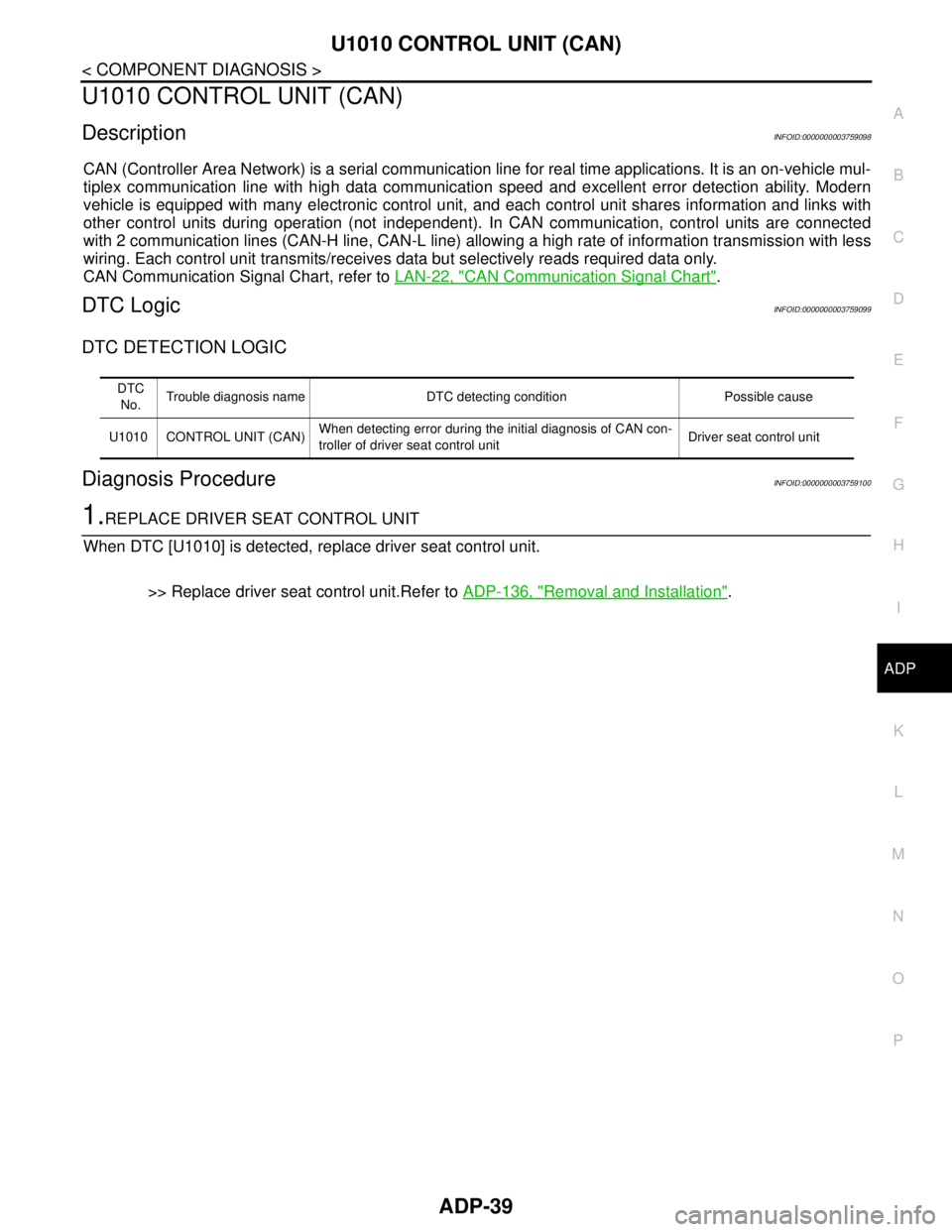
U1010 CONTROL UNIT (CAN)
DescriptionINFOID:0000000003759098
CAN (Controller Area Network) is a serial communication line for real time applications. It is an on-vehicle mul-
tiplex communication line with high data communication speed and excellent error detection ability. Modern
vehicle is equipped with many electronic control unit, and each control unit shares information and links with
other control units during operation (not independent). In CAN communication, control units are connected
with 2 communication lines (CAN-H line, CAN-L line) allowing a high rate of information transmission with less
wiring. Each control unit transmits/receives data but selectively reads required data only.
CAN Communication Signal Chart, refer to LAN-22, "
CAN Communication Signal Chart".
DTC LogicINFOID:0000000003759099
DTC DETECTION LOGIC
Diagnosis ProcedureINFOID:0000000003759100
1.REPLACE DRIVER SEAT CONTROL UNIT
When DTC [U1010] is detected, replace driver seat control unit.
>> Replace driver seat control unit.Refer to ADP-136, "
Removal and Installation".
DTC
No.Trouble diagnosis name DTC detecting condition Possible cause
U1010 CONTROL UNIT (CAN)When detecting error during the initial diagnosis of CAN con-
troller of driver seat control unitDriver seat control unit
Page 115 of 5121

BCM (BODY CONTROL MODULE)
ADP-109
< COMPONENT DIAGNOSIS >
C
D
E
F
G
H
I
K
L
MA
B
ADP
N
O
P
HIGH FLASHER OPERATION
BCM detects the turn signal lamp circuit status by the current value.
BCM increases the turn signal lamp blinking speed if the bulb or harness open is detected with the turn signal
lamp operating.
NOTE:
The blinking speed is normal while activating the hazard warning lamp.
DTC Inspection Priority ChartINFOID:0000000003940048
If some DTCs are displayed at the same time, perform inspections one by one based on the following priority
chart.
B2608: STARTER RELAY Inhibit engine cranking500 ms after the following signal communication status becomes
consistent
Starter motor relay control signal
Starter relay status signal (CAN)
B2609: S/L STATUS Inhibit engine cranking
Inhibit steering lockWhen the following steering lock conditions agree
BCM steering lock control status
Steering lock condition No. 1 signal status
Steering lock condition No. 2 signal status
B260A: IGNITION RELAY Inhibit engine cranking500 ms after the following conditions are fulfilled
IGN relay (IPDM E/R) control signal: OFF (Battery voltage)
Ignition ON signal (CAN to IPDM E/R): OFF (Request signal)
Ignition ON signal (CAN from IPDM E/R): OFF (Condition signal)
B260F: ENG STATE SIG LOSTMaintains the power supply
position attained at the time
of DTC detectionWhen any of the following conditions is fulfilled
Power position changes to ACC
Receives engine status signal (CAN)
B2612: S/L STATUS Inhibit engine cranking
Inhibit steering lockWhen any of the following conditions is fulfilled
Steering lock unit status signal (CAN) is received normally
The BCM steering lock control status matches the steering lock
status recognized by the steering lock unit status signal (CAN
from IPDM E/R)
B2617: STARTER RELAY CIRC Inhibit engine cranking1 second after the starter motor relay control inside BCM becomes
normal
B2618: BCM Inhibit engine cranking1 second after the ignition relay (IPDM E/R) control inside BCM be-
comes normal
B2619: BCM Inhibit engine cranking1 second after the steering lock unit power supply output control in-
side BCM becomes normal
B261E: VEHICLE TYPE Inhibit engine cranking BCM initialization
B26E1: ENG STATE NO RES Inhibit engine crankingWhen any of the following conditions is fulfilled
Power position changes to ACC
Receives engine status signal (CAN)
B26E9: S/L STATUS Inhibit engine cranking
Inhibit steering lockWhen BCM transmits the LOCK request signal to steering lock unit,
and receives LOCK response signal from steering lock unit, the fol-
lowing conditions is fulfilled
Steering condition No. 1 signal: LOCK (0 V)
Steering condition No. 2 signal: LOCK (Battery voltage) Display contents of CONSULT Fail-safe Cancellation
Priority DTC
1 B2562: LOW VOLTAGE
2 U1000: CAN COMM CIRCUIT
U1010: CONTROL UNIT (CAN)
3 B2190: NATS ANTENNA AMP
B2191: DIFFERENCE OF KEY
B2192: ID DISCORD BCM-ECM
B2193: CHAIN OF BCM-ECM
Page 158 of 5121
![NISSAN TEANA 2008 Service Manual AV-14
< FUNCTION DIAGNOSIS >[AUDIO SYSTEM]
AUDIO SYSTEM
Component Parts Location
INFOID:0000000003765590
Component DescriptionINFOID:0000000003765591
1. Front squawker RH 2. Front squawker LH 3. Front](/img/5/57391/w960_57391-157.png "NISSAN TEANA 2008 Service Manual AV-14
< FUNCTION DIAGNOSIS >[AUDIO SYSTEM]
AUDIO SYSTEM
Component Parts Location
INFOID:0000000003765590
Component DescriptionINFOID:0000000003765591
1. Front squawker RH 2. Front squawker LH 3. Front")
AV-14
< FUNCTION DIAGNOSIS >[AUDIO SYSTEM]
AUDIO SYSTEM
Component Parts Location
INFOID:0000000003765590
Component DescriptionINFOID:0000000003765591
1. Front squawker RH 2. Front squawker LH 3. Front door speaker LH
4. Rear door speaker LH 5. Antenna amp. 6. Rear door speaker RH
7. Front door speaker RH 8. Steering switch 9. Audio unit
10. Audio display unit
A. Within rear pillar finisher RH
JPNIA1057ZZ
Part name Description
AUDIO UNIT Has radio function and CD playing function.
Sound signals are output to each speaker.
AUDIO DISPLAY UNIT Display images are controlled by AV communication from audio unit.
FRONT DOOR SPEAKER Outputs sound signals from audio unit.
Outputs sound (mid and low range).
REAR DOOR SPEAKER Outputs sound signals from audio unit.
Outputs sound (mid and low range).
FRONT SQUAWKER Outputs sound signals from audio unit.
Outputs sound (high and mid range).
STEERING SWITCH Steering switch signals (operation signals) are output to audio unit.
ANTENNA AMP. Radio signal received by glass antenna is amplified and transmitted to audio
unit.
Power (antenna amp. ON signal) is supplied from audio unit.
Page 180 of 5121
![NISSAN TEANA 2008 Service Manual AV-36
< PRECAUTION >[AUDIO SYSTEM]
PRECAUTIONS
PRECAUTION
PRECAUTIONS
Precaution for Supplemental Restraint System (SRS) "AIR BAG" and "SEAT BELT
PRE-TENSIONER"
INFOID:0000000003960541
The Supplement](/img/5/57391/w960_57391-179.png "NISSAN TEANA 2008 Service Manual AV-36
< PRECAUTION >[AUDIO SYSTEM]
PRECAUTIONS
PRECAUTION
PRECAUTIONS
Precaution for Supplemental Restraint System (SRS) \"AIR BAG\" and \"SEAT BELT
PRE-TENSIONER\"
INFOID:0000000003960541
The Supplement")
AV-36
< PRECAUTION >[AUDIO SYSTEM]
PRECAUTIONS
PRECAUTION
PRECAUTIONS
Precaution for Supplemental Restraint System (SRS) "AIR BAG" and "SEAT BELT
PRE-TENSIONER"
INFOID:0000000003960541
The Supplemental Restraint System such as “AIR BAG” and “SEAT BELT PRE-TENSIONER”, used along
with a front seat belt, helps to reduce the risk or severity of injury to the driver and front passenger for certain
types of collision. Information necessary to service the system safely is included in the “SRS AIRBAG” and
“SEAT BELT” of this Service Manual.
WARNING:
• To avoid rendering the SRS inoperative, which could increase the risk of personal injury or death in
the event of a collision which would result in air bag inflation, all maintenance must be performed by
an authorized NISSAN/INFINITI dealer.
Improper maintenance, including incorrect removal and installation of the SRS, can lead to personal
injury caused by unintentional activation of the system. For removal of Spiral Cable and Air Bag
Module, see the “SRS AIRBAG”.
Never use electrical test equipment on any circuit related to the SRS unless instructed to in this Ser-
vice Manual. SRS wiring harnesses can be identified by yellow and/or orange harnesses or harness
connectors.
Precaution for Trouble DiagnosisINFOID:0000000003765608
AV COMMUNICATION SYSTEM
Do not apply voltage of 7.0 V or higher to the measurement terminals.
Use the tester with its open terminal voltage at 7.0 V or less.
Turn ignition switch OFF and disconnect the battery cable from the negative terminal before checking the cir-
cuit.
Precaution for Harness RepairINFOID:0000000003765609
AV COMMUNICATION SYSTEM
Solder the repaired parts, and wrap with tape. [Frays of twisted line
must be within 110 mm (4.33 in).]
Do not perform bypass wire connections for the repair parts. (The
spliced wire will become separated and the characteristics of
twisted line will be lost.)
PKIA0306E
PKIA0307E
Page 195 of 5121
![NISSAN TEANA 2008 Service Manual AV
MULTI AV SYSTEM
AV-51
< FUNCTION DIAGNOSIS >[BASE AUDIO AND DISPLAY SYSTEM]
C
D
E
F
G
H
I
J
K
L
MB A
O
P
Component DescriptionINFOID:0000000003882702
Part name Description
AV CONTROL UNIT It is th](/img/5/57391/w960_57391-194.png "NISSAN TEANA 2008 Service Manual AV
MULTI AV SYSTEM
AV-51
< FUNCTION DIAGNOSIS >[BASE AUDIO AND DISPLAY SYSTEM]
C
D
E
F
G
H
I
J
K
L
MB A
O
P
Component DescriptionINFOID:0000000003882702
Part name Description
AV CONTROL UNIT It is th")
AV
MULTI AV SYSTEM
AV-51
< FUNCTION DIAGNOSIS >[BASE AUDIO AND DISPLAY SYSTEM]
C
D
E
F
G
H
I
J
K
L
MB A
O
P
Component DescriptionINFOID:0000000003882702
Part name Description
AV CONTROL UNIT It is the master unit of the MULTI AV system, and it is connected to each control
unit by communication. It operates each system according to communication
signals from the AV control unit.
AV control unit includes audio function and vehicle information function.
It is connected to ECM and combination meter via CAN communication to ob-
tain necessary information for the vehicle information function.
It is connected to BCM via CAN communication transmitting/receiving for the
vehicle settings function.
AUX image signal is input from auxiliary jacks.
Camera image signal is input from camera control unit.
Composite image (AUX and camera images) signal is output to display unit.
AUX sound signal is input from the auxiliary jacks.
Power (signal VCC and inverter VCC) is transmitted to front display unit.
DISPLAY UNIT Display image is controlled by the serial communication from AV control unit.
It receives the power (signal VCC and inverter VCC) from the AV control unit
and operates.
RGB image signal is input from AV control unit (RGB, RGB area and RGB syn-
chronizing).
Composite image (AUX and camera images) signal is input from AV control
unit.
Synchronize signal (HP, VP) is output to AV control unit.
FRONT SPEAKER Outputs sound signal from front speaker.
Outputs sound (mid and low range).
REAR SPEAKER Outputs sound signal from rear speaker.
Outputs sound (mid and low range).
FRONT SQUAWKER Outputs sound signal from front squawker.
Outputs sound (high and mid range).
MULTIFUNCTION SWITCH Operation panel is equipped with the centralized switch where camera, audio
and auxiliary input operations are integrated.
The multifunction switch is connected to the preset switch by wiring harness,
and it transmits the operation signal to the preset switch.
PRESET SWITCH Operation panel is equipped with the centralized switch where audio and air
conditioner operations are integrated.
The preset switch is connected via AV communication, and it transmits the op-
eration signals of the preset switch and multifunction switch.
The disk ejection operating signal is performed by wiring harness.
CAMERA CONTROL UNIT Camera image signal is input from rear view camera. Camera image signal
output to AV control unit.
Power supply is transmitted to rear view camera.
AV control unit recognizes the presence of camera system with camera con-
nection recognition signal.
Camera control unit is connected via AV communication.
REAR VIEW CAMERA The image of vehicle rear view is transmitted to camera control unit.
It receives the power supply from the camera control unit and operates.
STEERING ANGLE SENSOR Sensor signal (steering angle) is transmitted to camera control unit.
STEERING SWITCH The operations of audio, etc. can be performed.
Steering switch signal (operation signal) is output to AV control unit.
AUXILIARY INPUT JACKS The image signal of the auxiliary input is output via the AV control unit to the
display unit.
The sound signal of the auxiliary input is output via the AV control unit to the
each speaker.
Page 199 of 5121
![NISSAN TEANA 2008 Service Manual AV
AUDIO SYSTEM
AV-55
< FUNCTION DIAGNOSIS >[BASE AUDIO AND DISPLAY SYSTEM]
C
D
E
F
G
H
I
J
K
L
MB A
O
P
Component DescriptionINFOID:0000000003791248
Part name Description
AV CONTROL UNIT The AM/FM r](/img/5/57391/w960_57391-198.png "NISSAN TEANA 2008 Service Manual AV
AUDIO SYSTEM
AV-55
< FUNCTION DIAGNOSIS >[BASE AUDIO AND DISPLAY SYSTEM]
C
D
E
F
G
H
I
J
K
L
MB A
O
P
Component DescriptionINFOID:0000000003791248
Part name Description
AV CONTROL UNIT The AM/FM r")
AV
AUDIO SYSTEM
AV-55
< FUNCTION DIAGNOSIS >[BASE AUDIO AND DISPLAY SYSTEM]
C
D
E
F
G
H
I
J
K
L
MB A
O
P
Component DescriptionINFOID:0000000003791248
Part name Description
AV CONTROL UNIT The AM/FM receiving function and the CD playing function are equipped.
Sound signal is transmitted to each speaker.
DISPLAY UNIT Display image is controlled by the serial communication from AV control unit.
RGB image signal (audio operation condition) is input from AV control unit.
FRONT SPEAKER Outputs sound signal from front speaker.
Outputs sound (mid and low range).
REAR SPEAKER Outputs sound signal from rear speaker.
Outputs sound (mid and low range).
FRONT SQUAWKER Outputs sound signal from front squawker.
Outputs sound (high and mid range).
MULTIFUNCTION SWITCH Each audio operation can be operated.
The multifunction switch is connected to the preset switch by wiring harness,
and it transmits the operation signal to the preset switch.
PRESET SWITCH Each audio operation can be operated.
The preset switch is connected via AV communication, and it transmits the op-
eration signals of the preset switch and multifunction switch.
The disk ejection operating signal is performed by hard-wire.
STEERING SWITCH Each audio operation can be operated.
Steering switch signal (operation signal) is output to AV control unit.
REAR CONTROL SWITCH Each audio operation can be operated.
The rear control switch is connected via AV communication, and it transmits
the operation signals of the rear control switch.
ANTENNA AMP. Radio signal received by glass antenna is amplified and transmitted to AV con-
trol unit.
Power (antenna amp. ON signal) is supplied from AV control unit.
Page 216 of 5121
![NISSAN TEANA 2008 Service Manual AV-72
< COMPONENT DIAGNOSIS >[BASE AUDIO AND DISPLAY SYSTEM]
U1000 CAN COMM CIRCUIT
COMPONENT DIAGNOSIS
U1000 CAN COMM CIRCUIT
DescriptionINFOID:0000000003882713
CAN (Controller Area Network) is a ser](/img/5/57391/w960_57391-215.png "NISSAN TEANA 2008 Service Manual AV-72
< COMPONENT DIAGNOSIS >[BASE AUDIO AND DISPLAY SYSTEM]
U1000 CAN COMM CIRCUIT
COMPONENT DIAGNOSIS
U1000 CAN COMM CIRCUIT
DescriptionINFOID:0000000003882713
CAN (Controller Area Network) is a ser")
AV-72
< COMPONENT DIAGNOSIS >[BASE AUDIO AND DISPLAY SYSTEM]
U1000 CAN COMM CIRCUIT
COMPONENT DIAGNOSIS
U1000 CAN COMM CIRCUIT
DescriptionINFOID:0000000003882713
CAN (Controller Area Network) is a serial communication line for real time application. It is an on-vehicle mul-
tiplex communication line with high data communication speed and excellent error detection ability. Many elec-
tronic control units are equipped onto a vehicle, and each control unit shares information and links with other
control units during operation (not independent). In CAN communication, control units are connected with 2
communication lines (CAN-H, CAN-L) allowing a high rate of information transmission with less wiring. Each
control unit transmits/receives data but selectively reads required data only.
CAN Communication Signal Chart. Refer to LAN-22, "
CAN Communication Signal Chart".
DTC LogicINFOID:0000000003882714
DTC DETECTION LOGIC
Diagnosis ProcedureINFOID:0000000003882715
1.PERFORM SELF DIAGNOSTIC
1. Turn ignition switch ON and wait for 2 seconds or more.
2. Check “Self Diagnostic Result” of “MULTI AV”.
Is
“CAN COMM CIRCUIT” displayed?
YES >> Refer to “LAN system”. Refer to LAN-14, "Trouble Diagnosis Flow Chart".
NO >> Refer to GI section. Refer to GI-35, "
Intermittent Incident".
DTCDisplay contents of CON-
SULT-IIIDiagnostic item is detected when... Probable malfunction location
U1000 CAN COMM CIRCUITWhen AV control unit is not transmitting or re-
ceiving CAN communication signal for 2 sec-
onds or more.CAN communication system
Page 311 of 5121
![NISSAN TEANA 2008 Service Manual AV
NORMAL OPERATING CONDITION
AV-167
< SYMPTOM DIAGNOSIS >[BASE AUDIO AND DISPLAY SYSTEM]
C
D
E
F
G
H
I
J
K
L
MB A
O
P
NORMAL OPERATING CONDITION
DescriptionINFOID:0000000003882786
BASIC OPERATIONS
RE](/img/5/57391/w960_57391-310.png "NISSAN TEANA 2008 Service Manual AV
NORMAL OPERATING CONDITION
AV-167
< SYMPTOM DIAGNOSIS >[BASE AUDIO AND DISPLAY SYSTEM]
C
D
E
F
G
H
I
J
K
L
MB A
O
P
NORMAL OPERATING CONDITION
DescriptionINFOID:0000000003882786
BASIC OPERATIONS
RE")
AV
NORMAL OPERATING CONDITION
AV-167
< SYMPTOM DIAGNOSIS >[BASE AUDIO AND DISPLAY SYSTEM]
C
D
E
F
G
H
I
J
K
L
MB A
O
P
NORMAL OPERATING CONDITION
DescriptionINFOID:0000000003882786
BASIC OPERATIONS
RELATED TO AUDIO
The majority of the audio malfunctions are the result of outside causes (bad CD/cassette, electromagnetic
interference, etc.). Check the symptoms below to diagnose the malfunction.
The vehicle itself can be a source of noise if noise prevention parts or electrical equipment is malfunctioning.
Check if noise is caused and/or changed by engine speed, ignition switch turned to each position, and oper-
ation of each piece of electrical equipment, and then determine the cause.
NOTE:
CD-R is not guaranteed to play because they can contain compressed audio (MP3, WMA) or could be incor-
rectly mastered by the customer on a computer.
Check if the CDs carry the Compact Disc Logo. If not, the disc is not mastered to the red book Compact Disc
Standard and may not play.
Symptom Possible cause Possible solution
No image is displayed.The brightness is at the lowest setting. Adjust the brightness of the display.
The system in the video mode. Push
The display is turned off. Push
The screen is too dim. The move-
ment is slow.The temperature in the interior of the vehicle is low. Wait until the interior of the vehicle has
warmed up.
Some pixels in the display are dark-
er or brighter than others.This condition is an inherent characteristic of liquid
crystal displays.This is not a malfunction.
Some menu items cannot be se-
lected.Some menu items become unavailable while the ve-
hicle is driven.Park the vehicle in a safe location, and
then operate the multi AV system.
Symptom Cause and Counter measure
Cannot playCheck if the CD was inserted correctly.
Check if the CD is scratched or dirty.
Check if there is condensation inside the player, and if there is, wait until the condensation is gone
(about 1 hour) before using the player.
If there is a temperature increase error, the player will play correctly after it returns to the normal
temperature.
If there is a mixture of music CD files (CD-DA data) and MP3/WMA files on a CD, only the music
CD files (CD-DA data) will be played.
Files with extensions other than “.MP3”, “.WMA”, “.mp3”, or “.wma” cannot be played. In addition,
the character codes and number of characters for folder names and file names should be in com-
pliance with the specifications.
Check if the disc or the file is generated in an irregular format, This may occur depending on the
variation or the setting of MP3/WMA writing applications or other text editing applications.
Check if the finalization process, such as session close and disc close, is done for the disc.
Check if the CD is protected by copyright.
Poor sound quality Check if the CD is scratched or dirty.
It takes a relatively long time before
the music starts playing.If there are many folder or file levels on the MP3/WMA CD, or if it is a multisession disc, some
time may be required before the music starts playing.
Music cuts off or skipsThe writing software and hardware combination might not match, or the writing speed, writing
depth, writing width might not match the specifications. Try using the slowest writing speed.
Skipping with high bit rate files Skipping may occur with large quantities if data such as for high bit rate data.
Page 313 of 5121
![NISSAN TEANA 2008 Service Manual AV
PRECAUTIONS
AV-169
< PRECAUTION >[BASE AUDIO AND DISPLAY SYSTEM]
C
D
E
F
G
H
I
J
K
L
MB A
O
P
PRECAUTION
PRECAUTIONS
Precaution for Supplemental Restraint System (SRS) "AIR BAG" and "SEAT BELT
PRE](/img/5/57391/w960_57391-312.png "NISSAN TEANA 2008 Service Manual AV
PRECAUTIONS
AV-169
< PRECAUTION >[BASE AUDIO AND DISPLAY SYSTEM]
C
D
E
F
G
H
I
J
K
L
MB A
O
P
PRECAUTION
PRECAUTIONS
Precaution for Supplemental Restraint System (SRS) \"AIR BAG\" and \"SEAT BELT
PRE")
AV
PRECAUTIONS
AV-169
< PRECAUTION >[BASE AUDIO AND DISPLAY SYSTEM]
C
D
E
F
G
H
I
J
K
L
MB A
O
P
PRECAUTION
PRECAUTIONS
Precaution for Supplemental Restraint System (SRS) "AIR BAG" and "SEAT BELT
PRE-TENSIONER"
INFOID:0000000003960542
The Supplemental Restraint System such as “AIR BAG” and “SEAT BELT PRE-TENSIONER”, used along
with a front seat belt, helps to reduce the risk or severity of injury to the driver and front passenger for certain
types of collision. Information necessary to service the system safely is included in the “SRS AIRBAG” and
“SEAT BELT” of this Service Manual.
WARNING:
To avoid rendering the SRS inoperative, which could increase the risk of personal injury or death in
the event of a collision which would result in air bag inflation, all maintenance must be performed by
an authorized NISSAN/INFINITI dealer.
Improper maintenance, including incorrect removal and installation of the SRS, can lead to personal
injury caused by unintentional activation of the system. For removal of Spiral Cable and Air Bag
Module, see the “SRS AIRBAG”.
Never use electrical test equipment on any circuit related to the SRS unless instructed to in this Ser-
vice Manual. SRS wiring harnesses can be identified by yellow and/or orange harnesses or harness
connectors.
Precaution for Trouble DiagnosisINFOID:0000000003882788
AV COMMUNICATION SYSTEM
Do not apply voltage of 7.0 V or higher to the measurement terminals.
Use the tester with its open terminal voltage being 7.0 V or less.
Be sure to turn ignition switch OFF and disconnect the battery cable from the negative terminal before
checking the circuit.
Precaution for Harness RepairINFOID:0000000003882789
AV COMMUNICATION SYSTEM
Solder the repaired parts, and wrap with tape. [Frays of twisted line
must be within 110 mm (4.33 in).]
Do not perform bypass wire connections for the repair parts. (The
spliced wire will become separated and the characteristics of
twisted line will be lost.)
PKIA0306E
PKIA0307E