service indicator NISSAN TEANA 2008 Service Manual
[x] Cancel search | Manufacturer: NISSAN, Model Year: 2008, Model line: TEANA, Model: NISSAN TEANA 2008Pages: 5121, PDF Size: 69.03 MB
Page 1 of 5121

MODEL J32 SERIES
© 2008 NISSAN INTERNATIONAL SA
Allrightsreserved.NopartofthisElectronicServiceManualmaybereproducedorstoredinaretrievalsystem,ortransmittedinanyform,or by any means, electronic, mechanical, photocopying, recording or otherwise, without the prior written permission of Nissan InternationalSA, Switzerland.
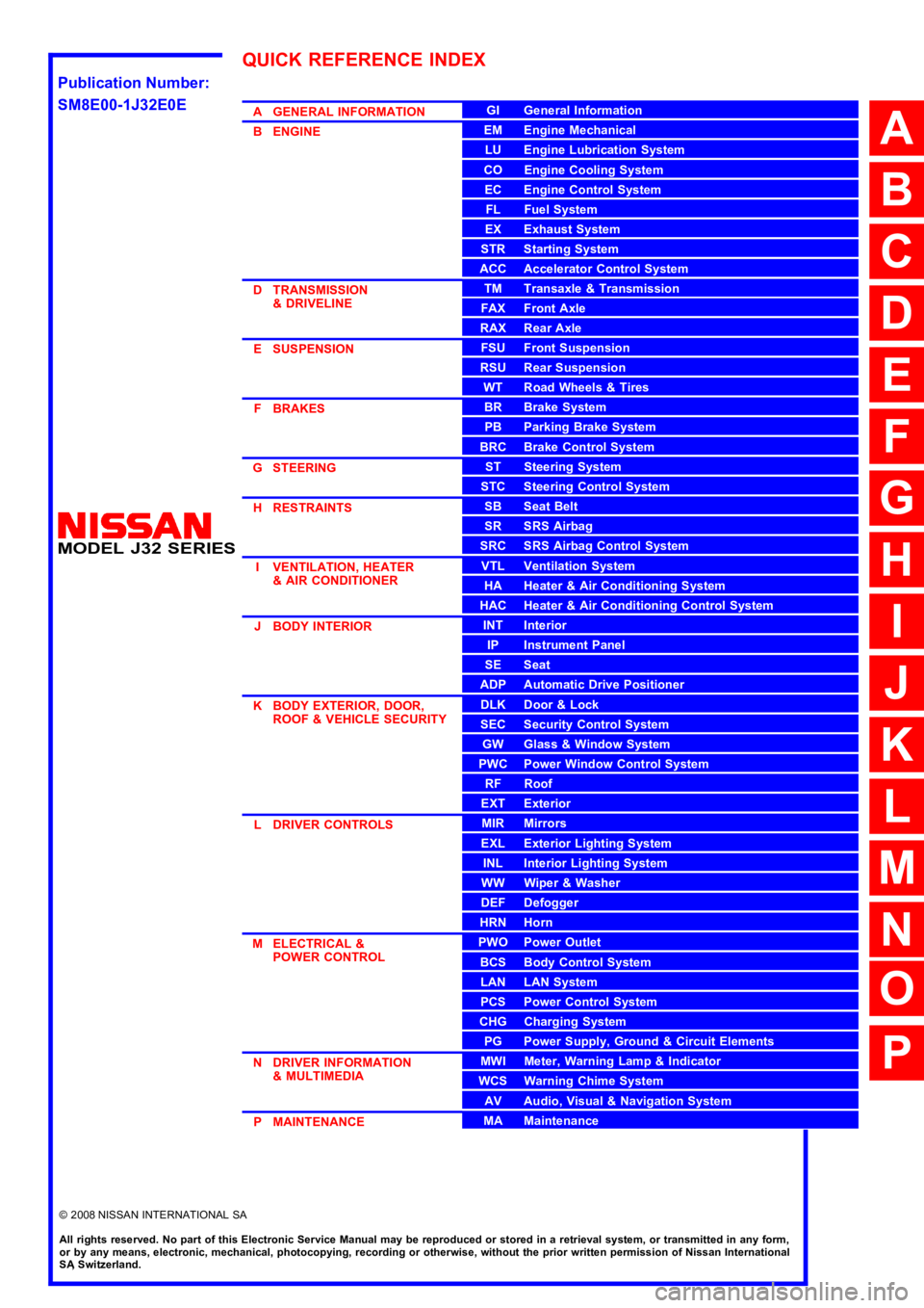
AGENERALINFORMATION
BENGINE
DTRANSMISSION&DRIVELINE
ESUSPENSION
FBRAKES
GSTEERING
HRESTRAINTS
IVENTILATION,HEATER&AIRCONDITIONER
JBODYINTERIOR
KBODYEXTERIOR,DOOR,ROOF&VEHICLESECURITY
LDRIVERCONTROLS
MELECTRICAL&POWERCONTROL
NDRIVERINFORMATION&MULTIMEDIA
PMAINTENANCE
GIGeneralInformation
EMEngineMechanical
LUEngineLubricationSystem
COEngineCoolingSystem
ECEngineControlSystem
FLFuelSystem
EXExhaustSystem
STRStartingSystem
ACCAcceleratorControlSystem
TMTransaxle &Transmission
FAXFrontAxle
RAXRearAxle
FSUFrontSuspension
RSURearSuspension
WTRoadWheels &Tires
BRBrakeSystem
PBParkingBrakeSystem
BRCBrakeControlSystem
STSteeringSystem
STCSteeringControlSystem
SBSeatBelt
SRSRSAirbag
SRCSRSAirbagControlSystem
VTLVentilationSystem
HAHeater &AirConditioningSystem
HACHeater &AirConditioningControlSystem
INTInterior
IPInstrumentPanel
SESeat
ADPAutomaticDrivePositioner
DLKDoor &Lock
SECSecurityControlSystem
GWGlass &WindowSystem
PWCPowerWindowControlSystem
RFRoof
EXTExterior
MIRMirrors
EXLExteriorLightingSystem
INLInteriorLightingSystem
WWWiper &Washer
DEFDefogger
HRNHorn
PWOPowerOutlet
BCSBodyControlSystem
LANLANSystem
PCSPowerControlSystem
CHGChargingSystem
PGPowerSupply,Ground&CircuitElements
MWIMeter,WarningLamp&Indicator
WCSWarningChimeSystem
AVAudio,Visual&NavigationSystem
MAMaintenance
QUICKREFERENCEINDEX
A
B
C
D
E
F
G
H
I
J
K
L
M
N
O
P
M
Publication Number:
SM8E00-1J32E0E
Page 840 of 5121

BCS
DIAGNOSIS SYSTEM (BCM)
BCS-23
< FUNCTION DIAGNOSIS >
C
D
E
F
G
H
I
J
K
L B A
O
P N
WIPER
WIPER : CONSULT-III Function (BCM - WIPER)INFOID:0000000003897063
WORK SUPPORT
*:Factory setting
NOTE:
When performed “RESET SETTING VALUE” on “Work Support (BCM - BCM)”, set “WIPER SPEED SETTING” on “Work Support (BCM
-WIPER)” to “On”.
DATA MONITOR
ACTIVE TEST
RR FOG LAMPOn Outputs the voltage to turn the rear fog lamp ON.
Transmits the rear fog lamp status signal to the combination meter with
CAN communication to turn the rear fog lamp indicator lamp ON.
Off Stops the voltage to turn the rear fog lamp OFF.
Stops the rear fog lamp status signal transmission.
DAYTIME RUNNING LIGHTOn
NOTE:
The item is indicated, but cannot be tested.
Off
CORNERING LAMPRH
NOTE:
The item is indicated, but cannot be tested. LH
Off
ILL DIM SIGNALOn
NOTE:
The item is indicated, but cannot be tested.
Off Test item Operation Description
Service item Setting item Description
WIPER SPEED
SETTINGOn*With vehicle speed
(Front wiper intermittent time linked with the vehicle speed and wiper intermittent dial position)
OffWithout vehicle speed
(Front wiper intermittent time linked with the wiper intermittent dial position)
Monitor Item
[Unit]Description
PUSH SW
[Off/On]The switch status input from push-button ignition switch.
VEH SPEED 1
[km/h]Displays the value of the vehicle speed signal received from combination meter with CAN communication.
FR WIPER HI
[Off/On]
Status of each switch judged by BCM using the combination switch reading function FR WIPER LOW
[Off/On]
FR WASHER SW
[Off/On]
FR WIPER INT
[Off/On]
FR WIPER STOP
[Off/On]Displays the status of the front wiper stop position signal received from IPDM E/R with CAN communication.
INT VOLUME
[1 − 7] Status of each switch judged by BCM using the combination switch reading function
H/L WASH SW
[Off/On]Status of the switch input from headlamp washer switch
Page 846 of 5121

BCS
DIAGNOSIS SYSTEM (BCM)
BCS-29
< FUNCTION DIAGNOSIS >
C
D
E
F
G
H
I
J
K
L B A
O
P N
When performed “RESET SETTING VALUE” on “Work Support (BCM - BCM)”, set “WIPER SPEED SETTING” on “Work Support (BCM
- WIPER)” to “On”.
IMMU
IMMU : CONSULT-III Function (BCM - IMMU)INFOID:0000000003897057
APPLICATION ITEM
CONSULT-III performs the following functions via CAN communication with BCM.
DATA MONITOR
ACTIVE TEST
BATTERY SAVER
BATTERY SAVER : CONSULT-III Function (BCM - BATTERY SAVER)INFOID:0000000003897060
WORK SUPPORT
*: Factory setting
DATA MONITOR
Diagnosis mode Function Description
DATA MONITOR The BCM input/output signals are displayed.
ACTIVE TEST The signals used to activate each device are forcibly supplied from BCM.
Monitor item Content
CONFRM ID ALL
Indicates [YET] at all time.
Switches to [DONE] when a registered Intelligent Key is inserted into the key slot. CONFIRM ID4
CONFIRM ID3
CONFIRM ID2
CONFIRM ID1
TP 4
Indicates the number of ID which has been registered. TP 3
TP 2
TP 1
PUSH SW Indicates [ON/OFF] condition of push-button ignition switch.
KEY SW -SLOT Indicates [ON/OFF] condition of key slot.
Test item Description
THEFT INDThis test is able to check security indicator lamp operation.
The lamp will be turned on when “ON” on CONSULT-III screen touched.
Service item Setting item Setting
BATTERY SAVER SETOn* With the exterior lamp battery saver function
Off Without the exterior lamp battery saver function
ROOM LAMP BAT SAV SETOn* With the interior room lamp battery saver function
Off Without the interior room lamp battery saver function
ROOM LAMP TIMER SETMODE 1* 30 min.
Sets the interior room lamp battery saver timer operating
time.
MODE 2 60 min.
Page 1472 of 5121
![NISSAN TEANA 2008 Service Manual INSPECTION AND ADJUSTMENT
EC-11
< BASIC INSPECTION >[VQ25DE, VQ35DE]
C
D
E
F
G
H
I
J
K
L
MA
EC
N
P O
INSPECTION AND ADJUSTMENT
BASIC INSPECTION
BASIC INSPECTION : Special Repair RequirementINFOID:0000 NISSAN TEANA 2008 Service Manual INSPECTION AND ADJUSTMENT
EC-11
< BASIC INSPECTION >[VQ25DE, VQ35DE]
C
D
E
F
G
H
I
J
K
L
MA
EC
N
P O
INSPECTION AND ADJUSTMENT
BASIC INSPECTION
BASIC INSPECTION : Special Repair RequirementINFOID:0000](/img/5/57391/w960_57391-1471.png)
INSPECTION AND ADJUSTMENT
EC-11
< BASIC INSPECTION >[VQ25DE, VQ35DE]
C
D
E
F
G
H
I
J
K
L
MA
EC
N
P O
INSPECTION AND ADJUSTMENT
BASIC INSPECTION
BASIC INSPECTION : Special Repair RequirementINFOID:0000000003856444
1.INSPECTION START
1. Check service records for any recent repairs that may indicate a related malfunction, or a current need for
scheduled maintenance.
2. Open engine hood and check the following:
- Harness connectors for improper connections
- Wiring harness for improper connections, pinches and cut
- Vacuum hoses for splits, kinks and improper connections
- Hoses and ducts for leaks
- Air cleaner clogging
- Gasket
3. Confirm that electrical or mechanical loads are not applied.
- Head lamp switch is OFF.
- Air conditioner switch is OFF.
- Rear window defogger switch is OFF.
- Steering wheel is in the straight-ahead position, etc.
4. Start engine and warm it up until engine coolant temperature
indicator points the middle of gauge.
Ensure engine stays below 1,000 rpm.
5. Run engine at about 2,000 rpm for about 2 minutes under no
load.
6. Check that no DTC is displayed with CONSULT-III or GST.
Are any DTCs detected?
YES >> GO TO 2.
NO >> GO TO 3.
2.REPAIR OR REPLACE
Repair or replace components as necessary according to corresponding Diagnostic Procedure.
>> GO TO 3
3.CHECK TARGET IDLE SPEED
1. Run engine at about 2,000 rpm for about 2 minutes under no load.
SEF983U
SEF976U
SEF977U
Page 1563 of 5121
![NISSAN TEANA 2008 Service Manual EC-102
< FUNCTION DIAGNOSIS >[VQ25DE, VQ35DE]
ON BOARD DIAGNOSTIC (OBD) SYSTEM
ON BOARD DIAGNOSTIC (OBD) SYSTEM
Diagnosis DescriptionINFOID:0000000003856502
INTRODUCTION
The ECM has an on board diagno NISSAN TEANA 2008 Service Manual EC-102
< FUNCTION DIAGNOSIS >[VQ25DE, VQ35DE]
ON BOARD DIAGNOSTIC (OBD) SYSTEM
ON BOARD DIAGNOSTIC (OBD) SYSTEM
Diagnosis DescriptionINFOID:0000000003856502
INTRODUCTION
The ECM has an on board diagno](/img/5/57391/w960_57391-1562.png)
EC-102
< FUNCTION DIAGNOSIS >[VQ25DE, VQ35DE]
ON BOARD DIAGNOSTIC (OBD) SYSTEM
ON BOARD DIAGNOSTIC (OBD) SYSTEM
Diagnosis DescriptionINFOID:0000000003856502
INTRODUCTION
The ECM has an on board diagnostic system, which detects malfunctions related to engine sensors or actua-
tors. The ECM also records various emission-related diagnostic information including:
The above information can be checked using procedures listed in the table below.
×: Applicable —: Not applicable
*: When DTC and 1st trip DTC simultaneously appear on the display, they cannot be clearly distinguished from each other.
The malfunction indicator MI on the instrument panel illuminates when the same malfunction is detected in two
consecutive trips (Two trip detection logic), or when the ECM enters fail-safe mode. (Refer to EC-386, "
Fail
safe".)
TWO TRIP DETECTION LOGIC
When a malfunction is detected for the first time, 1st trip DTC and 1st trip Freeze Frame data are stored in the
ECM memory. The MI will not illuminate at this stage. <1st trip>
If the same malfunction is detected again during the next drive, the DTC and Freeze Frame data are stored in
the ECM memory, and the MI illuminates. The MI illuminates at the same time the DTC is stored. <2nd trip>
The “trip” in the “Two Trip Detection Logic” means a driving mode in which self-diagnosis is performed during
vehicle operation. Specific on board diagnostic items will cause the ECM to illuminate or blink the MI, and
store DTC and Freeze Frame data, even in the 1st trip, as shown below.
×: Applicable —: Not applicable
DTC AND FREEZE FRAME DATA
DTC and 1st Trip DTC
Emission-related diagnostic information Diagnostic service
Diagnostic Trouble Code (DTC) Service $03 of ISO 15031-5
Freeze Frame data Service $02 of ISO 15031-5
System Readiness Test (SRT) code Service $01 of ISO 15031-5
1st Trip Diagnostic Trouble Code (1st Trip DTC) Service $07 of ISO 15031-5
1st Trip Freeze Frame data —
Test values and Test limits Service $06 of ISO 15031-5
Calibration ID Service $09 of ISO 15031-5
DTC 1st trip DTCFreeze
Frame data1st trip Freeze
Frame dataSRT code SRT status Test value
CONSULT-III×× × × × ×—
GST×× ×—×××
ECM××*— — —×—
ItemsMI DTC 1st trip DTC
1st trip 2nd trip
1st trip
displaying2nd trip
displaying1st trip
displaying2nd trip
display-
ing BlinkingIlluminat-
edBlinkingIlluminat-
ed
Misfire (Possible three way catalyst
damage) — DTC: P0300 - P0306 is
being detected×———— —×—
Misfire (Possible three way catalyst
damage) — DTC: P0300 - P0306 is
being detected——×——×——
One trip detection diagnoses (Re-
fer to EC-389, "
DTCIndex".)—×——×———
Except above — — —×—××—
Page 1568 of 5121
![NISSAN TEANA 2008 Service Manual ON BOARD DIAGNOSTIC (OBD) SYSTEM
EC-107
< FUNCTION DIAGNOSIS >[VQ25DE, VQ35DE]
C
D
E
F
G
H
I
J
K
L
MA
EC
N
P O How to Display SRT Status
WITH CONSULT-III
Selecting “SRT STATUS” in “DTC CONFIRMAT NISSAN TEANA 2008 Service Manual ON BOARD DIAGNOSTIC (OBD) SYSTEM
EC-107
< FUNCTION DIAGNOSIS >[VQ25DE, VQ35DE]
C
D
E
F
G
H
I
J
K
L
MA
EC
N
P O How to Display SRT Status
WITH CONSULT-III
Selecting “SRT STATUS” in “DTC CONFIRMAT](/img/5/57391/w960_57391-1567.png)
ON BOARD DIAGNOSTIC (OBD) SYSTEM
EC-107
< FUNCTION DIAGNOSIS >[VQ25DE, VQ35DE]
C
D
E
F
G
H
I
J
K
L
MA
EC
N
P O How to Display SRT Status
WITH CONSULT-III
Selecting “SRT STATUS” in “DTC CONFIRMATION” mode with CONSULT-III.
For items whose SRT codes are set, “CMPLT” is displayed on the CONSULT-III screen; for items whose SRT
codes are not set, “INCMP” is displayed.
NOTE:
Though displayed on the CONSULT-III screen, “HO2S HTR” is not SRT item.
WITH GST
Selecting Service $01 with GST (Generic Scan Tool)
MALFUNCTION INDICATOR (MI)
Description
The MI is located on the instrument panel.
1. The MI will illuminate when the ignition switch is turned ON with-
out the engine running. This is a bulb check.
If the MI does not illuminate, check MI circuit. Refer to EC-346,
"Component Function Check".
2. When the engine is started, the MI should go off.
If the MI remains on, the on board diagnostic system has
detected an engine system malfunction.
On Board Diagnostic System Function
The on board diagnostic system has the following three functions.
Diagnostic Test Mode I — Bulb Check
In this mode, the MI on the instrument panel should stay ON. If it remains OFF, check MI circuit. Refer to EC-
346, "Component Function Check".
Diagnostic Test Mode I — Malfunction Warning
SAT652J
Diagnostic Test
ModeKEY and ENG.
Sta tusFunction Explanation of Function
Mode I Ignition switch in
ON position
Engine stoppedBULB CHECK This function checks the MI bulb for damage (blown, open
circuit, etc.).
If the MI does not come on, check MI circuit.
Engine running MALFUNCTION
WARNINGWhen a malfunction is detected twice in two consecutive
driving cycles (two trip detection logic), the MI will illuminate
to inform the driver that a malfunction has been detected.
The following malfunctions will illuminate or blink the MI in
the 1st trip.
Misfire (Possible three way catalyst damage)
One trip detection diagnoses
Mode II Ignition switch in
ON position
Engine stoppedSELF-DIAGNOSTIC
RESULTSThis function allows DTCs and 1st trip DTCs to be read.
Page 1866 of 5121
![NISSAN TEANA 2008 Service Manual PRECAUTIONS
EC-405
< PRECAUTION >[VQ25DE, VQ35DE]
C
D
E
F
G
H
I
J
K
L
MA
EC
N
P O
PRECAUTION
PRECAUTIONS
Precaution for Supplemental Restraint System (SRS) "AIR BAG" and "SEAT BELT
PRE-TENSIONER"
INF NISSAN TEANA 2008 Service Manual PRECAUTIONS
EC-405
< PRECAUTION >[VQ25DE, VQ35DE]
C
D
E
F
G
H
I
J
K
L
MA
EC
N
P O
PRECAUTION
PRECAUTIONS
Precaution for Supplemental Restraint System (SRS) "AIR BAG" and "SEAT BELT
PRE-TENSIONER"
INF](/img/5/57391/w960_57391-1865.png)
PRECAUTIONS
EC-405
< PRECAUTION >[VQ25DE, VQ35DE]
C
D
E
F
G
H
I
J
K
L
MA
EC
N
P O
PRECAUTION
PRECAUTIONS
Precaution for Supplemental Restraint System (SRS) "AIR BAG" and "SEAT BELT
PRE-TENSIONER"
INFOID:0000000003960684
The Supplemental Restraint System such as “AIR BAG” and “SEAT BELT PRE-TENSIONER”, used along
with a front seat belt, helps to reduce the risk or severity of injury to the driver and front passenger for certain
types of collision. Information necessary to service the system safely is included in the “SRS AIRBAG” and
“SEAT BELT” of this Service Manual.
WARNING:
To avoid rendering the SRS inoperative, which could increase the risk of personal injury or death in
the event of a collision which would result in air bag inflation, all maintenance must be performed by
an authorized NISSAN/INFINITI dealer.
Improper maintenance, including incorrect removal and installation of the SRS, can lead to personal
injury caused by unintentional activation of the system. For removal of Spiral Cable and Air Bag
Module, see the “SRS AIRBAG”.
Never use electrical test equipment on any circuit related to the SRS unless instructed to in this Ser-
vice Manual. SRS wiring harnesses can be identified by yellow and/or orange harnesses or harness
connectors.
Precautions For Xenon Headlamp ServiceINFOID:0000000003856878
WARNING:
Comply with the following warnings to prevent any serious accident.
Disconnect the battery cable (negative terminal) or the power supply fuse before installing, remov-
ing, or touching the xenon headlamp (bulb included). The xenon headlamp contains high-voltage
generated parts.
Never work with wet hands.
Check the xenon headlamp ON-OFF status after assembling it to the vehicle. Never turn the xenon
headlamp ON in other conditions. Connect the power supply to the vehicle-side connector.
(Turning it ON outside the lamp case may cause fire or visual impairments.)
Never touch the bulb glass immediately after turning it OFF. It is extremely hot.
CAUTION:
Comply with the following cautions to prevent any error and malfunction.
Install the xenon bulb securely. (Insufficient bulb socket installation may melt the bulb, the connec-
tor, the housing, etc. by high-voltage leakage or corona discharge.)
Never perform HID circuit inspection with a tester.
Never touch the xenon bulb glass with hands. Never put oil and grease on it.
Dispose of the used xenon bulb after packing it in thick vinyl without breaking it.
Never wipe out dirt and contamination with organic solvent (thinner, gasoline, etc.).
Precaution for Procedure without Cowl Top CoverINFOID:0000000003856879
When performing the procedure after removing cowl top cover, cover
the lower end of windshield with urethane, etc.
On Board Diagnostic (OBD) System of Engine and CVTINFOID:0000000003856880
The ECM has an on board diagnostic system. It will illuminate the malfunction indicator MI to warn the driver of
a malfunction causing emission deterioration.
PIIB3706J
Page 1994 of 5121

CYLINDER BLOCK
EM-119
< DISASSEMBLY AND ASSEMBLY >
C
D
E
F
G
H
I
J
K
L
MA
EM
N
P O
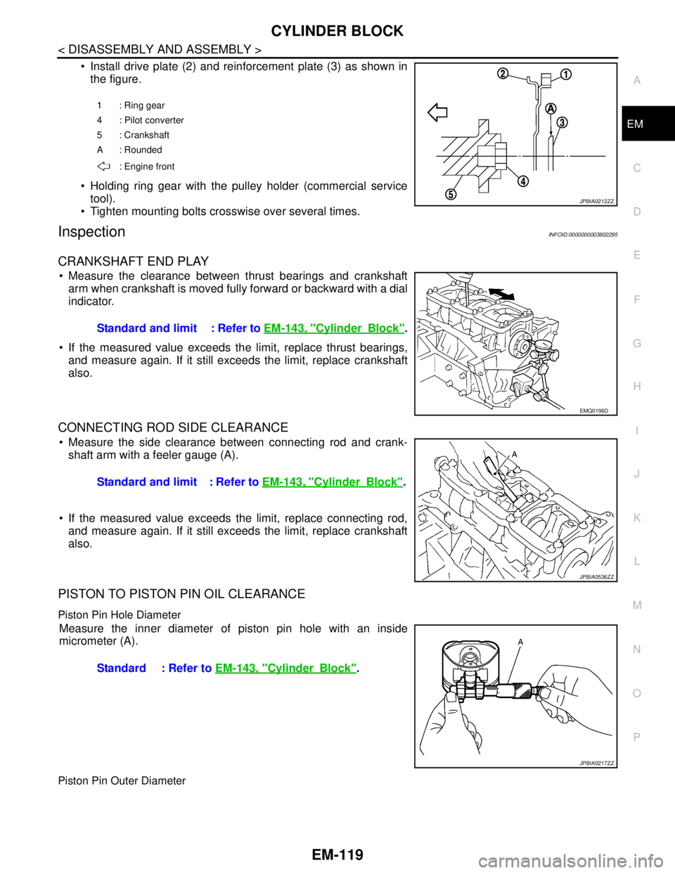
Install drive plate (2) and reinforcement plate (3) as shown in
the figure.
Holding ring gear with the pulley holder (commercial service
tool).
Tighten mounting bolts crosswise over several times.
InspectionINFOID:0000000003802295
CRANKSHAFT END PLAY
Measure the clearance between thrust bearings and crankshaft
arm when crankshaft is moved fully forward or backward with a dial
indicator.
If the measured value exceeds the limit, replace thrust bearings,
and measure again. If it still exceeds the limit, replace crankshaft
also.
CONNECTING ROD SIDE CLEARANCE
Measure the side clearance between connecting rod and crank-
shaft arm with a feeler gauge (A).
If the measured value exceeds the limit, replace connecting rod,
and measure again. If it still exceeds the limit, replace crankshaft
also.
PISTON TO PISTON PIN OIL CLEARANCE
Piston Pin Hole Diameter
Measure the inner diameter of piston pin hole with an inside
micrometer (A).
Piston Pin Outer Diameter
1 : Ring gear
4 : Pilot converter
5 : Crankshaft
A : Rounded
: Engine front
JPBIA0212ZZ
Standard and limit : Refer to EM-143, "CylinderBlock".
EMQ0196D
Standard and limit : Refer to EM-143, "CylinderBlock".
JPBIA0536ZZ
Standard : Refer to EM-143, "CylinderBlock".
JPBIA0217ZZ
Page 2012 of 5121

SERVICE DATA AND SPECIFICATIONS (SDS)
EM-137
< SERVICE DATA AND SPECIFICATIONS (SDS)
C
D
E
F
G
H
I
J
K
L
MA
EM
N
P O
*1: Cam wear limit
*
2: Total indicator reading
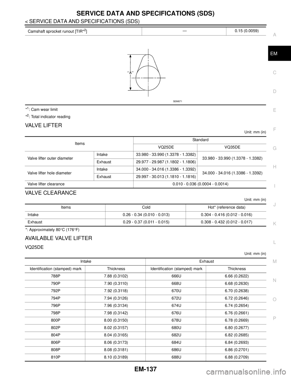
VA LV E L I F T E R
Unit: mm (in)
VALVE CLEARANCE
Unit: mm (in)
*: Approximately 80°C (176°F)
AVAILABLE VALVE LIFTER
VQ25DE
Unit: mm (in)
Camshaft sprocket runout [TIR*2]— 0.15 (0.0059)
SEM671
ItemsStandard
VQ25DE VQ35DE
Valve lifter outer diameterIntake 33.980 - 33.990 (1.3378 - 1.3382)
33.980 - 33.990 (1.3378 - 1.3382)
Exhaust 29.977 - 29.987 (1.1802 - 1.1806)
Valve lifter hole diameterIntake 34.000 - 34.016 (1.3386 - 1.3392)
34.000 - 34.016 (1.3386 - 1.3392)
Exhaust 29.997 - 30.013 (1.1810 - 1.1816)
Valve lifter clearance 0.010 - 0.036 (0.0004 - 0.0014)
Items Cold Hot* (reference data)
Intake 0.26 - 0.34 (0.010 - 0.013) 0.304 - 0.416 (0.012 - 0.016)
Exhaust 0.29 - 0.37 (0.011 - 0.015) 0.308 - 0.432 (0.012 - 0.017)
Intake Exhaust
Identification (stamped) mark Thickness Identification (stamped) mark Thickness
788P 7.88 (0.3102) 666U 6.66 (0.2622)
790P 7.90 (0.3110) 668U 6.68 (0.2630)
792P 7.92 (0.3118) 670U 6.70 (0.2638)
794P 7.94 (0.3126) 672U 6.72 (0.2646)
796P 7.96 (0.3134) 674U 6.74 (0.2654)
798P 7.98 (0.3142) 676U 6.76 (0.2661)
800P 8.00 (0.3150) 678U 6.78 (0.2669)
802P 8.02 (0.3157) 680U 6.80 (0.2677)
804P 8.04 (0.3165) 682U 6.82 (0.2685)
806P 8.06 (0.3173) 684U 6.84 (0.2693)
808P 8.08 (0.3181) 686U 6.86 (0.2701)
810P 8.10 (0.3189) 688U 6.88 (0.2709)
Page 2021 of 5121

EM-146
< SERVICE DATA AND SPECIFICATIONS (SDS)
SERVICE DATA AND SPECIFICATIONS (SDS)
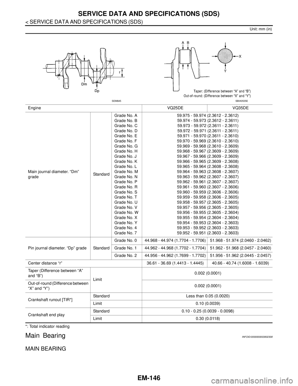
Unit: mm (in)
*: Total indicator reading
Main BearingINFOID:0000000003802308
MAIN BEARING
Engine VQ25DE VQ35DE
Main journal diameter. “Dm”
gradeStandardGrade No. A
Grade No. B
Grade No. C
Grade No. D
Grade No. E
Grade No. F
Grade No. G
Grade No. H
Grade No. J
Grade No. K
Grade No. L
Grade No. M
Grade No. N
Grade No. P
Grade No. R
Grade No. S
Grade No. T
Grade No. U
Grade No. V
Grade No. W
Grade No. X
Grade No. Y
Grade No. 4
Grade No. 759.975 - 59.974 (2.3612 - 2.3612)
59.974 - 59.973 (2.3612 - 2.3611)
59.973 - 59.972 (2.3611 - 2.3611)
59.972 - 59.971 (2.3611 - 2.3611)
59.971 - 59.970 (2.3611 - 2.3610)
59.970 - 59.969 (2.3610 - 2.3610)
59.969 - 59.968 (2.3610 - 2.3609)
59.968 - 59.967 (2.3609 - 2.3609)
59.967 - 59.966 (2.3609 - 2.3609)
59.966 - 59.965 (2.3609 - 2.3608)
59.965 - 59.964 (2.3608 - 2.3608)
59.964 - 59.963 (2.3608 - 2.3607)
59.963 - 59.962 (2.3607 - 2.3607)
59.962 - 59.961 (2.3607 - 2.3607)
59.961 - 59.960 (2.3607 - 2.3606)
59.960 - 59.959 (2.3606 - 2.3606)
59.959 - 59.958 (2.3606 - 2.3605)
59.958 - 59.957 (2.3605 - 2.3605)
59.957 - 59.956 (2.3605 - 2.3605)
59.956 - 59.955 (2.3605 - 2.3604)
59.955 - 59.954 (2.3604 - 2.3604)
59.954 - 59.953 (2.3604 - 2.3603)
59.953 - 59.952 (2.3603 - 2.3603)
59.952 - 59.951 (2.3603 - 2.3603)
Pin journal diameter. “Dp” grade StandardGrade No. 0 44.968 - 44.974 (1.7704 - 1.7706) 51.968 - 51.974 (2.0460 - 2.0462)
Grade No. 1 44.962 - 44.968 (1.7702 - 1.7704) 51.962 - 51.968 (2.0457 - 2.0460)
Grade No. 2 44.956 - 44.962 (1.7699 - 1.7702) 51.956 - 51.962 (2.0445 - 2.0457)
Center distance “r” 36.61 - 36.69 (1.4413 - 1.4445) 40.66 - 40.74 (1.6008 - 1.6039)
Taper (Difference between “A”
and “B”)
Limit0.002 (0.0001)
Out-of-round (Difference between
“X” and “Y”)0.002 (0.0001)
Crankshaft runout [TIR*]Standard Less than 0.05 (0.0020)
Limit 0.10 (0.0039)
Crankshaft end playStandard 0.10 - 0.25 (0.0039 - 0.0098)
Limit 0.30 (0.0118)
SEM645SBIA0535E