instrument panel NISSAN TEANA 2008 Service Manual
[x] Cancel search | Manufacturer: NISSAN, Model Year: 2008, Model line: TEANA, Model: NISSAN TEANA 2008Pages: 5121, PDF Size: 69.03 MB
Page 1 of 5121
MODEL J32 SERIES
© 2008 NISSAN INTERNATIONAL SA
Allrightsreserved.NopartofthisElectronicServiceManualmaybereproducedorstoredinaretrievalsystem,ortransmittedinanyform,or by any means, electronic, mechanical, photocopying, recording or otherwise, without the prior written permission of Nissan InternationalSA, Switzerland.
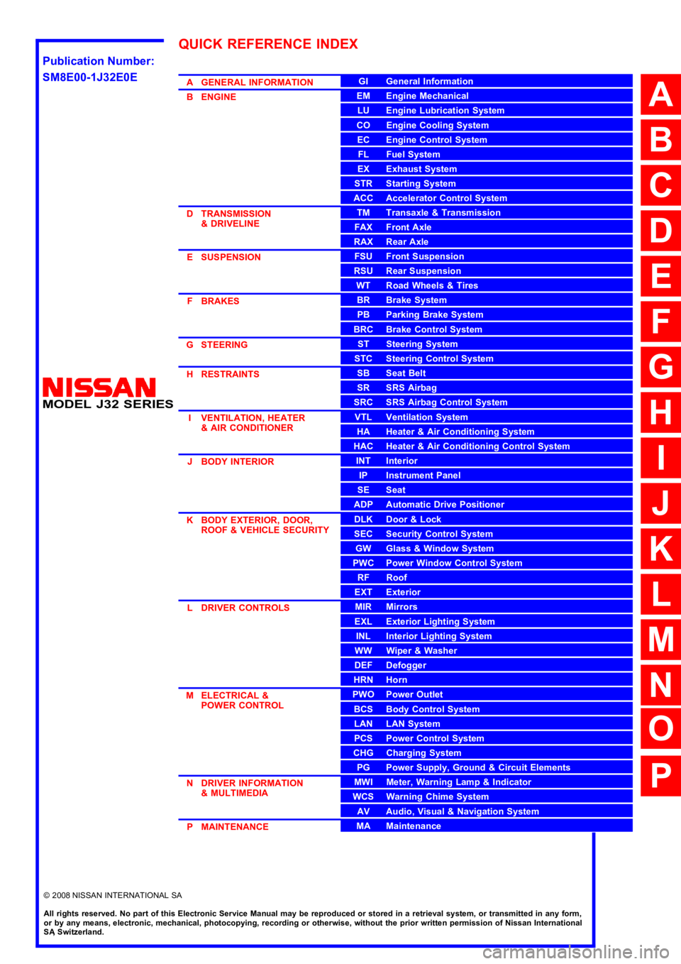
AGENERALINFORMATION
BENGINE
DTRANSMISSION&DRIVELINE
ESUSPENSION
FBRAKES
GSTEERING
HRESTRAINTS
IVENTILATION,HEATER&AIRCONDITIONER
JBODYINTERIOR
KBODYEXTERIOR,DOOR,ROOF&VEHICLESECURITY
LDRIVERCONTROLS
MELECTRICAL&POWERCONTROL
NDRIVERINFORMATION&MULTIMEDIA
PMAINTENANCE
GIGeneralInformation
EMEngineMechanical
LUEngineLubricationSystem
COEngineCoolingSystem
ECEngineControlSystem
FLFuelSystem
EXExhaustSystem
STRStartingSystem
ACCAcceleratorControlSystem
TMTransaxle &Transmission
FAXFrontAxle
RAXRearAxle
FSUFrontSuspension
RSURearSuspension
WTRoadWheels &Tires
BRBrakeSystem
PBParkingBrakeSystem
BRCBrakeControlSystem
STSteeringSystem
STCSteeringControlSystem
SBSeatBelt
SRSRSAirbag
SRCSRSAirbagControlSystem
VTLVentilationSystem
HAHeater &AirConditioningSystem
HACHeater &AirConditioningControlSystem
INTInterior
IPInstrumentPanel
SESeat
ADPAutomaticDrivePositioner
DLKDoor &Lock
SECSecurityControlSystem
GWGlass &WindowSystem
PWCPowerWindowControlSystem
RFRoof
EXTExterior
MIRMirrors
EXLExteriorLightingSystem
INLInteriorLightingSystem
WWWiper &Washer
DEFDefogger
HRNHorn
PWOPowerOutlet
BCSBodyControlSystem
LANLANSystem
PCSPowerControlSystem
CHGChargingSystem
PGPowerSupply,Ground&CircuitElements
MWIMeter,WarningLamp&Indicator
WCSWarningChimeSystem
AVAudio,Visual&NavigationSystem
MAMaintenance
QUICKREFERENCEINDEX
A
B
C
D
E
F
G
H
I
J
K
L
M
N
O
P
M
Publication Number:
SM8E00-1J32E0E
Page 15 of 5121

INSPECTION AND ADJUSTMENT
ADP-9
< BASIC INSPECTION >
C
D
E
F
G
H
I
K
L
MA
B
ADP
N
O
P
MEMORY STORING : Special Repair RequirementINFOID:0000000003759065
Memory Storage Procedure
Two positions for the driver seat can be stored for memory operation by the following procedure.
1.STEP 1
Shift selector lever to the P position.
>> GO TO 2.
2.STEP 2
Turn ignition switch ON.
>> GO TO 3.
3.STEP 3
Adjust driver seat position manually.
>> GO TO 4.
4.STEP 4
1. Push set switch.
NOTE:
Memory indicator for which driver seat position is already retained in memory is illuminated for 5 sec-
onds.
Memory indicator for which driver seat position is not retained in memory is illuminated for 0.5 seconds.
2. Push the memory switch (1 or 2) for at least 1 second within 5 seconds after pushing the set switch.
NOTE:
When entering driver seat positions into blank memory, memory indicator turns ON for 5 seconds.
When changing driver seat positions, memory indicator turns OFF for 0.5 seconds, then turns ON for 5
seconds.
NOTE:
If memory is stored in the same memory switch, the previous memory will be deleted.
Do you need to link Intelligent Keys?
YES >> GO TO 5.
NO >> END
5.STEP 6
Push the Intelligent Key unlock button within 5 seconds after pushing memory switch (while the memory indi-
cator is ON).
>> GO TO 6.
6.STEP 7
Confirm the operation of each part with memory operation and Intelligent Key interlock operation.
>> END
SYSTEM SETTING
SYSTEM SETTING : DescriptionINFOID:0000000003759066
The settings of the automatic driving positioner system can be changed, using CONSULT-III, the display unit
in the center of the instrument panel and the set switch. Always check the settings before and after discon-
necting the battery terminal or replacing driver seat control unit.
Setting Change
Page 95 of 5121
BCM (BODY CONTROL MODULE)
ADP-89
< COMPONENT DIAGNOSIS >
C
D
E
F
G
H
I
K
L
MA
B
ADP
N
O
P
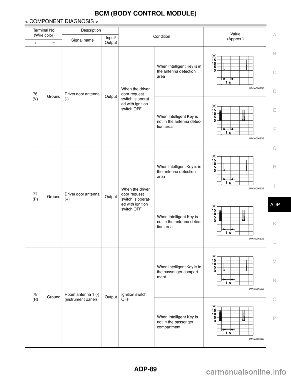
76
(V)GroundDriver door antenna
(-)OutputWhen the driver
door request
switch is operat-
ed with ignition
switch OFFWhen Intelligent Key is in
the antenna detection
area
When Intelligent Key is
not in the antenna detec-
tion area
77
(P)GroundDriver door antenna
(+)OutputWhen the driver
door request
switch is operat-
ed with ignition
switch OFFWhen Intelligent Key is in
the antenna detection
area
When Intelligent Key is
not in the antenna detec-
tion area
78
(R)GroundRoom antenna 1 (-)
(instrument panel)OutputIgnition switch
OFFWhen Intelligent Key is in
the passenger compart-
ment
When Intelligent Key is
not in the passenger
compartment Te r m i n a l N o .
(Wire color)Description
ConditionVa l u e
(Approx.)
Signal nameInput/
Output +–
JMKIA0062GB
JMKIA0063GB
JMKIA0062GB
JMKIA0063GB
JMKIA0062GB
JMKIA0063GB
Page 96 of 5121
ADP-90
< COMPONENT DIAGNOSIS >
BCM (BODY CONTROL MODULE)
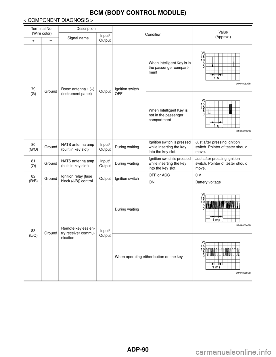
79
(G)GroundRoom antenna 1 (+)
(instrument panel)OutputIgnition switch
OFFWhen Intelligent Key is in
the passenger compart-
ment
When Intelligent Key is
not in the passenger
compartment
80
(G/O)GroundNATS antenna amp
(built in key slot)Input/
OutputDuring waitingIgnition switch is pressed
while inserting the key
into the key slot.Just after pressing ignition
switch. Pointer of tester should
move.
81
(O)GroundNATS antenna amp
(built in key slot)Input/
OutputDuring waitingIgnition switch is pressed
while inserting the key
into the key slot.Just after pressing ignition
switch. Pointer of tester should
move.
82
(R/B)GroundIgnition relay [fuse
block (J/B)] controlOutput Ignition switchOFF or ACC 0 V
ON Battery voltage
83
(L/O)GroundRemote keyless en-
try receiver commu-
nicationInput/
OutputDuring waiting
When operating either button on the key Te r m i n a l N o .
(Wire color)Description
ConditionVa l u e
(Approx.)
Signal nameInput/
Output +–
JMKIA0062GB
JMKIA0063GB
JMKIA0064GB
JMKIA0065GB
Page 870 of 5121
BCS
BCM (BODY CONTROL MODULE)
BCS-53
< ECU DIAGNOSIS >
C
D
E
F
G
H
I
J
K
L B A
O
P N
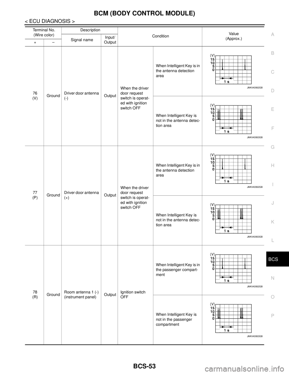
76
(V)GroundDriver door antenna
(-)OutputWhen the driver
door request
switch is operat-
ed with ignition
switch OFFWhen Intelligent Key is in
the antenna detection
area
When Intelligent Key is
not in the antenna detec-
tion area
77
(P)GroundDriver door antenna
(+)OutputWhen the driver
door request
switch is operat-
ed with ignition
switch OFFWhen Intelligent Key is in
the antenna detection
area
When Intelligent Key is
not in the antenna detec-
tion area
78
(R)GroundRoom antenna 1 (-)
(instrument panel)OutputIgnition switch
OFFWhen Intelligent Key is in
the passenger compart-
ment
When Intelligent Key is
not in the passenger
compartment Te r m i n a l N o .
(Wire color)Description
ConditionVa l u e
(Approx.)
Signal nameInput/
Output +–
JMKIA0062GB
JMKIA0063GB
JMKIA0062GB
JMKIA0063GB
JMKIA0062GB
JMKIA0063GB
Page 871 of 5121
BCS-54
< ECU DIAGNOSIS >
BCM (BODY CONTROL MODULE)
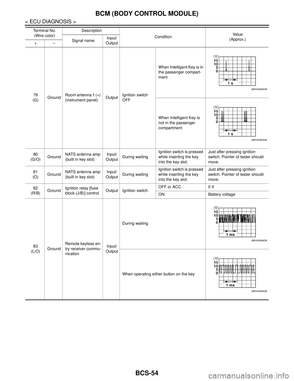
79
(G)GroundRoom antenna 1 (+)
(instrument panel)OutputIgnition switch
OFFWhen Intelligent Key is in
the passenger compart-
ment
When Intelligent Key is
not in the passenger
compartment
80
(G/O)GroundNATS antenna amp
(built in key slot)Input/
OutputDuring waitingIgnition switch is pressed
while inserting the key
into the key slot.Just after pressing ignition
switch. Pointer of tester should
move.
81
(O)GroundNATS antenna amp
(built in key slot)Input/
OutputDuring waitingIgnition switch is pressed
while inserting the key
into the key slot.Just after pressing ignition
switch. Pointer of tester should
move.
82
(R/B)GroundIgnition relay [fuse
block (J/B)] controlOutput Ignition switchOFF or ACC 0 V
ON Battery voltage
83
(L/O)GroundRemote keyless en-
try receiver commu-
nicationInput/
OutputDuring waiting
When operating either button on the key Te r m i n a l N o .
(Wire color)Description
ConditionVa l u e
(Approx.)
Signal nameInput/
Output +–
JMKIA0062GB
JMKIA0063GB
JMKIA0064GB
JMKIA0065GB
Page 903 of 5121
BRAKE PEDAL
BR-7
< ON-VEHICLE MAINTENANCE >
C
D
E
G
H
I
J
K
L
MA
B
BR
N
O
P
ADJUSTMENT
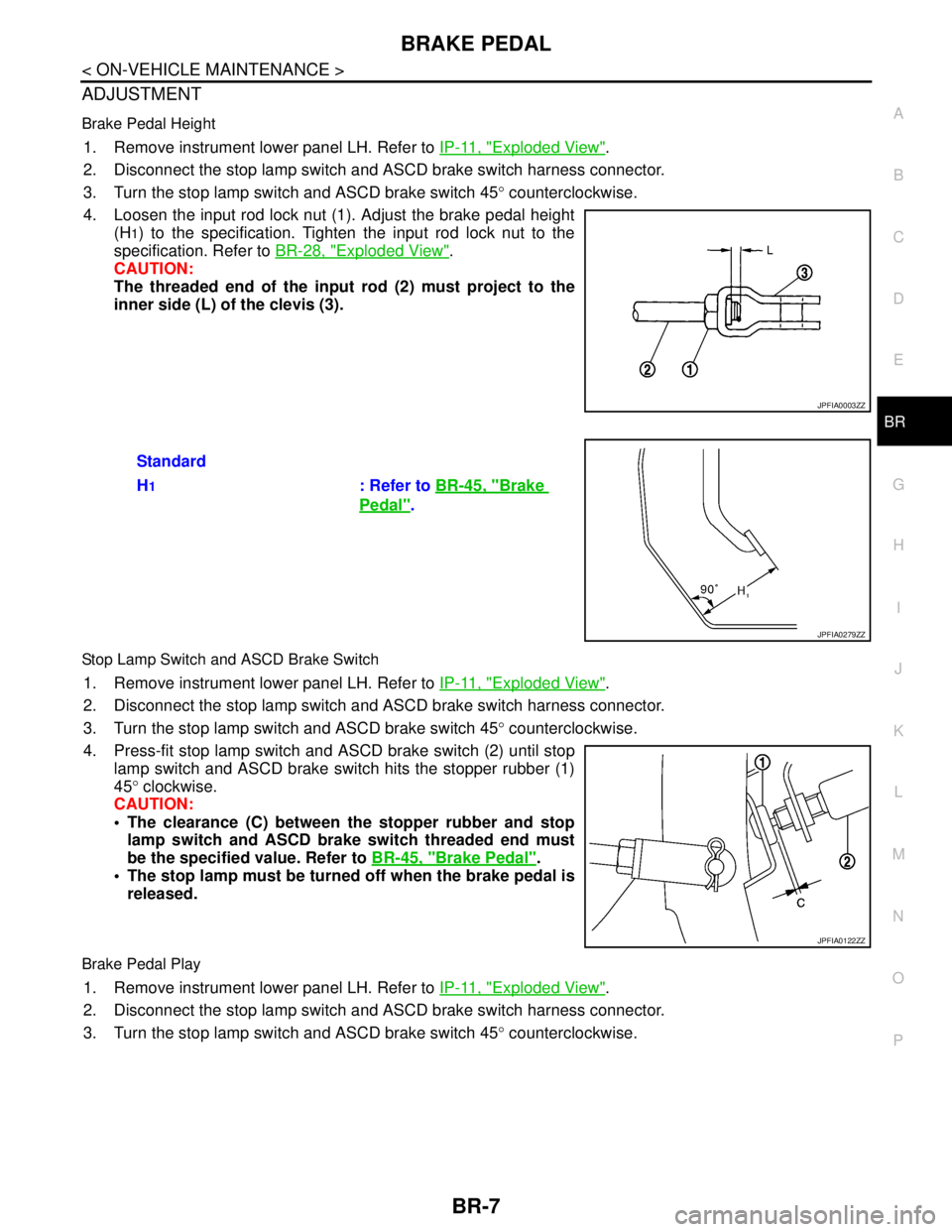
Brake Pedal Height
1. Remove instrument lower panel LH. Refer to IP-11, "Exploded View".
2. Disconnect the stop lamp switch and ASCD brake switch harness connector.
3. Turn the stop lamp switch and ASCD brake switch 45° counterclockwise.
4. Loosen the input rod lock nut (1). Adjust the brake pedal height
(H
1) to the specification. Tighten the input rod lock nut to the
specification. Refer to BR-28, "
Exploded View".
CAUTION:
The threaded end of the input rod (2) must project to the
inner side (L) of the clevis (3).
Stop Lamp Switch and ASCD Brake Switch
1. Remove instrument lower panel LH. Refer to IP-11, "Exploded View".
2. Disconnect the stop lamp switch and ASCD brake switch harness connector.
3. Turn the stop lamp switch and ASCD brake switch 45° counterclockwise.
4. Press-fit stop lamp switch and ASCD brake switch (2) until stop
lamp switch and ASCD brake switch hits the stopper rubber (1)
45° clockwise.
CAUTION:
The clearance (C) between the stopper rubber and stop
lamp switch and ASCD brake switch threaded end must
be the specified value. Refer to BR-45, "
Brake Pedal".
The stop lamp must be turned off when the brake pedal is
released.
Brake Pedal Play
1. Remove instrument lower panel LH. Refer to IP-11, "Exploded View".
2. Disconnect the stop lamp switch and ASCD brake switch harness connector.
3. Turn the stop lamp switch and ASCD brake switch 45° counterclockwise.
JPFIA0003ZZ
Standard
H
1: Refer to BR-45, "Brake
Pedal".
JPFIA0279ZZ
JPFIA0122ZZ
Page 913 of 5121
BRAKE PEDAL
BR-17
< ON-VEHICLE REPAIR >
C
D
E
G
H
I
J
K
L
MA
B
BR
N
O
P
ON-VEHICLE REPAIR
BRAKE PEDAL
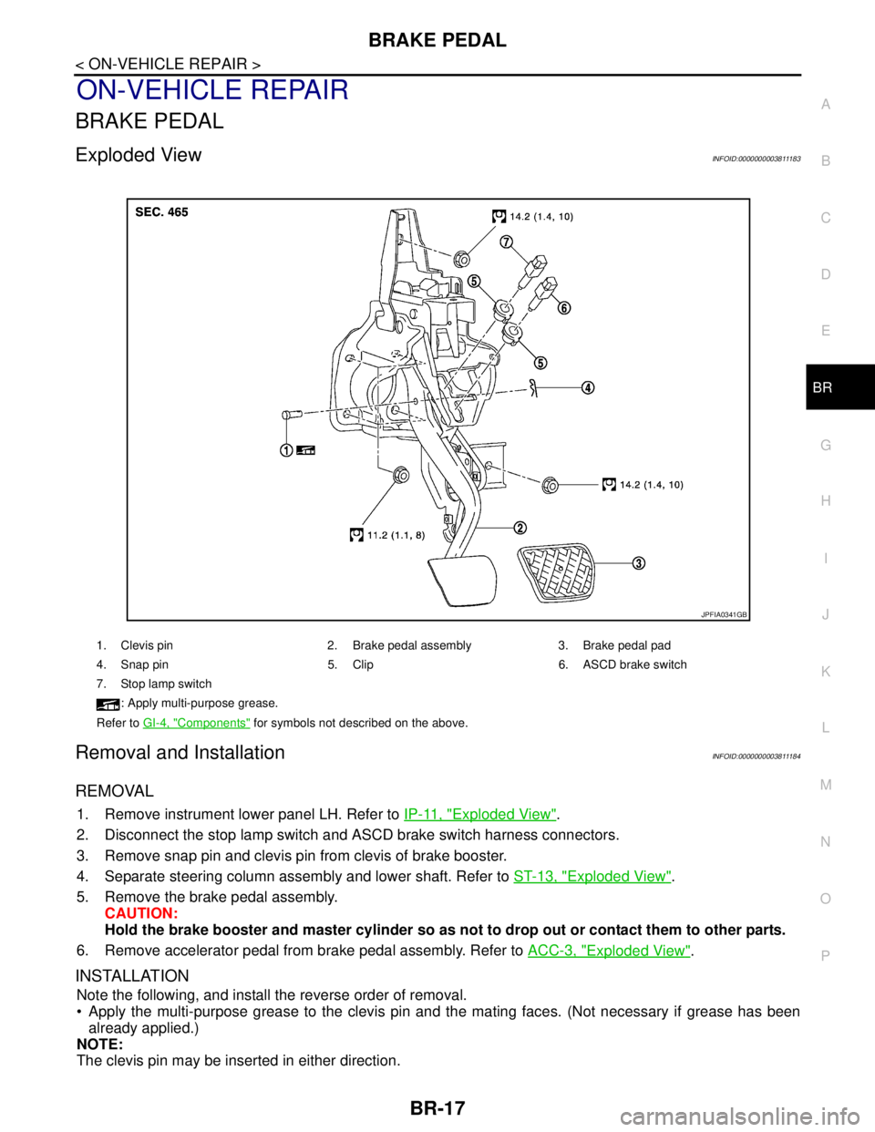
Exploded ViewINFOID:0000000003811183
Removal and InstallationINFOID:0000000003811184
REMOVAL
1. Remove instrument lower panel LH. Refer to IP-11, "Exploded View".
2. Disconnect the stop lamp switch and ASCD brake switch harness connectors.
3. Remove snap pin and clevis pin from clevis of brake booster.
4. Separate steering column assembly and lower shaft. Refer to ST-13, "
Exploded View".
5. Remove the brake pedal assembly.
CAUTION:
Hold the brake booster and master cylinder so as not to drop out or contact them to other parts.
6. Remove accelerator pedal from brake pedal assembly. Refer to ACC-3, "
Exploded View".
INSTALLATION
Note the following, and install the reverse order of removal.
Apply the multi-purpose grease to the clevis pin and the mating faces. (Not necessary if grease has been
already applied.)
NOTE:
The clevis pin may be inserted in either direction.
1. Clevis pin 2. Brake pedal assembly 3. Brake pedal pad
4. Snap pin 5. Clip 6. ASCD brake switch
7. Stop lamp switch
: Apply multi-purpose grease.
Refer to GI-4, "
Components" for symbols not described on the above.
JPFIA0341GB
Page 1011 of 5121
![NISSAN TEANA 2008 Service Manual BRC-70
< FUNCTION DIAGNOSIS >[VDC/TCS/ABS]
VDC
Component Description
INFOID:0000000003766888
A. Back of spiral cable assembly B. Combination meter C. Under center console
D. Engine room right side E. NISSAN TEANA 2008 Service Manual BRC-70
< FUNCTION DIAGNOSIS >[VDC/TCS/ABS]
VDC
Component Description
INFOID:0000000003766888
A. Back of spiral cable assembly B. Combination meter C. Under center console
D. Engine room right side E.](/img/5/57391/w960_57391-1010.png)
BRC-70
< FUNCTION DIAGNOSIS >[VDC/TCS/ABS]
VDC
Component Description
INFOID:0000000003766888
A. Back of spiral cable assembly B. Combination meter C. Under center console
D. Engine room right side E. Steering knuckle F. Instrument driver lower panel
G. Rear axle
Component parts Reference
ABS actuator and electric unit (control unit)Pump
BRC-94, "
Description"Motor
Actuator relay (main relay)BRC-106, "
Description"
Solenoid valveBRC-101, "Description"
Pressure sensorBRC-108, "Description"
VDC switch-over valve (USV1, USV2)BRC-118, "Description"
VDC switch-over valve (HSV1, HSV2)BRC-120, "Description"
Wheel sensorBRC-85, "Description"
Yaw rate/side G sensorBRC-113, "Description"
Steering angle sensorBRC-110, "Description"
VDC OFF switchBRC-126, "Description"
ABS warning lampBRC-128, "Description"
Brake warning lampBRC-129, "Description"
VDC OFF indicator lampBRC-130, "Description"
SLIP indicator lampBRC-131, "Description"
Page 1014 of 5121
![NISSAN TEANA 2008 Service Manual TCS
BRC-73
< FUNCTION DIAGNOSIS >[VDC/TCS/ABS]
C
D
E
G
H
I
J
K
L
MA
B
BRC
N
O
P
Component DescriptionINFOID:0000000003767314
A. Back of spiral cable assembly B. Combination meter C. Under center conso NISSAN TEANA 2008 Service Manual TCS
BRC-73
< FUNCTION DIAGNOSIS >[VDC/TCS/ABS]
C
D
E
G
H
I
J
K
L
MA
B
BRC
N
O
P
Component DescriptionINFOID:0000000003767314
A. Back of spiral cable assembly B. Combination meter C. Under center conso](/img/5/57391/w960_57391-1013.png)
TCS
BRC-73
< FUNCTION DIAGNOSIS >[VDC/TCS/ABS]
C
D
E
G
H
I
J
K
L
MA
B
BRC
N
O
P
Component DescriptionINFOID:0000000003767314
A. Back of spiral cable assembly B. Combination meter C. Under center console
D. Engine room right side E. Steering knuckle F. Instrument driver lower panel
G. Rear axle
Component parts Reference
ABS actuator and electric unit (control unit)Pump
BRC-94, "
Description"Motor
Actuator relay (main relay)BRC-106, "
Description"
Solenoid valveBRC-103, "Description"
Pressure sensorBRC-108, "Description"
VDC switch-over valve (USV1, USV2)BRC-118, "Description"
VDC switch-over valve (HSV1, HSV2)BRC-120, "Description"
Wheel sensorBRC-96, "Description"
Yaw rate/side G sensorBRC-113, "Description"
Steering angle sensorBRC-110, "Description"
VDC OFF switchBRC-126, "Description"
ABS warning lampBRC-128, "Description"
Brake warning lampBRC-129, "Description"
VDC OFF indicator lampBRC-130, "Description"
SLIP indicator lampBRC-131, "Description"