sensor NISSAN TEANA 2014 Service Manual
[x] Cancel search | Manufacturer: NISSAN, Model Year: 2014, Model line: TEANA, Model: NISSAN TEANA 2014Pages: 4801, PDF Size: 51.2 MB
Page 3985 of 4801
SIDE AIR BAG (SATELLITE) SENSOR
SR-23
< REMOVAL AND INSTALLATION >
C
D E
F
G
I
J
K L
M A
B
SR
N
O P
SIDE AIR BAG (S ATELLITE) SENSOR
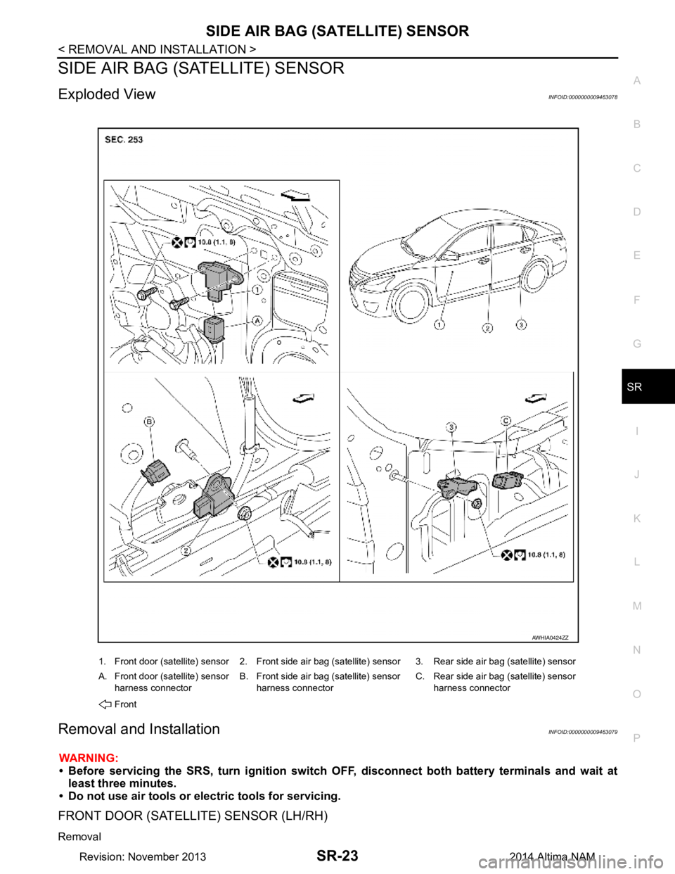
Exploded ViewINFOID:0000000009463078
Removal and InstallationINFOID:0000000009463079
WARNING:
• Before servicing the SRS, turn ignition switch OFF, disconnect both battery terminals and wait at
least three minutes.
• Do not use air tools or electric tools for servicing.
FRONT DOOR (SATELLITE) SENSOR (LH/RH)
Removal
1. Front door (satellite) sensor 2. Front side air bag (satellite) sensor 3. Rear side air bag (satellite) sensor
A. Front door (satellite) sensor harness connector B. Front side air bag (satellite) sensor
harness connector C. Rear side air bag (satellite) sensor
harness connector
Front
AWHIA0424ZZ
Revision: November 20132014 Altima NAM
Page 3986 of 4801
SR-24
< REMOVAL AND INSTALLATION >
SIDE AIR BAG (SATELLITE) SENSOR
1. Disconnect both the negative and positive battery terminals, then wait at least three minutes. Refer to PG-
73, "Removal and Installation (Battery)".
2. Remove front door finisher. Refer to INT-15, "Removal and Installation"
.
3. Disconnect the harness connector from the front door (satellite) sensor.
4. Remove the bolts and the front door (satellite) sensor. CAUTION:
• Do not reuse the front door satellite sensor bolts.
• Replace the front door satellite sensor if it has been dropped or sustained an impact.
• Do not strike the front door satellite sensor.
Installation
Installation is in the reverse order of removal.
CAUTION:
• Do not reuse the front door (satellite) sensor bolts.
• Do not damage the harness connector or harness.
• After installation is complete, check that no syst em malfunction is detected causing the air bag
warning lamp to illuminate.
• If a malfunction is indicated by the air bag warnin g lamp after repair or replacement of the malfunc-
tioning parts, perform the SRS final check. Refer to SRC-17, "SRS Final Check"
.
FRONT SIDE AIR BAG (SATELLITE) SENSOR (LH/RH)
Removal
1. Disconnect both the negative and positive battery terminal s, then wait at least three minutes. Refer to PG-
73, "Removal and Installation (Battery)".
2. Remove the front seat belt retractor. Refer to SB-8, "Removal and Installation"
.
3. Disconnect the harness connector from the front side air bag (satellite) sensor.
4. Remove the nut and the front side air bag (satellite) sensor. CAUTION:
• Do not reuse the front side air bag (satellite) sensor nut.
• Replace the front side air bag (satellite) sensor if it has been dropped or sustained an impact.
• Do not strike the front side air bag (satellite) sensor.
Installation
Installation is in the reverse order of removal.
CAUTION:
• Do not reuse the front side air bag (satellite) sensor nut.
• Do not damage the harness connector or harness.
• After installation is complete, check that no syst em malfunction is detected causing the air bag
warning lamp to illuminate.
• If a malfunction is indicated by the air bag warnin g lamp after repair or replacement of the malfunc-
tioning parts, perform the SRS final check. Refer to SRC-17, "SRS Final Check"
.
REAR SIDE AIR BAG (SATELLITE) SENSOR (LH/RH)
Removal
1. Disconnect both the negative and positive battery terminal s, then wait at least three minutes. Refer to PG-
73, "Removal and Installation (Battery)".
2. Remove the rear kicking plate inner. Refer to INT-22, "REAR KICKING PLATE : Removal and Installation
- Inner".
3. Disconnect the harness connector from the rear side air bag (satellite) sensor.
4. Remove the nut and the rear side air bag (satellite) sensor. CAUTION:
• Do not reuse the rear side air bag (satellite) sensor nut.
• Replace the rear side air bag (satellite) sensor if it has been dropped or sustained an impact.
• Do not strike the rear side air bag (satellite) sensor.
Installation
Installation is in the reverse order of removal.
CAUTION:
• Do not reuse the rear side air bag (satellite) sensor nut.
Revision: November 20132014 Altima NAM
Page 3987 of 4801

SIDE AIR BAG (SATELLITE) SENSOR
SR-25
< REMOVAL AND INSTALLATION >
C
D E
F
G
I
J
K L
M A
B
SR
N
O P
• Do not damage the harness connector or harness.
• After installation is complete, check that no syst em malfunction is detected causing the air bag
warning lamp to illuminate.
• If a malfunction is indicated by the air bag warnin g lamp after repair or replacement of the malfunc-
tioning parts, perform the SRS final check. Refer to SRC-17, "SRS Final Check"
.
Revision: November 20132014 Altima NAM
Page 3988 of 4801
SR-26
< REMOVAL AND INSTALLATION >
DIAGNOSIS SENSOR UNIT
DIAGNOSIS SENSOR UNIT
Removal and InstallationINFOID:0000000009463080
REMOVAL
WARNING:
• Before servicing the SRS, turn ig nition switch OFF, disconnect both battery terminals and wait at
least three minutes.
• Before disconnecting the air bag diagnosis sensor unit harness conn ectors, be sure to disconnect
each harness connector of the front shoulder belt pre-tensioners to prevent accidental air bag
deployment by static electricity and seat belt pre-tensioner operation.
• Do not use the air tools or electric tools for servicing.
• When replacing the air bag diagno sis sensor unit, always check with th e parts department for the lat-
est parts information. Installing an incorrect air bag diagnosis sen sor unit may or may not cause the
air bag warning lamp to illuminate and may cause in correct deployment of the supplemental air bags
and seat belt pre-tensioners in a collision r esulting in serious personal injury or death.
1. Always check the air bag diagnosis sensor unit ECU discriminated number (identification number) or part
number using CONSULT.
2. Disconnect both the negative and positive battery terminal s, then wait at least three minutes. Refer to PG-
73, "Removal and Installation (Battery)".
3. Disconnect the harness connector fo r the following SRS components: SB-8, "Removal and Installation"
(Front shoulder belt pre-tensioner LH/RH).
4. Remove the center console. Refer to IP-18, "Removal and Installation"
.
5. Disconnect the harness connector from air bag diagnosis sensor unit.
6. Remove the air bag diagnosis sensor unit bolts , then remove the air bag diagnosis sensor unit.
CAUTION:
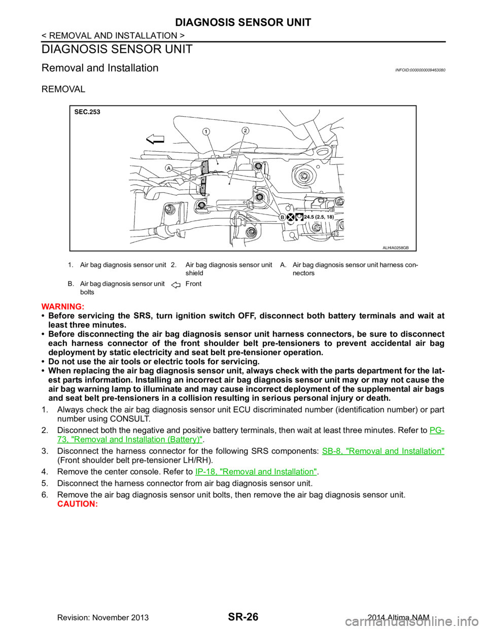
1. Air bag diagnosis sensor unit 2. Air bag diagnosis sensor unit
shieldA. Air bag diagnosis sensor unit harness con-
nectors
B. Air bag diagnosis sensor unit bolts Front
ALHIA0258GB
Revision: November 20132014 Altima NAM
Page 3989 of 4801
DIAGNOSIS SENSOR UNITSR-27
< REMOVAL AND INSTALLATION >
C
D E
F
G
I
J
K L
M A
B
SR
N
O P
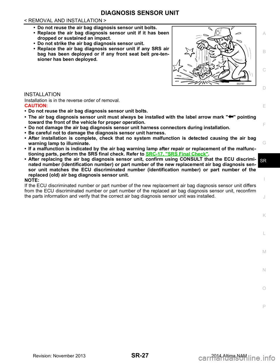
• Do not reuse the air bag di agnosis sensor unit bolts.
• Replace the air bag diagnosis sensor unit if it has been
dropped or sustained an impact.
• Do not strike the air ba g diagnosis sensor unit.
• Replace the air bag diagnosis sensor unit if any SRS air
bag has been deployed or if any front seat belt pre-ten-
sioner has been deployed.
INSTALLATION
Installation is in the reverse order of removal.
CAUTION:
• Do not reuse the air bag diagnosis sensor unit bolts.
• The air bag diagnosis sensor unit must always be installed with the label arrow mark " " pointing
toward the front of the vehicle for proper operation.
• Do not damage the air bag diagnosis sensor unit harness connectors during installation.
• Be careful not to damage the diagnosis sensor unit harness.
• After installation is complete, check that no syst em malfunction is detected causing the air bag
warning lamp to illuminate.
• If a malfunction is indicated by the air bag warnin g lamp after repair or replacement of the malfunc-
tioning parts, perform the SRS final check. Refer to SRC-17, "SRS Final Check"
.
• After replacing the air bag diagnosis sensor un it, confirm using CONSULT that the ECU discrimi-
nated number (identification number) or part nu mber of the new replacement air bag diagnosis sen-
sor unit matches the ECU discrimin ated number (identification number) or part number of the
replaced (old) air bag diagnosis sensor unit.
NOTE:
If the ECU discriminated number or pa rt number of the new replacement air bag diagnosis sensor unit differs
from the ECU discriminated number or part number of the replaced air bag diagnosis sensor unit, reconfirm
the parts information and verify that the corre ct air bag diagnosis sensor unit was installed.
SGI787
Revision: November 20132014 Altima NAM
Page 3990 of 4801
SR-28
< REMOVAL AND INSTALLATION >
OCCUPANT CLASSIFICATION SYSTEM
OCCUPANT CLASSIFICATION SYSTEM
Removal and InstallationINFOID:0000000009463081
OCCUPANT CLASSIFICATION SYSTEM CONTROL UNIT
WARNING:
• Before servicing the SRS, turn ig nition switch OFF, disconnect both battery terminals and wait at
least three minutes.
• Do not use air tools or el ectric tools for servicing.
Removal
1. Remove front passenger seat assembly. Refer to SE-30, "PASSENGER SIDE : Removal and Installation
- Seat Assembly".
2. Disconnect the harness connector from the oc cupant classification system control unit.
3. Remove occupant classification system control unit bolts.
4. Remove occupant classification system control unit. CAUTION:
• Replace the occupant classification control unit if it has been dropped or sustained an impact.
• Do not strike the occupant classification control unit.
Installation
Installation is in the reverse order of removal.
CAUTION:
• Do not damage the harness connector during installation.
• After installation is complete, check that no syst em malfunction is detected causing the air bag
warning lamp to illuminate.
• If a malfunction is indicated by the air bag warnin g lamp after repair or replacement of the malfunc-
tioning parts, perform the SRS final check. Refer to SRC-17, "SRS Final Check"
.
OCCUPANT CLASSIFICATION SYSTEM SENSORS
The occupant classification system sensors are part of the front passenger seat frame assembly. For disas-
sembly and assembly of the front passenger seat frame assembly. Refer to SE-55, "PASSENGER SIDE : Dis-
assembly and Assembly".
Revision: November 20132014 Altima NAM
Page 3994 of 4801

SRC-1
RESTRAINTS
C
D E
F
G
I
J
K L
M
SECTION SRC
A
B
SRC
N
O P
CONTENTS
SRS AIRBAG CONTROL SYSTEM
PRECAUTION ................ ...............................4
PRECAUTIONS .............................................. .....4
Precaution for Supplemental Restraint System
(SRS) "AIR BAG" and "SEAT BELT PRE-TEN-
SIONER" ............................................................. ......
4
Precaution for SRS "AIR BAG" and "SEAT BELT
PRE-TENSIONER" Service ................................ ......
4
SYSTEM DESCRIPTION ..............................5
COMPONENT PARTS ................................... .....5
Component Parts Location .................................. ......5
Component Description .............................................6
Driver Air Bag Module ...............................................7
Front Passenger Air Bag Module ..............................7
Front Side Air Bag Module .................................. ......7
Side Curtain Air Bag Module .....................................7
Front Seat Belt Pre-tensioner ....................................8
Air Bag Diagnosis Sensor Unit ..................................8
Crash Zone Sensor ...................................................8
Front Side Air Bag Satellite Sensor ...........................8
Rear Side Air Bag Satellite Sensor ...........................9
Front Door Satellite Sensor .......................................9
SRS Component Connectors ....................................9
SYSTEM .............................................................11
SRS AIR BAG SYSTEM ............................................11
SRS AIR BAG SYSTEM : Sy stem Diagram ............11
SRS AIR BAG SYSTEM : System Description ... ....11
OCCUPANT CLASSIFICATION SYSTEM ............ ....11
OCCUPANT CLASSIFICATION SYSTEM : Sys-
tem Diagram ........................................................ ....
12
OCCUPANT CLASSIFICATION SYSTEM : Sys-
tem Description ................................................... ....
12
SEAT BELT WARNING LAMP SYSTEM ..................13
SEAT BELT WARNING LAMP SYSTEM : System
Diagram ............................................................... ....
13
SEAT BELT WARNING LAMP SYSTEM : System
Description ........................................................... ....
14
DIAGNOSIS SYSTEM (AIR BAG) ....................15
Diagnosis Description ..............................................15
SRS Operation Check .............................................15
Trouble Diagnosis with CONSULT ..........................16
Trouble Diagnosis without CONSULT .....................17
SRS History Check ..................................................17
SRS Final Check .....................................................17
CONSULT Function (AIR BAG) ...............................17
CONSULT Function (OCCUPANT DETECTION) ....18
ECU DIAGNOSIS INFORMATION ..............19
DIAGNOSIS SENSOR UNIT .............................19
DTC Index ........................................................... ....19
Flash Code Index ....................................................23
WIRING DIAGRAM ......................................26
SRS AIR BAG SYSTEM ...................................26
Wiring Diagram .................................................... ....26
BASIC INSPECTION ...................................40
DIAGNOSIS AND REPAIR WORK FLOW .......40
Work Flow ............................................................ ....40
INSPECTION AND ADJUSTMENT ..................42
ADDITIONAL SERVICE WHEN REPLACING
CONTROL UNIT .................................................... ....
42
ADDITIONAL SERVICE WHEN REPLACING
CONTROL UNIT : Description ............................. ....
42
ADDITIONAL SERVICE WHEN REPLACING
CONTROL UNIT : Special Repair Requirement .. ....
42
ZERO POINT RESET ............................................. ....42
ZERO POINT RESET : Description .........................42
ZERO POINT RESET : Special Repair Require-
ment ..................................................................... ....
42
Revision: November 20132014 Altima NAMRevision: November 20132014 Altima NAM
Page 3995 of 4801

SRC-2
INTERMITTENT INCIDENT ...............................43
Inspection Procedure .......................................... ...43
Trouble Diagnosis with CONSULT .........................43
DTC/CIRCUIT DIAGNOSIS ...................... ...44
B0001, B0002 DRIVER AIRBAG MODULE ... ...44
Description ........................................................... ...44
DTC Logic ...............................................................44
Diagnosis Procedure ..............................................45
B0010, B0011 PASSENGER AIRBAG MOD-
ULE ................................................................. ...
48
Description ........................................................... ...48
DTC Logic ...............................................................48
Diagnosis Procedure ..............................................49
B0020 SIDE AIRBAG MODULE LH ..................51
Description ........................................................... ...51
DTC Logic ...............................................................51
Diagnosis Procedure ..............................................52
B0028 SIDE AIRBAG MODULE RH .................54
Description ........................................................... ...54
DTC Logic ...............................................................54
Diagnosis Procedure ..............................................55
B0021 SIDE CURTAIN AIR BAG MODULE LH
...
57
Description ........................................................... ...57
DTC Logic ...............................................................57
Diagnosis Procedure ..............................................58
B0029 SIDE CURTAIN AIR BAG MODULE
RH ................................................................... ...
60
Description ........................................................... ...60
DTC Logic ...............................................................60
Diagnosis Procedure ..............................................61
B1430, B1432 SEAT BELT PRE-TENSIONER
LH .................................................................... ...
63
Description ........................................................... ...63
DTC Logic ...............................................................63
Diagnosis Procedure ..............................................64
B1431, B1433 SEAT BELT PRE-TENSIONER
RH ................................................................... ...
66
Description ........................................................... ...66
DTC Logic ...............................................................66
Diagnosis Procedure ..............................................67
B0094 CRASH ZONE SENSOR ........................69
Description ........................................................... ...69
DTC Logic ...............................................................69
Diagnosis Procedure ..............................................70
B0091 FRONT SIDE AIR BAG SATELLITE
SENSOR LH ................................................... ...
72
Description ........................................................... ...72
DTC Logic ...............................................................72
Diagnosis Procedure ..............................................73
B0096 FRONT SIDE AIR BAG SATELLITE
SENSOR RH ................................................... ...
75
Description ........................................................... ...75
DTC Logic ...............................................................75
Diagnosis Procedure ...............................................76
B0092 REAR SIDE AIR BAG SATELLITE
SENSOR LH ................................................... ...
78
Description ........................................................... ...78
DTC Logic ...............................................................78
Diagnosis Procedure ...............................................79
B0097 REAR SIDE AIR BAG SATELLITE
SENSOR RH ................................................... ...
81
Description ........................................................... ...81
DTC Logic ...............................................................81
Diagnosis Procedure ...............................................82
B0093 FRONT DOOR SATELLITE SENSOR
LH ................................................................... ...
84
Description ........................................................... ...84
DTC Logic ...............................................................84
Diagnosis Procedure ...............................................85
B0098 FRONT DOOR SATELLITE SENSOR
RH ................................................................... ...
87
Description ........................................................... ...87
DTC Logic ...............................................................87
Diagnosis Procedure ...............................................88
B14XX AIR BAG DIAGNOSIS SENSOR UNIT ...90
Description ........................................................... ...90
DTC Logic ...............................................................90
Diagnosis Procedure ...............................................91
B00D5 PASSENGER AIR BAG OFF INDICA-
TOR ................................................................. ...
93
Description ........................................................... ...93
DTC Logic ...............................................................93
Diagnosis Procedure ...............................................94
B1428 SEAT BELT BUCKLE SWITCH LH .......96
Description ........................................................... ...96
DTC Logic ...............................................................96
Diagnosis Procedure ...............................................97
B1429 SEAT BELT BUCKLE SWITCH RH ......98
Description ........................................................... ...98
DTC Logic ...............................................................98
Diagnosis Procedure ...............................................99
B00A0 OCS SYSTEM .................................... ..100
Description ........................................................... .100
DTC Logic .............................................................100
Diagnosis Procedure .............................................101
B142X COLLISION DETECTION .....................103
Description ........................................................... .103
DTC Logic .............................................................103
Diagnosis Procedure .............................................103
Revision: November 20132014 Altima NAMRevision: November 20132014 Altima NAM
Page 3997 of 4801

SRC-4
< PRECAUTION >
PRECAUTIONS
PRECAUTION
PRECAUTIONS
Precaution for Supplemental Restraint System (SRS) "AIR BAG" and "SEAT BELT
PRE-TENSIONER"
INFOID:0000000009460702
The Supplemental Restraint System such as “A IR BAG” and “SEAT BELT PRE-TENSIONER”, used along
with a front seat belt, helps to reduce the risk or severi ty of injury to the driver and front passenger for certain
types of collision. Information necessary to service the system safely is included in the SR and SB section of
this Service Manual.
WARNING:
• To avoid rendering the SRS inopera tive, which could increase the risk of personal injury or death in
the event of a collision which would result in air bag inflation, all maintenance must be performed by
an authorized NISS AN/INFINITI dealer.
• Improper maintenance, including in correct removal and installation of the SRS, can lead to personal
injury caused by unintent ional activation of the system. For re moval of Spiral Cable and Air Bag
Module, see the SR section.
• Do not use electrical test equipmen t on any circuit related to the SRS unless instructed to in this
Service Manual. SRS wiring harn esses can be identified by yellow and/or orange harnesses or har-
ness connectors.
PRECAUTIONS WHEN USING POWER TOOLS (AIR OR ELECTRIC) AND HAMMERS
WARNING:
• When working near the Airbag Diagnosis Sensor Unit or other Airbag System sensors with the Igni-
tion ON or engine running, DO NOT use air or electri c power tools or strike near the sensor(s) with a
hammer. Heavy vibration could activate the sensor( s) and deploy the air bag(s), possibly causing
serious injury.
• When using air or electric power tools or hammers , always switch the Ignition OFF, disconnect the
battery and wait at least three minutes before performing any service.
Precaution for SRS "AIR BAG" and "S EAT BELT PRE-TENSIONER" Service
INFOID:0000000009460703
• Do not use electrical test equipment to check SRS ci rcuits unless instructed to in this Service Manual.
• Before servicing the SRS, turn ignition switch OFF, disconnect both battery cables and wait at least 3 min-
utes.
For approximately 3 minutes after the cables are removed, it is still possible for the air bag and seat belt pre-
tensioner to deploy. Therefore, do not work on any SR S connectors or wires until at least 3 minutes have
passed.
• The air bag diagnosis sensor unit must always be installed with the arrow mark “ ⇐” pointing toward the front
of the vehicle for proper operation. Also check air bag diagnosis sensor unit for cracks, deformities or rust
before installation and replace as required.
• The spiral cable must be aligned with the neutral position since its rotations are limited. Do not attempt to
turn steering wheel or column after removal of steering gear.
• Handle air bag module carefully. Always place driver and front passenger air bag modules with the pad side facing upward and seat mounted front side air bag m odule standing with the stud bolt side facing down.
• Conduct self-diagnosis to check entire SRS for proper function after replacing any components.
• After air bag inflates, the front instrument panel assembly should be replaced if damaged.
Revision: November 20132014 Altima NAMRevision: November 20132014 Altima NAM
Page 3999 of 4801
SRC-6
< SYSTEM DESCRIPTION >
COMPONENT PARTS
Component Description
INFOID:0000000009460705
1. Driver air bag module 2. Front passenger air bag off indicator 3. Front passenger air bag module
4. Front LH side air bag module (RH similar) 5. LH side curtain air bag module
(view with headliner removed)
(RH similar) 6. Front LH seatbelt pre-tensioner
(view with lower cent er pillar cover LH
removed)
(RH similar)
7. Occupant classification system control unit (A)
Occupant classification system sen-
sors (B)
(view with front passenger seat re-
moved) 8. Crash zone sensor
(view with air intake removed) 9. Front door satellite sensor LH
(view with front door finisher LH re-
moved)
(RH similar)
10. Front side air bag satellite sensor LH (view with lower cent er pillar cover LH
removed)
(RH similar) 11. Rear side air bag satellite sensor LH
(view with dash side lower finisher LH
removed)
(RH similar) 12. Seat belt buckle switch (driver seat)
(passenger seat similar)
13. Spiral cable (view with steeri ng wheel removed) 14. Air bag diagnosis sensor unit
(view with center console assembly
removed)
Component Function
Air bag diagnosis sensor unit Refer to SRC-8, "Air Bag Diagnosis Sensor Unit"
.
Driver air bag module Refer to SRC-7, "Driver Air Bag Module"
.
Front passenger air bag module Refer to SRC-7, "Front Passenger Air Bag Module"
.
Front side air bag module Refer to SRC-7, "Front Side Air Bag Module"
.
Side curtain air bag module Refer to SRC-7, "Side Curtain Air Bag Module"
.
Front seat belt pre-tensioner Refer to SRC-8, "Front Seat Belt Pre-tensioner"
.
Occupant classification system Refer to
SRC-12, "OCCUPANT CLASSIFICATION SYSTEM : System Descrip-
tion".
Crash zone sensor Refer to SRC-8, "Crash Zone Sensor"
.
Front side air bag (satellite) sensor Refer to SRC-8, "Front Side Air Bag Satellite Sensor"
.
Rear side air bag (satellite) sensor Refer to SRC-9, "Rear Side Air Bag Satellite Sensor"
.
Front door (satellite) sensor Refer to SRC-9, "Front Door Satellite Sensor"
.
Seat belt buckle switch The driver seat belt buckle switch and passenger seat belt buckle switch provide
the seat belt buckle signals to the air bag diagnosis sensor unit and the combina-
tion meter.
Sp iral c ab le The spiral cable provides a rotating physical connection to the driver air bag mod-
ule.
Combination meter The combination meter displays the air bag warning lamp and the seat belt warn-
ing lamp. The air bag warning lamp is used for diagnosis in User Mode and may
be used to display diagnostic trouble codes without the use of the CONSULT.
Revision: November 20132014 Altima NAMRevision: November 20132014 Altima NAM