Heater NISSAN TEANA 2014 User Guide
[x] Cancel search | Manufacturer: NISSAN, Model Year: 2014, Model line: TEANA, Model: NISSAN TEANA 2014Pages: 4801, PDF Size: 51.2 MB
Page 431 of 4801

WATER OUTLET AND WATER PIPINGCO-51
< REMOVAL AND INSTALLATION > [VQ35DE]
C
D E
F
G H
I
J
K L
M A
CO
NP
O
WATER OUTLET AND WATER PIPING
Exploded ViewINFOID:0000000009460424
WARNING:
Do not remove the radiator cap when the engine is hot. Serious burns could occur from high-pressure
engine coolant escaping from the radiator. Wrap a thick cloth around the cap. Slowly push down and
turn it a quarter turn to allow built-up pressure to escape. Carefully remove the cap by pushing it down
and turning it all the way.
NOTE:
When removing components such as hoses, tubes/lines, etc. , cap or plug openings to prevent fluid from spill-
ing.
Removal and InstallationINFOID:0000000009460425
REMOVAL
1. Remove engine room cover. Refer to EM-28, "Removal and Installation".
CAUTION:
Perform when the engine is cold.
1. Heater hose 2. Clamp 3. Water hose
4. Clamp 5. Water outlet 6. Gasket
7. Gasket 8. Water connector 9. O-ring
10. Water bypass pipe 11. Clamp 12. Water hose
13. Heater pipe 14. Water hose 15. Heater hose
16. Engine coolant temperature sensor 17. Clamp 18. Radiator hose (upper)
A. To heater core B. To electric throttle control actuator C. To oil cooler
D. To radiator
AWBIA1107GB
Revision: November 20132014 Altima NAM
Page 432 of 4801

CO-52
< REMOVAL AND INSTALLATION >[VQ35DE]
WATER OUTLET AND WATER PIPING
2. Partially drain engine coolant from radiator. Refer to
CO-36, "Changing Engine Coolant".
3. Remove the core support cover clips (A), then remove the core support cover (1).
4. Remove front air duct. Refer to EM-84, "Removal and Installation"
.
5. Remove air duct and air cleaner case assembly. Refer to EM-144, "Removal and Installation"
.
6. Remove engine side under cover (RH). Refer to EXT-28, "Removal and Installation"
.
7. Disconnect hoses from electric throttle control actuator.
8. Remove radiator upper hose and heater hoses.
9. Remove connector(s) from heater pipe.
10. Disconnect engine coolant temperature sens or electrical connector on water outlet.
11. Remove water outlet, heater pipe, water connector, and water bypass pipe nuts and bolts.
12. Remove engine coolant temperature sensor, if necessary.
INSTALLATION
Installation is in the reverse order of removal.
• Securely insert each hose, and install a clamp at a pos ition where it does not interfere with the pipe bulge.
• When inserting heater pipe and water bypass pipe into water connector, apply mild soap to new O-rings.
CAUTION:
Do not reuse O-ring.
• After installation refill engine coolant and check for leaks. Refer to CO-36, "Changing Engine Coolant"
and
CO-35, "System Inspection"
.
ALKIA2602ZZ
Revision: November 20132014 Altima NAM
Page 1003 of 4801
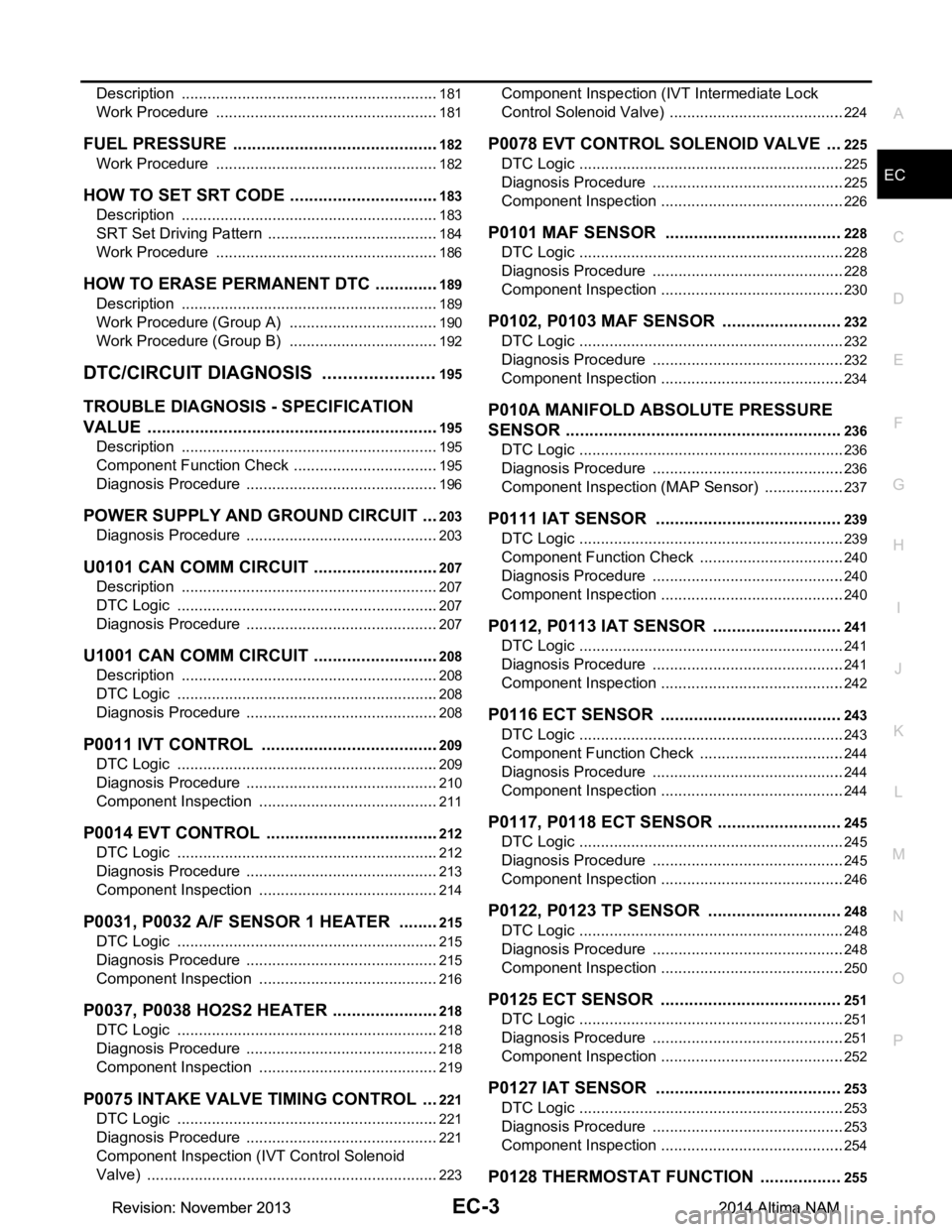
EC-3
C
D E
F
G H
I
J
K L
M
EC A
N
O P
Description ..........................................................
..
181
Work Procedure ....................................................181
FUEL PRESSURE .......................................... ..182
Work Procedure .................................................. ..182
HOW TO SET SRT CODE ................................183
Description .......................................................... ..183
SRT Set Driving Pattern ........................................184
Work Procedure ....................................................186
HOW TO ERASE PERMANENT DTC ..............189
Description .......................................................... ..189
Work Procedure (Group A) ...................................190
Work Procedure (Group B) ...................................192
DTC/CIRCUIT DIAGNOSIS .......................195
TROUBLE DIAGNOSIS - SPECIFICATION
VALUE ............................................................ ..
195
Description .......................................................... ..195
Component Function Check ..................................195
Diagnosis Procedure .............................................196
POWER SUPPLY AND GROUND CIRCUIT ....203
Diagnosis Procedure ........................................... ..203
U0101 CAN COMM CIRCUIT ...........................207
Description .......................................................... ..207
DTC Logic .............................................................207
Diagnosis Procedure .............................................207
U1001 CAN COMM CIRCUIT ...........................208
Description .......................................................... ..208
DTC Logic .............................................................208
Diagnosis Procedure .............................................208
P0011 IVT CONTROL ......................................209
DTC Logic ........................................................... ..209
Diagnosis Procedure .............................................210
Component Inspection ..........................................211
P0014 EVT CONTROL .....................................212
DTC Logic ........................................................... ..212
Diagnosis Procedure .............................................213
Component Inspection ..........................................214
P0031, P0032 A/F SENSOR 1 HEATER .........215
DTC Logic ........................................................... ..215
Diagnosis Procedure .............................................215
Component Inspection ..........................................216
P0037, P0038 HO2S2 HEATER .......................218
DTC Logic ........................................................... ..218
Diagnosis Procedure .............................................218
Component Inspection ..........................................219
P0075 INTAKE VALVE TIMING CONTROL ....221
DTC Logic ........................................................... ..221
Diagnosis Procedure .............................................221
Component Inspection (IVT Control Solenoid
Valve) .................................................................. ..
223
Component Inspection (IVT Intermediate Lock
Control Solenoid Valve) ....................................... ..
224
P0078 EVT CONTROL SOLENOID VALVE ...225
DTC Logic ..............................................................225
Diagnosis Procedure .............................................225
Component Inspection ...........................................226
P0101 MAF SENSOR .....................................228
DTC Logic ..............................................................228
Diagnosis Procedure .............................................228
Component Inspection ...........................................230
P0102, P0103 MAF SENSOR .........................232
DTC Logic ..............................................................232
Diagnosis Procedure .............................................232
Component Inspection ...........................................234
P010A MANIFOLD ABSOLUTE PRESSURE
SENSOR ..........................................................
236
DTC Logic ............................................................ ..236
Diagnosis Procedure .............................................236
Component Inspection (MAP Sensor) ...................237
P0111 IAT SENSOR .......................................239
DTC Logic ..............................................................239
Component Function Check ..................................240
Diagnosis Procedure .............................................240
Component Inspection ...........................................240
P0112, P0113 IAT SENSOR ...........................241
DTC Logic ..............................................................241
Diagnosis Procedure .............................................241
Component Inspection ...........................................242
P0116 ECT SENSOR ......................................243
DTC Logic ..............................................................243
Component Function Check ..................................244
Diagnosis Procedure .............................................244
Component Inspection ...........................................244
P0117, P0118 ECT SENSOR ..........................245
DTC Logic ..............................................................245
Diagnosis Procedure .............................................245
Component Inspection ...........................................246
P0122, P0123 TP SENSOR ............................248
DTC Logic ..............................................................248
Diagnosis Procedure .............................................248
Component Inspection ...........................................250
P0125 ECT SENSOR ......................................251
DTC Logic ..............................................................251
Diagnosis Procedure .............................................251
Component Inspection ...........................................252
P0127 IAT SENSOR .......................................253
DTC Logic ..............................................................253
Diagnosis Procedure .............................................253
Component Inspection ...........................................254
P0128 THERMOSTAT FUNCTION .................255
Revision: November 20132014 Altima NAMRevision: November 20132014 Altima NAM
Page 1010 of 4801

EC-10
POWER SUPPLY AND GROUND CIRCUIT ...709
Diagnosis Procedure ........................................... ..709
U0101 CAN COMM CIRCUIT ..........................713
Description ........................................................... ..713
DTC Logic ..............................................................713
Diagnosis Procedure .............................................713
U1001 CAN COMM CIRCUIT ..........................714
Description ........................................................... ..714
DTC Logic ..............................................................714
Diagnosis Procedure .............................................714
P0011, P0021 IVT CONTROL .........................715
DTC Logic ............................................................ ..715
Diagnosis Procedure .............................................716
Component Inspection ...........................................717
P0031, P0032, P0051, P0052 A/F SENSOR 1
HEATER .......................................................... .
719
DTC Logic ............................................................ ..719
Diagnosis Procedure .............................................719
Component Inspection ...........................................720
P0037, P0038, P0057, P0058 HO2S2 HEAT-
ER ................................................................... .
722
DTC Logic ............................................................ ..722
Diagnosis Procedure .............................................722
Component Inspection ...........................................723
P0075, P0081 IVT CONTROL SOLENOID
VALVE ............................................................ .
725
DTC Logic ............................................................ ..725
Diagnosis Procedure .............................................725
Component Inspection ...........................................726
P0101 MAF SENSOR ......................................727
DTC Logic ............................................................ ..727
Diagnosis Procedure .............................................727
Component Inspection ...........................................729
P0102, P0103 MAF SENSOR ..........................732
DTC Logic ............................................................ ..732
Diagnosis Procedure .............................................732
Component Inspection ...........................................733
P0111 IAT SENSOR ........................................736
DTC Logic ............................................................ ..736
Component Function Check ..................................737
Diagnosis Procedure .............................................737
Component Inspection ...........................................737
P0112, P0113 IAT SENSOR ............................738
DTC Logic ............................................................ ..738
Diagnosis Procedure .............................................738
Component Inspection ...........................................739
P0116 ECT SENSOR .......................................740
DTC Logic ............................................................ ..740
Component Function Check ..................................741
Diagnosis Procedure .............................................741
Component Inspection ......................................... .741
P0117, P0118 ECT SENSOR ...........................742
DTC Logic ............................................................ .742
Diagnosis Procedure .............................................742
Component Inspection ..........................................743
P0122, P0123 TP SENSOR ..............................744
DTC Logic ............................................................ .744
Diagnosis Procedure .............................................744
Component Inspection ..........................................745
P0125 ECT SENSOR .......................................746
DTC Logic ............................................................ .746
Diagnosis Procedure .............................................746
Component Inspection ..........................................747
P0127 IAT SENSOR .........................................748
DTC Logic ............................................................ .748
Diagnosis Procedure .............................................748
Component Inspection ..........................................749
P0128 THERMOSTAT FUNCTION ..................750
DTC Logic ............................................................ .750
Diagnosis Procedure .............................................751
Component Inspection ..........................................751
P0130, P0150 A/F SENSOR 1 .........................753
DTC Logic ............................................................ .753
Component Function Check .................................754
Diagnosis Procedure .............................................755
P0131, P0151 A/F SENSOR 1 .........................757
DTC Logic ............................................................ .757
Diagnosis Procedure .............................................758
P0132, P0152 A/F SENSOR 1 .........................760
DTC Logic ............................................................ .760
Diagnosis Procedure .............................................761
P0137, P0157 HO2S2 .......................................763
DTC Logic ............................................................ .763
Component Function Check .................................764
Diagnosis Procedure .............................................765
Component Inspection ..........................................766
P0138, P0158 HO2S2 .......................................768
DTC Logic ............................................................ .768
Component Function Check .................................769
Diagnosis Procedure .............................................770
Component Inspection ..........................................773
P0139, P0159 HO2S2 .......................................775
DTC Logic ............................................................ .775
Component Function Check .................................776
Diagnosis Procedure .............................................777
Component Inspection ..........................................778
P014C, P014D, P014E, P014F, P015A,
P015B, P015C, P015D A/F SENSOR 1 ......... ..
781
DTC Logic ............................................................ .781
Diagnosis Procedure .............................................783
Revision: November 20132014 Altima NAMRevision: November 20132014 Altima NAM
Page 1028 of 4801

EC-28
< SYSTEM DESCRIPTION >[QR25DE]
COMPONENT PARTS
The mass air flow sensor is placed in the stream of intake air. It
measures the intake flow rate by measuring a part of the entire
intake flow. The MAF sensor controls the temperature of the heater
in sensing element to a certain amount. The temperature distribution
around the heater changes according to the increase in intake air
volume. The change is detected by a thermistor and the air volume
data is sent to ECM by the MAF sensor.
INTAKE AIR TEMPERATURE SENSOR
The intake air temperature sensor is built-into mass air flow sensor. The sensor detects intake air temperature
and transmits a signal to the ECM.
The temperature sensing unit uses a thermistor wh ich is sensitive to the change in temperature.
*: These data are reference values on the diagnosis tool.
Manifold Absolute Pressure SensorINFOID:0000000009462062
The manifold absolute pressure (MAP) sensor is placed at intake
manifold collector. It detects intake manifold pressure and sends the
voltage signal to the ECM.
The sensor uses a silicon diaphragm which is sensitive to the
change in pressure. As the pressure increases, the voltage rises.
NOTE:
The sensor is equipped, but used for trouble diagnosis only.
Engine Coolant Te mperature SensorINFOID:0000000009462063
The engine coolant temperature sensor is used to detect the engine
coolant temperature. The sensor modifies a voltage signal from the
ECM. The modified signal returns to the ECM as the engine coolant
temperature input. The sensor uses a thermistor which is sensitive to
the change in temperature. The elec trical resistance of the ther-
mistor decreases as temperature increases.
PBIA9559J
Intake air temperature
[° C ( °F)] Vo l ta g e* (V)
25 (77) 1.9 – 2.1
80 (176) 3.2 – 3.4
JPBIA4619ZZ
JPBIA5280ZZ
Revision: November 20132014 Altima NAMRevision: November 20132014 Altima NAM
Page 1032 of 4801

EC-32
< SYSTEM DESCRIPTION >[QR25DE]
COMPONENT PARTS
Air Fuel Ratio (A/F) Sensor 1
INFOID:0000000009462072
The sensor element of the A/F sensor 1 is composed an electrode
layer, which transports ions. It has a heater in the element.
The sensor is capable of precise measurement = 1, but also in the lean and rich range. Together with its
control electronics, the sensor outputs a cl ear, continuous signal throughout a wide range.
The exhaust gas components diffuse through the diffusi on layer at the sensor cell. An electrode layer is
applied voltage, and this current relati ve oxygen density in lean. Also this current relative hydrocarbon density
in rich.
Therefore, the A/F sensor 1 is able to indicate air fuel ratio by this
electrode layer of current. In additi on, a heater is integrated in the
sensor to ensure the required operating temperature of approxi-
mately 760 °C (1,400 °F).
A/F SENSOR 1 HEATER
A/F sensor 1 heater is integrated in the sensor.
The ECM performs ON/OFF duty control of the A/F sensor 1 heater corresponding to the engine operating
condition to keep the temperature of A/F s ensor 1 element within the specified range.
Heated Oxygen Sensor 2INFOID:0000000009462073
The heated oxygen sensor 2, after three way catalyst (manifold),
monitors the oxygen level in the exhaust gas.
Even if switching characteristics of the air fuel ratio (A/F) sensor 1
are shifted, the air fuel ratio is controlled to stoichiometric, by the sig-
nal from the heated oxygen sensor 2.
This sensor is made of ceramic zirconia. The zirconia generates volt-
age from approximately 1 V in richer conditions to 0 V in leaner con-
ditions.
Under normal conditions the heated ox ygen sensor 2 is not used for
engine control operation.
HEATED OXYGEN SENSOR 2 HEATER
Heated oxygen sensor 2 heater is integrated in the sensor.
The ECM performs ON/OFF control of the heated oxy gen sensor 2 heater corresponding to the engine speed,
amount of intake air and engine coolant temperature.
JPBIA4038GB
JPBIA5446GB
SEF327R
Revision: November 20132014 Altima NAMRevision: November 20132014 Altima NAM
Page 1033 of 4801

COMPONENT PARTSEC-33
< SYSTEM DESCRIPTION > [QR25DE]
C
D E
F
G H
I
J
K L
M A
EC
NP
O
Knock SensorINFOID:0000000009462074
The knock sensor is attached to t
he cylinder block. It senses engine
knocking using a piezoelectric el ement. A knocking vibration from
the cylinder block is sensed as vibrational pressure. This pressure is
converted into a voltage signal and sent to the ECM.
Engine Oil Pressure SensorINFOID:0000000009462075
The engine oil pressure (EOP) sens or is detects engine oil pressure
and transmits a voltage signal to the ECM.
Engine Oil Temperature SensorINFOID:0000000009462076
The engine oil temperature sensor is used to detect the engine oil
temperature. The sensor modifies a voltage signal from the ECM.
The modified signal returns to the ECM as the engine oil tempera-
ture input. The sensor uses a ther mistor which is sensitive to the
change in temperature. The electrical resistance of the thermistor
decreases as temperature increases.
Engine speed Heated oxygen sensor 2 heater
Above 3,600 rpm OFF
Below 3,600 rpm after the following conditions are met.
• Engine: After warming up
• Keeping the engine speed between 3,500 and 4,000 rpm for 1
minute and at idle for 1 minute under no load ON
JSBIA0284ZZ
JSBIA0292ZZ
JPBIA5280ZZ
Revision: November 20132014 Altima NAMRevision: November 20132014 Altima NAM
Page 1080 of 4801

EC-80
< SYSTEM DESCRIPTION >[QR25DE]
DIAGNOSIS SYSTEM (ECM)
TP SEN 1-B1
V××
• The throttle position sensor signal volt-age is displayed. • TP SEN 2-B1 signal is convert-
ed by ECM internally. Thus, it
differs from ECM terminal volt-
age signal.
TP SEN 2-B1
××
FUEL T/TMP SE °C or °F • The fuel temperature (determined by the
signal voltage of the fuel tank tempera-
ture sensor) is displayed.
EVAP SYS PRES V • The signal voltage of EVAP control sys-
tem pressure sensor is displayed.
FUEL LEVEL SE V ו The signal voltage of the fuel level sensor
is displayed.
START SIGNAL On/Off • Indicates start signal status [ON/OFF]
computed by the ECM according to the
signals of engine speed and battery volt-
age. • After starting the engine, [OFF]
is displayed regardless of the
starter signal.
CLSD THL POS On/Off ×ו Indicates idle position [ON/OFF] comput-
ed by ECM according to the accelerator
pedal position sensor signal.
AIR COND SIG On/Off ×ו Indicates [ON/OFF] condition of the air
conditioner switch as determined by the
air conditioner signal.
PW/ST SIGNAL On/Off ×ו [ON/OFF] condition of the power steering
system (determined by the signal sent
from EPS control unit) is indicated.
LOAD SIGNAL On/Off ×ו Indicates [ON/OFF] condition from the
electrical load signal.
- On: Rear window defogger switch is ON and/or lighting switch is in 2nd position.
- Off: Both rear window defogger switch
and lighting switch are OFF.
IGNITION SW On/Off ×ו Indicates [ON/OFF] condition from igni-
tion switch signal.
HEATER FAN SW On/Off ו Indicates [ON/OFF] condition from the
heater fan switch signal.
BRAKE SW On/Off • Indicates [ON/OFF] condition from the
stop lamp switch signal.
INJ PULSE-B1 msec • Indicates the actual fuel injection pulse
width compensated by ECM according to
the input signals. • When the engine is stopped, a
certain computed value is indi-
cated.
IGN TIMING BTDC ו Indicates the ignition timing computed by
ECM according to the input signals. • When the engine is stopped, a
certain value is indicated.
CAL/LD VALUE % • “Calculated load value” indicates the val-
ue of the current air flow divided by peak
air flow.
MASS AIRFLOW g/s • Indicates the mass air flow computed by
ECM according to the signal voltage of
the mass air flow sensor.
Monitored item Unit
Monitor Item
Selection
Description Remarks
ECU
IN-
PUT
SIG-
NALS MAIN
SIG-
NAL S
Revision: November 20132014 Altima NAMRevision: November 20132014 Altima NAM
Page 1081 of 4801

DIAGNOSIS SYSTEM (ECM)EC-81
< SYSTEM DESCRIPTION > [QR25DE]
C
D E
F
G H
I
J
K L
M A
EC
NP
O
PURG VOL C/V %
• Indicates the EVAP canister purge vol-
ume control solenoid valve control value
computed by the ECM according to the
input signals.
• The opening becomes larger as the val- ue increases.
INT/V TIM(B1) °CA • Indicates [
°CA] of intake camshaft ad-
vance angle.
EXH/V TIM B1 °CA • Indicates [
°CA] of exhaust camshaft ad-
vance angle.
INT/V SOL(B1) %• The control value of the intake valve tim-
ing control solenoid valve (determined by
ECM according to the input signals) is in-
dicated.
• The advance angle becomes larger as
the value increases.
SWRL CONT S/V On/Off • The control condition of the intake mani-
fold runner control valve (determined by
ECM according to the input signals) is in-
dicated.
- On: Closed
- Off: Open
VIAS S/V-1 On/Off • The control condition of the intake mani-
fold tuning valve (determined by ECM ac-
cording to the input signals) is indicated.
- On: Closed
- Off: Open
AIR COND RLY On/Off • The air conditioner relay control condi-
tion (determined by ECM according to
the input signals) is indicated.
FUEL PUMP RLY On/Off • Indicates the fuel pump relay control con-
dition determined by ECM according to
the input signals.
VENT CONT/V On/Off • The control condition of the EVAP canis-
ter vent control valve (determined by
ECM according to the input signals) is in-
dicated.
- On: Closed
- Off: Open
THRTL RELAY On/Off • Indicates the throttle
control motor relay
control condition determined by the ECM
according to the input signals.
COOLING FAN Hi/Mid/Low/Off • Indicates the condition of the cooling fan
(determined by ECM according to the in-
put signals).
- Hi: High speed operation
- Mid: Middle speed operation
- Low: Low speed operation
- Off: Stop
HO2S2 HTR (B1) On/Off • Indicates [ON/OFF] condition of heated
oxygen sensor 2 heater determined by
ECM according to the input signals.
Monitored item Unit
Monitor Item
Selection
Description Remarks
ECU
IN-
PUT
SIG-
NALS MAIN
SIG-
NAL S
Revision: November 20132014 Altima NAMRevision: November 20132014 Altima NAM
Page 1082 of 4801

EC-82
< SYSTEM DESCRIPTION >[QR25DE]
DIAGNOSIS SYSTEM (ECM)
ALT DUTY SIG On/Off• The control condition of the power gener-
ation voltage variable control (deter-
mined by ECM according to the input
signals) is indicated.
- On: Power generation voltage variable control is active.
- Off: Power generation voltage variable control is inactive.
I/P PULLY SPD rpm • Indicates the engine speed computed
from the input speed sensor signal.
VEHICLE SPEED km/h or mph • The vehicle speed computed from the
vehicle speed signal sent from TCM is
displayed.
IDL A/V LEARN YET/CMPLT • Displays the condition of Idle Air Volume
Learning
- YET: Idle air volume learning has not been performed yet.
- CMPLT: Idle air volume learning has al-
ready been performed successfully.
TRVL AFTER MIL km or mile • Distance traveled while MIL is activated.
ENG OIL TEMP °C or °F • The engine oil temperature (determined
by the signal voltage of the engine oil
temperature sensor) is displayed.
A/F S1 HTR(B1) % • Air fuel ratio (A/F) sensor 1 heater control
value computed by ECM according to the
input signals.
• The current flow to the heater becomes
larger as the value increases.
VHCL SPEED SE km/h or mph • The vehicle speed computed from the
vehicle speed signal sent from combina-
tion meter is displayed.
SET VHCL SPD km/h or mph • The preset vehicle speed is displayed.
MAIN SW On/Off • Indicates [ON/OFF] condition from MAIN
switch signal.
CANCEL SW On/Off • Indicates [ON/OFF] condition from CAN-
CEL switch signal.
RESUME/ACC SW On/Off • Indicates [ON/OFF] condition from RE-
SUME/ACCELERATE switch signal.
SET SW On/Off • Indicates [ON/OFF] condition from SET/
COAST switch signal.
BRAKE SW1 On/Off • Indicates [ON/OFF] condition from brake
pedal position switch signal.
BRAKE SW2 On/Off • Indicates [ON/OFF] condition of stop
lamp switch signal.
VHCL SPD CUT Non/Cut • Indicates the vehicle cruise condition.
- Non: Vehicle speed is maintained at the
ASCD set speed.
- Cut: Vehicle speed decreased to exces- sively low compared with the ASCD set
speed, and ASCD operation is cut off.
Monitored item Unit
Monitor Item
Selection
Description Remarks
ECU
IN-
PUT
SIG-
NALS MAIN
SIG-
NAL S
Revision: November 20132014 Altima NAMRevision: November 20132014 Altima NAM