Heater NISSAN TEANA 2014 Workshop Manual
[x] Cancel search | Manufacturer: NISSAN, Model Year: 2014, Model line: TEANA, Model: NISSAN TEANA 2014Pages: 4801, PDF Size: 51.2 MB
Page 1559 of 4801
COMPONENT PARTSEC-559
< SYSTEM DESCRIPTION > [VQ35DE]
C
D E
F
G H
I
J
K L
M A
EC
NP
O
FUEL LEVEL SENSOR
The fuel level sensor is mounted in the fuel level sensor unit.
The sensor detects a fuel level in the fuel tank and tr ansmits a signal to the combination meter. The combina-
tion meter sends the fuel level sensor signal to the ECM via the CAN communication line.
It consists of two parts, one is mechanical float and the ot her is variable resistor. Fuel level sensor output volt-
age changes depending on the movement of the fuel mechanical float.
FUEL TANK TEMPERATURE SENSOR
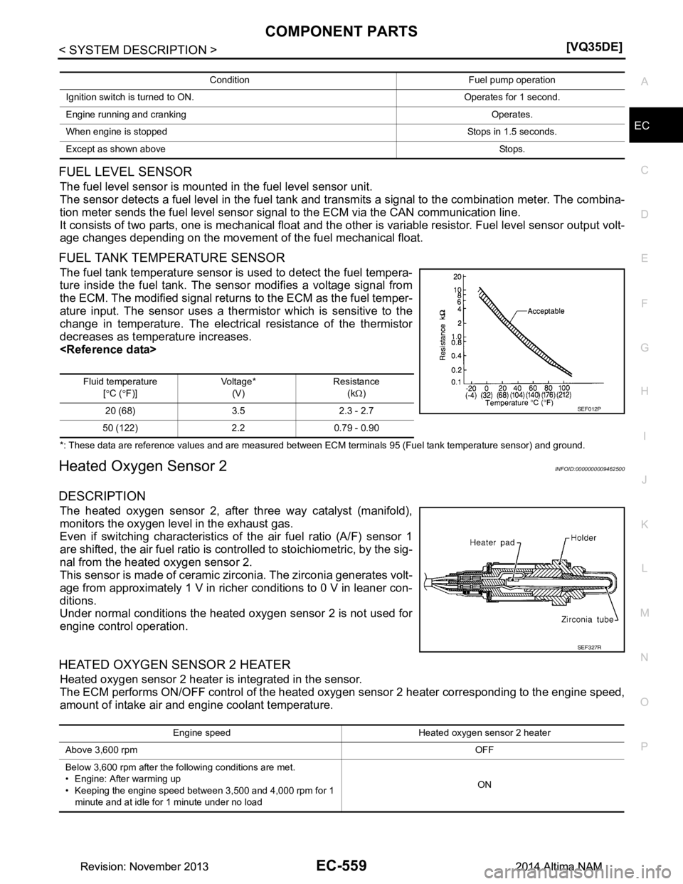
The fuel tank temperature sensor is used to detect the fuel tempera-
ture inside the fuel tank. The sensor modifies a voltage signal from
the ECM. The modified signal returns to the ECM as the fuel temper-
ature input. The sensor uses a ther mistor which is sensitive to the
change in temperature. The electrical resistance of the thermistor
decreases as temperature increases.
*: These data are reference values and are measured between ECM terminals 95 (Fuel tank temperature sensor) and ground.
Heated Oxygen Sensor 2INFOID:0000000009462500
DESCRIPTION
The heated oxygen sensor 2, after three way catalyst (manifold),
monitors the oxygen level in the exhaust gas.
Even if switching characteristics of the air fuel ratio (A/F) sensor 1
are shifted, the air fuel ratio is c ontrolled to stoichiometric, by the sig-
nal from the heated oxygen sensor 2.
This sensor is made of ceramic zirconia. The zirconia generates volt-
age from approximately 1 V in richer conditions to 0 V in leaner con-
ditions.
Under normal conditions the heated oxygen sensor 2 is not used for
engine control operation.
HEATED OXYGEN SENSOR 2 HEATER
Heated oxygen sensor 2 heater is integrated in the sensor.
The ECM performs ON/OFF control of the heated oxygen sensor 2 heater corresponding to the engine speed,
amount of intake air and engine coolant temperature.
Condition Fuel pump operation
Ignition switch is turned to ON. Operates for 1 second.
Engine running and cranking Operates.
When engine is stopped Stops in 1.5 seconds.
Except as shown above Sto ps .
Fluid temperature
[° C ( °F)] Voltage*
(V) Resistance
(kΩ)
20 (68) 3.5 2.3 - 2.7
50 (122) 2.2 0.79 - 0.90
SEF012P
SEF327R
Engine speed Heated oxygen sensor 2 heater
Above 3,600 rpm OFF
Below 3,600 rpm after the following conditions are met.
• Engine: After warming up
• Keeping the engine speed between 3,500 and 4,000 rpm for 1
minute and at idle for 1 minute under no load ON
Revision: November 20132014 Altima NAMRevision: November 20132014 Altima NAM
Page 1604 of 4801
EC-604
< SYSTEM DESCRIPTION >[VQ35DE]
DIAGNOSIS SYSTEM (ECM)
EVAP SYS PRES VThe signal voltage of EVAP control
system pressure sensor is dis-
played.
FUEL LEVEL SE V ×The signal voltage of the fuel level
sensor is displayed.
START SIGNAL On/Off Indicates start signal status [On/Off]
computed by the ECM according to
the signals of engine speed and bat-
tery voltage. After starting the engine, [Off] is dis-
played regardless of the starter sig-
nal.
CLSD THL POS On/Off ××Indicates idle position [On/Off] com-
puted by ECM according to the ac-
celerator pedal position sensor
signal.
AIR COND SIG On/Off ××Indicates [On/Off] condition of the air
conditioner switch as determined by
the air conditioner signal.
PW/ST SIGNAL On/Off ××[On/Off] condition of the power
steering system (determined by the
signal voltage of the power steering
pressure sensor) is indicated.
LOAD SIGNAL On/Off ××Indicates [On/Off] condition from the
electrical load signal.
• On: Rear window defogger switch
is ON and/or lighting switch is in
2nd position.
• Off: Both rear window defogger
switch and lighting switch are
OFF.
IGNITION SW On/Off ××Indicates [On/Off] condition from ig-
nition switch signal.
HEATER FAN SW On/Off ×Indicates [On/Off] condition from the
heater fan switch signal.
BRAKE SW On/Off Indicates [On/Off] condition from the
stop lamp switch signal.
INJ PULSE-B1 msec Indicates the actual fuel injection
pulse width compensated by ECM
according to the input signals. When the engine is stopped, a cer-
tain computed value is indicated.
INJ PULSE-B2
IGN TIMING BTDC ×Indicates the ignition timing comput-
ed by ECM according to the input
signals. When the engine is stopped, a cer-
tain value is indicated.
CAL/LD VALUE % “Calculated load value” indicates the
value of the current air flow divided
by peak air flow.
MASS AIRFLOW g/s Indicates the mass air flow comput-
ed by ECM according to the signal
voltage of the mass air flow sensor.
PURG VOL C/V % • Indicates the EVAP canister purge
volume control solenoid valve
control value computed by the
ECM according to the input sig-
nals.
• The opening becomes larger as the value increases.
Monitored item Unit
Monitor Item Selec-
tion
Description Remarks
ECU IN-
PUT SIG- NALS MAIN-
SIG-
NALS
Revision: November 20132014 Altima NAMRevision: November 20132014 Altima NAM
Page 1605 of 4801
DIAGNOSIS SYSTEM (ECM)EC-605
< SYSTEM DESCRIPTION > [VQ35DE]
C
D E
F
G H
I
J
K L
M A
EC
NP
O
INT/V TIM (B1)
°CA Indicates [
°CA] of intake camshaft
advance angle.
INT/V TIM (B2)
INT/V SOL(B1)
% • The control value of the intake
valve timing control solenoid valve
(determined by ECM according to
the input signals) is indicated.
• The advance angle becomes larg-
er as the value increases.
INT/V SOL(B2)
VIAS S/V-1 On/Off The control condition of the VIAS
control solenoid valve 1 (determined
by ECM according to the input sig-
nals) is indicated.
• On: VIAS control solenoid valve 1 is operating.
• Off: VIAS control solenoid valve 1 is not operating.
VIAS S/V-2 On/Off The control condition of the VIAS
control solenoid valve 2 (determined
by ECM according to the input sig-
nals) is indicated.
• On: VIAS control solenoid valve 2
is operating.
• Off: VIAS control solenoid valve 2 is not operating.
AIR COND RLY On/Off The air conditioner
relay control con-
dition (determined by ECM accord-
ing to the input signals) is indicated.
ENGINE MOUNT IDLE/
TRVL The control condition of the electron-
ic controlled engine mount (deter-
mined by ECM according to the
input signals) is indicated.
• IDLE: Engine speed is below 950
rpm
• TRVL: Engine speed is above 950 rpm
FUEL PUMP RLY On/Off Indicates the fuel pump relay control
condition determined by ECM ac-
cording to the input signals.
VENT CONT/V On/Off The control condition of the EVAP
canister vent control valve (deter-
mined by ECM according to the in-
put signals) is indicated.
• On: Closed
• Off: Open
THRTL RELAY On/Off Indicates the throttle control motor
relay control condition determined
by the ECM according to the input
signals.
A/F S1 HTR(B1)
% • Air fuel ratio (A/F) sensor 1 heater
control value computed by ECM
according to the input signals.
• The current flow to the heater be-
comes larger as the value increas-
es.
A/F S1 HTR(B2) Monitored item Unit
Monitor Item Selec-
tion
Description Remarks
ECU IN-
PUT SIG- NALS MAIN-
SIG-
NALS
Revision: November 20132014 Altima NAMRevision: November 20132014 Altima NAM
Page 1606 of 4801
EC-606
< SYSTEM DESCRIPTION >[VQ35DE]
DIAGNOSIS SYSTEM (ECM)
COOLING FANHI/MID/
LOW/OFF • The control condition of the cool-
ing fan (determined by ECM ac-
cording to the input signals) is
indicated.
HI: High speed operation
MID: Middle speed operation
LOW: Low speed operation
OFF: Stop
HO2S2 HTR (B1)
On/Off Indicates [On/Off] condition of heat-
ed oxygen sensor 2 heater deter-
mined by ECM according to the
input signals.
HO2S2 HTR (B2)
ALT DUTY SIG On/Off The control condition of the power
generation voltage variable control
(determined by ECM according to
the input signals) is indicated.
• On: Power generation voltage variable control is active.
• Off: Power generation voltage
variable control is inactive.
I/P PULLY SPD rpm Indicates the engine speed comput-
ed from the input speed sensor sig-
nal.
VEHICLE SPEED km/h or
mph The vehicle speed computed from
the vehicle speed signal sent from
TCM is displayed.
IDL A/V LEARN YET/
CMPLT Displays the condition of idle air vol-
ume learning
• Yet: Idle Air Volume Learning has not been performed yet.
• Cmplt: Idle Air Volume Learning
has already been performed suc-
cessfully.
TRVL AFTER MIL km or
mile Distance traveled while MIL is acti-
vated.
ENG OIL TEMP °C or °F The engine oil temperature (deter-
mined by the signal voltage of the
engine oil temperature sensor) is
displayed.
VHCL SPEED SE km/h or
mph The vehicle speed computed from
the vehicle speed signal sent from
combination meter is displayed.
SET VHCL SPD km/h or
mph • The preset vehicle speed is dis-
played.
MAIN SW On/Off Indicates [On/Off] condition from
MAIN switch signal.
CANCEL SW On/Off Indicates [On/Off] condition from
CANCEL switch signal.
RESUME/ACC SW On/Off Indicates [On/Off] condition from
RESUME/ACCELERATE switch sig-
nal.
SET SW On/Off Indicates [On/Off] condition from
SET/COAST switch signal.
Monitored item Unit
Monitor Item Selec-
tion
Description Remarks
ECU IN-
PUT SIG- NALS MAIN-
SIG-
NALS
Revision: November 20132014 Altima NAMRevision: November 20132014 Altima NAM
Page 1614 of 4801
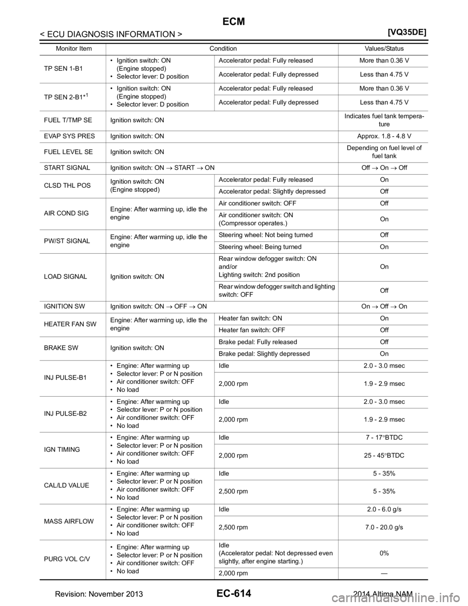
EC-614
< ECU DIAGNOSIS INFORMATION >[VQ35DE]
ECM
TP SEN 1-B1• Ignition switch: ON
(Engine stopped)
• Selector lever: D position Accelerator pedal: Fully re
leased More than 0.36 V
Accelerator pedal: Fully depressed Less than 4.75 V
TP SEN 2-B1*
1• Ignition switch: ON (Engine stopped)
• Selector lever: D position Accelerator pedal: Fully re
leased More than 0.36 V
Accelerator pedal: Fully depressed Less than 4.75 V
FUEL T/TMP SE Ignition switch: ON Indicates fuel tank tempera-
ture
EVAP SYS PRES Ignition switch: ON Approx. 1.8 - 4.8 V
FUEL LEVEL SE Ignition switch: ON Depending on fuel level of
fuel tank
START SIGNAL Ignition switch: ON → START → ON Off → On → Off
CLSD THL POS Ignition switch: ON
(Engine stopped) Accelerator pedal:
Fully released On
Accelerator pedal: Slightly depressed Off
AIR COND SIG Engine: After warming up, idle the
engine Air conditioner switch: OFF Off
Air conditioner switch: ON
(Compressor operates.) On
PW/ST SIGNAL Engine: After warming up, idle the
engine Steering wheel: Not being turned Off
Steering wheel: Being turned On
LOAD SIGNAL Ignition switch: ON Rear window defogger switch: ON
and/or
Lighting switch: 2nd position On
Rear window defogger switch and lighting
switch: OFF Off
IGNITION SW Ignition switch: ON → OFF → ON On → Off → On
HEATER FAN SW Engine: After warming up, idle the
engine Heater fan switch: ON On
Heater fan switch: OFF Off
BRAKE SW Ignition switch: ON Brake pedal: Fully released Off
Brake pedal: Slightly depressed On
INJ PULSE-B1 • Engine: After warming up
• Selector lever: P or N position
• Air conditioner switch: OFF
•No load Idle 2.0 - 3.0 msec
2,000 rpm 1.9 - 2.9 msec
INJ PULSE-B2 • Engine: After warming up
• Selector lever: P or N position
• Air conditioner switch: OFF
•No load Idle 2.0 - 3.0 msec
2,000 rpm 1.9 - 2.9 msec
IGN TIMING • Engine: After warming up
• Selector lever: P or N position
• Air conditioner switch: OFF
•No load Idle 7 - 17
°BTDC
2,000 rpm 25 - 45 °BTDC
CAL/LD VALUE • Engine: After warming up
• Selector lever: P or N position
• Air conditioner switch: OFF
•No load Idle 5 - 35%
2,500 rpm 5 - 35%
MASS AIRFLOW • Engine: After warming up
• Selector lever: P or N position
• Air conditioner switch: OFF
•No load Idle 2.0 - 6.0 g/s
2,500 rpm 7.0 - 20.0 g/s
PURG VOL C/V • Engine: After warming up
• Selector lever: P or N position
• Air conditioner switch: OFF
•No load Idle
(Accelerator pedal: Not depressed even
slightly, after engine starting.) 0%
2,000 rpm —
Monitor Item Condition Values/Status
Revision: November 20132014 Altima NAMRevision: November 20132014 Altima NAM
Page 1619 of 4801
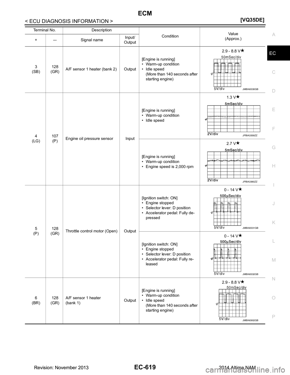
ECM
EC-619
< ECU DIAGNOSIS INFORMATION > [VQ35DE]
C
D E
F
G H
I
J
K L
M A
EC
NP
O
3
(SB) 128
(GR) A/F sensor 1 heater (bank 2) Output [Engine is running]
• Warm-up condition
• Idle speed (More than 140 seconds after
starting engine) 2.9 - 8.8 V
4
(LG) 107
(P) Engine oil pressure sensor Input [Engine is running]
• Warm-up condition
• Idle speed 1.3 V
[Engine is running]
• Warm-up condition
• Engine speed is 2,000 rpm 2.7 V
5
(P) 128
(GR) Throttle control motor (Open) Output [Ignition switch: ON]
• Engine stopped
• Selector lever: D position
• Accelerator pedal: Fully de-
pressed 0 - 14 V
[Ignition switch: ON]
• Engine stopped
• Selector lever: D position
• Accelerator pedal: Fully re- leased 0 - 14 V
6
(BR) 128
(GR) A/F sensor 1 heater
(bank 1) Output[Engine is running]
• Warm-up condition
• Idle speed
(More than 140 seconds after
starting engine) 2.9 - 8.8 V
Terminal No. Description
ConditionVa l u e
(Approx.)
+ -– Signal name Input/
Output
JMBIA0030GB
JPBIA3359ZZ
JPBIA3360ZZ
JMBIA0031GB
JMBIA0032GB
JMBIA0902GB
Revision: November 20132014 Altima NAMRevision: November 20132014 Altima NAM
Page 1630 of 4801
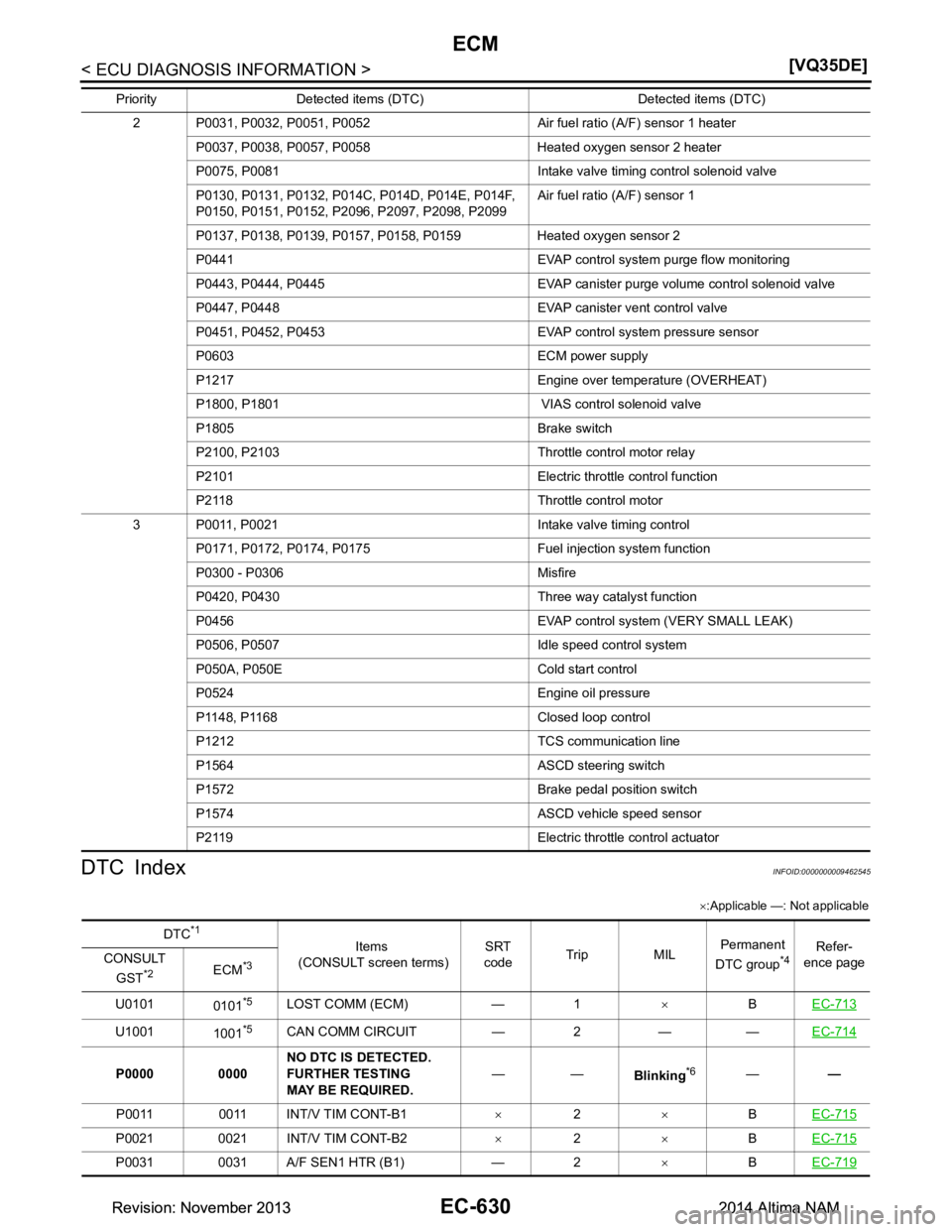
EC-630
< ECU DIAGNOSIS INFORMATION >[VQ35DE]
ECM
DTC Index
INFOID:0000000009462545
× :Applicable —: Not applicable
2 P0031, P0032, P0051, P0052 Air fuel ratio (A/F) sensor 1 heater
P0037, P0038, P0057, P0058 Heated oxygen sensor 2 heater
P0075, P0081 Intake valve timing control solenoid valve
P0130, P0131, P0132, P014 C, P014D, P014E, P014F,
P0150, P0151, P0152, P209 6, P2097, P2098, P2099 Air fuel ratio (A/F) sensor 1
P0137, P0138, P0139, P0157, P0158, P0159 Heated oxygen sensor 2
P0441 EVAP control system purge flow monitoring
P0443, P0444, P0445 EVAP canister purge volume control solenoid valve
P0447, P0448 EVAP canister vent control valve
P0451, P0452, P0453 EVAP control system pressure sensor
P0603 ECM power supply
P1217 Engine over temperature (OVERHEAT)
P1800, P1801 VIAS cont rol solenoid valve
P1805 Brake switch
P2100, P2103 Throttle control motor relay
P2101 Electric throttle control function
P2118 Throttle control motor
3 P0011, P0021 Intake valve timing control P0171, P0172, P0174, P0175 Fuel injection system function
P0300 - P0306 Misfire
P0420, P0430 Three way catalyst function
P0456 EVAP control syst em (VERY SMALL LEAK)
P0506, P0507 Idle speed control system
P050A, P050E Cold start control
P0524 Engine oil pressure
P1148, P1168 Closed loop control
P1212 TCS communication line
P1564 ASCD steering switch
P1572 Brake pedal position switch
P1574 ASCD vehicle speed sensor
P2119 Electric throttle control actuator
Priority Detected items (DTC) Detected items (DTC)
DTC*1
Items
(CONSULT screen terms) SRT
code Trip MIL Permanent
DTC group*4Refer-
ence page
CONSULT
GST
*2ECM*3
U0101 0101*5LOST COMM (ECM) — 1 ×BEC-713
U1001
1001*5CAN COMM CIRCUIT — 2 — — EC-714
P0000 0000NO DTC IS DETECTED.
FURTHER TESTING
MAY BE REQUIRED. ——
Blinking*6——
P0011 0011 INT/V TIM CONT-B1 ×2 ×BEC-715
P0021 0021 INT/V TIM CONT-B2 ×2 ×BEC-715
P0031 0031 A/F SEN1 HTR (B1) — 2 ×BEC-719
Revision: November 20132014 Altima NAMRevision: November 20132014 Altima NAM
Page 1639 of 4801
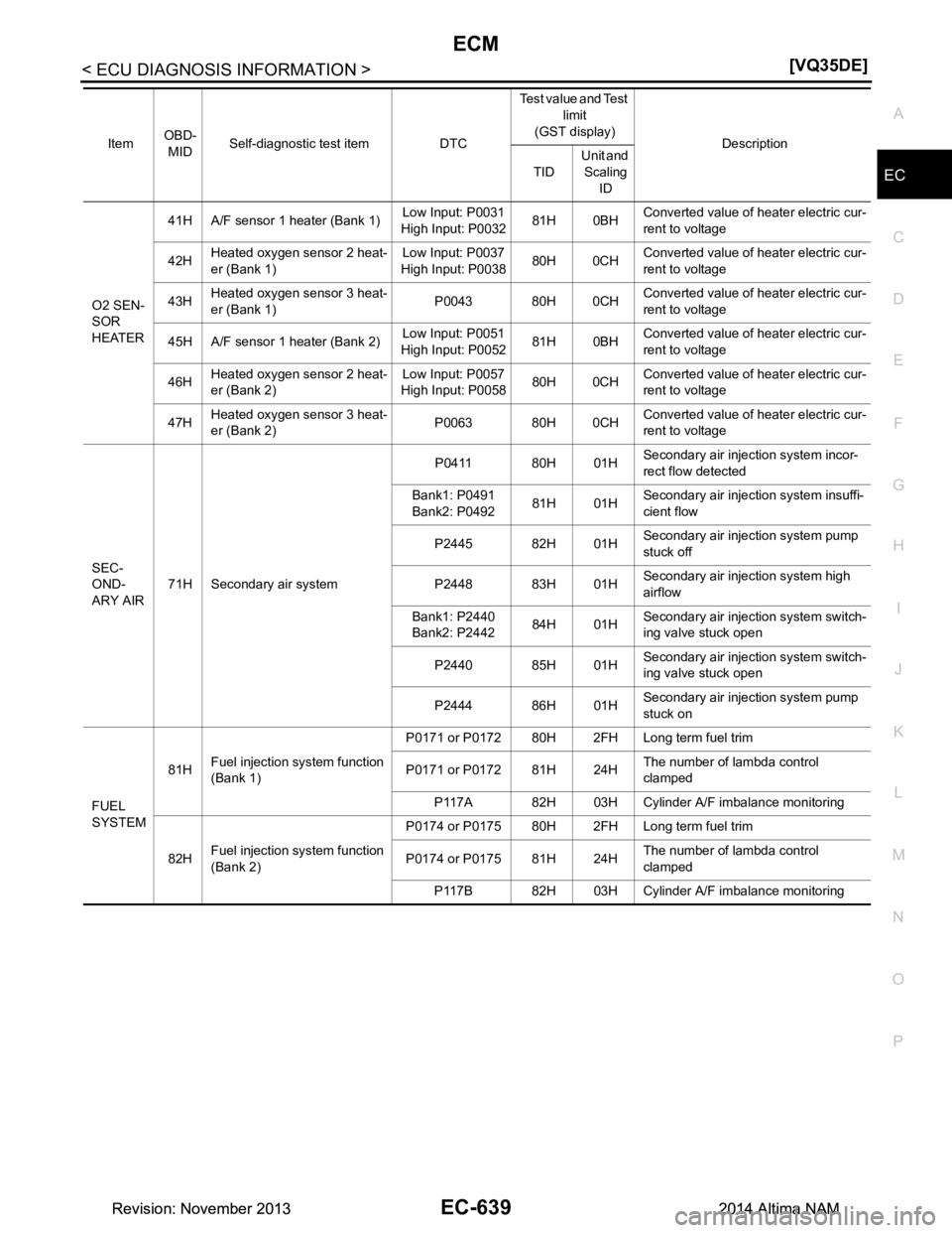
ECM
EC-639
< ECU DIAGNOSIS INFORMATION > [VQ35DE]
C
D E
F
G H
I
J
K L
M A
EC
NP
O
O2 SEN-
SOR
HEATER 41H A/F sensor 1 heater (Bank 1)
Low Input: P0031
High Input: P0032 81H 0BHConverted value of heater electric cur-
rent to voltage
42H Heated oxygen sensor 2 heat-
er (Bank 1) Low Input: P0037
High Input: P0038 80H 0CH
Converted value of heater electric cur-
rent to voltage
43H Heated oxygen sensor 3 heat-
er (Bank 1) P0043 80H 0CHConverted value of heater electric cur-
rent to voltage
45H A/F sensor 1 heater (Bank 2) Low Input: P0051
High Input: P0052 81H 0BHConverted value of heater electric cur-
rent to voltage
46H Heated oxygen sensor 2 heat-
er (Bank 2) Low Input: P0057
High Input: P0058 80H 0CH
Converted value of heater electric cur-
rent to voltage
47H Heated oxygen sensor 3 heat-
er (Bank 2) P0063 80H 0CHConverted value of heater electric cur-
rent to voltage
SEC-
OND-
ARY AIR 71H Secondary air system P0411 80H 01H
Secondary air injection system incor-
rect flow detected
Bank1: P0491
Bank2: P0492 81H 01H
Secondary air injection system insuffi-
cient flow
P2445 82H 01H Secondary air injection system pump
stuck off
P2448 83H 01H Secondary air injection system high
airflow
Bank1: P2440
Bank2: P2442 84H 01H
Secondary air injection system switch-
ing valve stuck open
P2440 85H 01H Secondary air injection system switch-
ing valve stuck open
P2444 86H 01H Secondary air injection system pump
stuck on
FUEL
SYSTEM 81H
Fuel injection system function
(Bank 1) P0171 or P0172 80H 2FH Long term fuel trim
P0171 or P0172 81H 24H The number of lambda control
clamped
P117A 82H 03H Cylinder A/F imbalance monitoring
82H Fuel injection system function
(Bank 2) P0174 or P0175 80H 2FH Long term fuel trim
P0174 or P0175 81H 24H The number of lambda control
clamped
P117B 82H 03H Cylinder A/F imbalance monitoring
Item
OBD-
MID Self-diagnostic test item DTC Test value and Test
limit
(GST display) Description
TID Unit and
Scaling ID
Revision: November 20132014 Altima NAMRevision: November 20132014 Altima NAM
Page 1719 of 4801
P0031, P0032, P0051, P0052 A/F SENSOR 1 HEATER
EC-719
< DTC/CIRCUIT DIAGNOSIS > [VQ35DE]
C
D E
F
G H
I
J
K L
M A
EC
NP
O
P0031, P0032, P0051, P0052
A/F SENSOR 1 HEATER
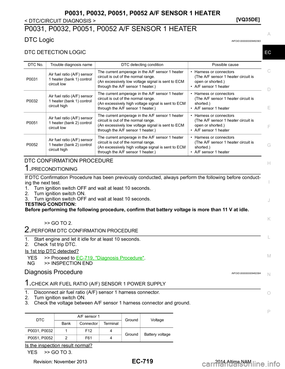
DTC LogicINFOID:0000000009462583
DTC DETECTION LOGIC
DTC CONFIRMATION PROCEDURE
1.PRECONDITIONING
If DTC Confirmation Procedure has been previously conduc ted, always perform the following before conduct-
ing the next test.
1. Turn ignition switch OFF and wait at least 10 seconds.
2. Turn ignition switch ON.
3. Turn ignition switch OFF and wait at least 10 seconds.
TESTING CONDITION:
Before performing the following procedure, confirm that battery voltage is more than 11 V at idle.
>> GO TO 2.
2.PERFORM DTC CONFIRMATION PROCEDURE
1. Start engine and let it idle for at least 10 seconds.
2. Check 1st trip DTC.
Is 1st trip DTC detected?
YES >> Proceed to EC-719, "Diagnosis Procedure".
NG >> INSPECTION END
Diagnosis ProcedureINFOID:0000000009462584
1.CHECK AIR FUEL RATIO (A/F) SENSOR 1 POWER SUPPLY
1. Disconnect air fuel ratio (A/F) sensor 1 harness connector.
2. Turn ignition switch ON.
3. Check the voltage between A/F sensor 1 harness connector and ground.
Is the inspection result normal?
YES >> GO TO 3.
DTC No. Trouble diagnosis name DTC detecting condition Possible cause
P0031 Air fuel ratio (A/F) sensor
1 heater (bank 1) control
circuit low The current amperage in the A/F sensor 1 heater
circuit is out of the normal range.
(An excessively low voltage signal is sent to ECM
through the A/F sensor 1 heater.) • Harness or connectors
(The A/F sensor 1 heater circuit is
open or shorted.)
• A/F sensor 1 heater
P0032 Air fuel ratio (A/F) sensor
1 heater (bank 1) control
circuit high The current amperage in the A/F sensor 1 heater
circuit is out of the normal range.
(An excessively high voltage signal is sent to ECM
through the A/F sensor 1 heater.) • Harness or connectors
(The A/F sensor 1 heater circuit is
shorted.)
• A/F sensor 1 heater
P0051 Air fuel ratio (A/F) sensor
1 heater (bank 2) control
circuit low The current amperage in the A/F sensor 1 heater
circuit is out of the normal range.
(An excessively low voltage signal is sent to ECM
through the A/F sensor 1 heater.) • Harness or connectors
(The A/F sensor 1 heater circuit is
open or shorted.)
• A/F sensor 1 heater
P0052 Air fuel ratio (A/F) sensor
1 heater (bank 2) control
circuit high The current amperage in the A/F sensor 1 heater
circuit is out of the normal range.
(An excessively high voltage signal is sent to ECM
through the A/F sensor 1 heater.) • Harness or connectors
(The A/F sensor 1 heater circuit is
shorted.)
• A/F sensor 1 heater
DTC A/F sensor 1
Ground Voltage
Bank Connector Terminal
P0031, P0032 1 F12 4 Ground Battery voltage
P0051, P0052 2 F61 4
Revision: November 20132014 Altima NAMRevision: November 20132014 Altima NAM
Page 1720 of 4801
EC-720
< DTC/CIRCUIT DIAGNOSIS >[VQ35DE]
P0031, P0032, P0051, P00
52 A/F SENSOR 1 HEATER
NO >> GO TO 2.
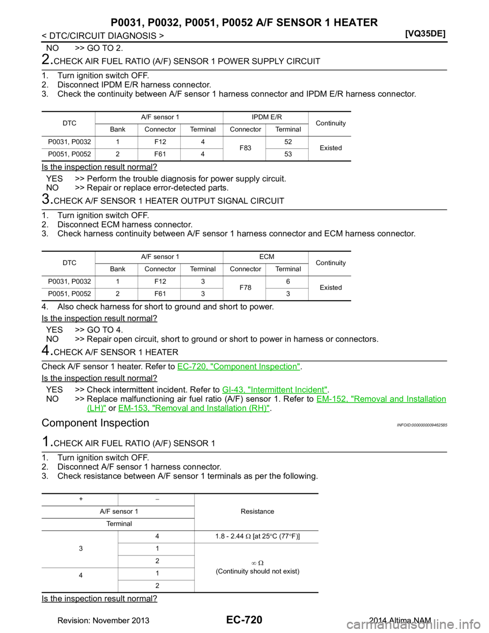
2.CHECK AIR FUEL RATIO (A/F) SENSOR 1 POWER SUPPLY CIRCUIT
1. Turn ignition switch OFF.
2. Disconnect IPDM E/R harness connector.
3. Check the continuity between A/F sensor 1 harness connector and IPDM E/R harness connector.
Is the inspection result normal?
YES >> Perform the trouble diagnosis for power supply circuit.
NO >> Repair or replace error-detected parts.
3.CHECK A/F SENSOR 1 HEATER OUTPUT SIGNAL CIRCUIT
1. Turn ignition switch OFF.
2. Disconnect ECM harness connector.
3. Check harness continuity between A/F sensor 1 harness connector and ECM harness connector.
4. Also check harness for short to ground and short to power.
Is the inspection result normal?
YES >> GO TO 4.
NO >> Repair open circuit, short to ground or short to power in harness or connectors.
4.CHECK A/F SENSOR 1 HEATER
Check A/F sensor 1 heater. Refer to EC-720, "Component Inspection"
.
Is the inspection result normal?
YES >> Check intermittent incident. Refer to GI-43, "Intermittent Incident".
NO >> Replace malfunctioning air fuel ratio (A/F) sensor 1. Refer to EM-152, "Removal and Installation
(LH)" or EM-153, "Removal and Installation (RH)".
Component InspectionINFOID:0000000009462585
1.CHECK AIR FUEL RATIO (A/F) SENSOR 1
1. Turn ignition switch OFF.
2. Disconnect A/F sensor 1 harness connector.
3. Check resistance between A/F sensor 1 terminals as per the following.
Is the inspection result normal?
DTC A/F sensor 1 IPDM E/R
Continuity
Bank Connector Terminal Connector Terminal
P0031, P0032 1 F12 4 F8352
Existed
P0051, P0052 2 F61 4 53
DTC A/F sensor 1 ECM
Continuity
Bank Connector Terminal Connector Terminal
P0031, P0032 1 F12 3 F786
Existed
P0051, P0052 2 F61 3 3
+ −
Resistance
A/F sensor 1
Te r m i n a l
3 4 1.8 - 2.44
Ω [at 25 °C (77 °F)]
1
∞ Ω
(Continuity should not exist)
2
4 1
2
Revision: November 20132014 Altima NAMRevision: November 20132014 Altima NAM