Heater NISSAN TEANA 2014 Service Manual
[x] Cancel search | Manufacturer: NISSAN, Model Year: 2014, Model line: TEANA, Model: NISSAN TEANA 2014Pages: 4801, PDF Size: 51.2 MB
Page 4616 of 4801
CVT OIL WARMER SYSTEMTM-401
< REMOVAL AND INSTALLATION > [CVT: RE0F10E]
C
EF
G H
I
J
K L
M A
B
TM
N
O P
2. Remove engine room cover. Refer to EM-28, "Removal and Installation".
3. Remove front air duct and air cleaner case assembly. Refer to EM-29, "Removal and Installation"
.
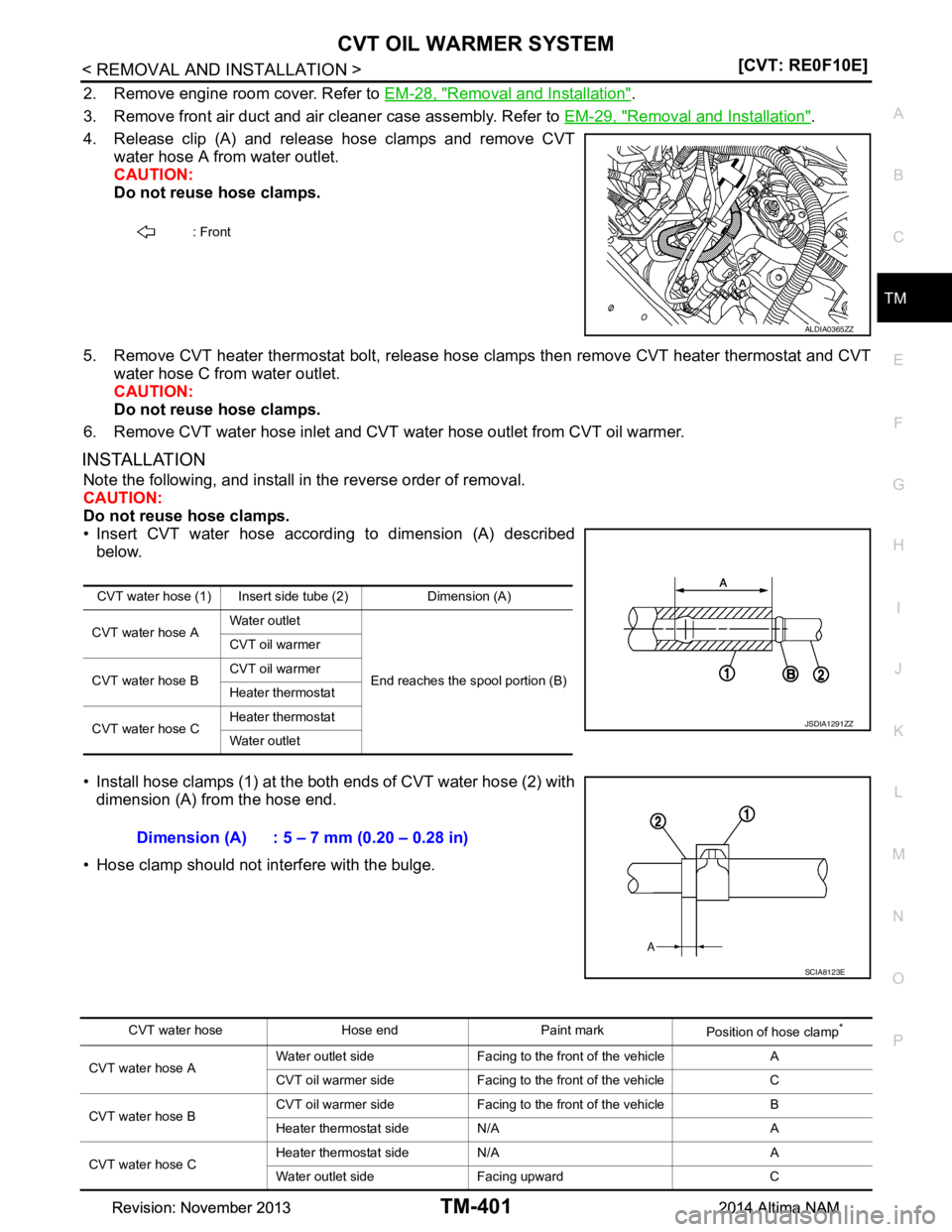
4. Release clip (A) and release hose clamps and remove CVT water hose A from water outlet.
CAUTION:
Do not reuse hose clamps.
5. Remove CVT heater thermostat bolt, release hose clamps then remove CVT heater thermostat and CVT
water hose C from water outlet.
CAUTION:
Do not reuse hose clamps.
6. Remove CVT water hose inlet and CVT water hose outlet from CVT oil warmer.
INSTALLATION
Note the following, and install in the reverse order of removal.
CAUTION:
Do not reuse hose clamps.
• Insert CVT water hose according to dimension (A) described below.
• Install hose clamps (1) at the both ends of CVT water hose (2) with dimension (A) from the hose end.
• Hose clamp should not interfere with the bulge.
: Front
ALDIA0365ZZ
CVT water hose (1) Insert side tube (2) Dimension (A)
CVT water hose A Water outlet
End reaches the spool portion (B)
CVT oil warmer
CVT water hose B CVT oil warmer
Heater thermostat
CVT water hose C Heater thermostat
Water outlet
JSDIA1291ZZ
Dimension (A) : 5 – 7 mm (0.20 – 0.28 in)
SCIA8123E
CVT water hose Hose end Paint mark
Position of hose clamp*
CVT water hose AWater outlet side Facing to the front of the vehicle A
CVT oil warmer side Facing to the front of the vehicle C
CVT water hose B CVT oil warmer side Facing to the front of the vehicle B
Heater thermostat side N/A A
CVT water hose C Heater thermostat side N/A A
Water outlet side Facing upward C
Revision: November 20132014 Altima NAMRevision: November 20132014 Altima NAM
Page 4628 of 4801
SERVICE DATA AND SPECIFICATIONS (SDS)TM-413
< SERVICE DATA AND SPECIFICATIONS (SDS) [CVT: RE0F10E]
C
EF
G H
I
J
K L
M A
B
TM
N
O P
SERVICE DATA AND SPECIFICATIONS (SDS)
SERVICE DATA AND SPECIFICATIONS (SDS)
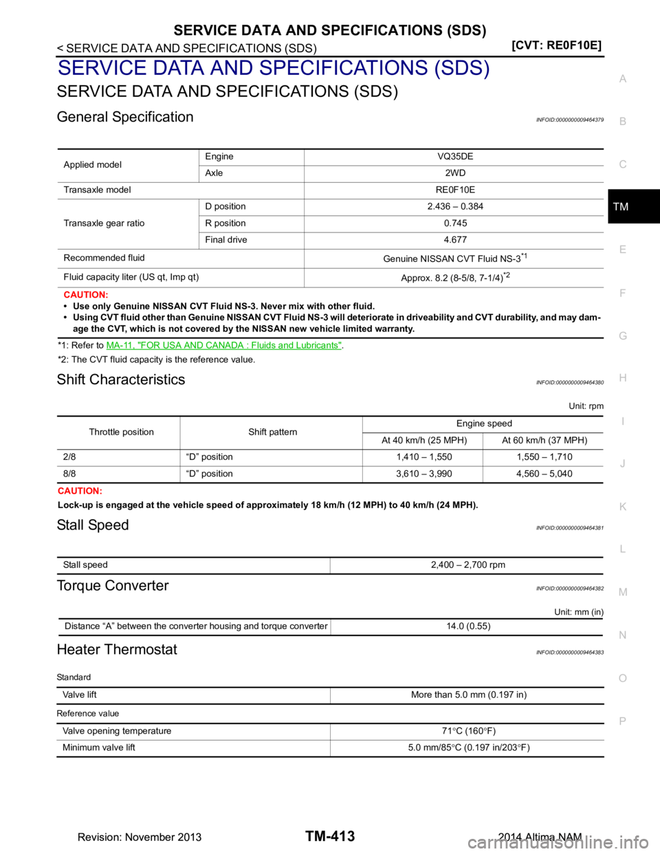
General SpecificationINFOID:0000000009464379
*1: Refer to MA-11, "FOR USA AND CANADA : Fluids and Lubricants".
*2: The CVT fluid capacity is the reference value.
Shift CharacteristicsINFOID:0000000009464380
Unit: rpm
CAUTION:
Lock-up is engaged at the vehicle speed of approximately 18 km/h (12 MPH) to 40 km/h (24 MPH).
Stall SpeedINFOID:0000000009464381
Torque ConverterINFOID:0000000009464382
Unit: mm (in)
Heater ThermostatINFOID:0000000009464383
Standard
Reference value
Applied model Engine VQ35DE
Axle 2WD
Transaxle model RE0F10E
Transaxle gear ratio D position 2.436 – 0.384
R position 0.745
Final drive 4.677
Recommended fluid Genuine NISSAN CVT Fluid NS-3
*1
Fluid capacity liter (US qt, Imp qt) Approx. 8.2 (8-5/8, 7-1/4)*2
CAUTION:
• Use only Genuine NISSAN CVT Fluid NS-3. Never mix with other fluid.
• Using CVT fluid other than Genuine NISSAN CVT Fluid NS-3 will deteriorate in driveability and CVT durability, and may dam-
age the CVT, which is not covered by the NISSAN new vehicle limited warranty.
Throttle position Shift pattern Engine speed
At 40 km/h (25 MPH) At 60 km/h (37 MPH)
2/8 “D” position 1,410 – 1,550 1,550 – 1,710
8/8 “D” position 3,610 – 3,990 4,560 – 5,040
Stall speed 2,400 – 2,700 rpm
Distance “A” between the converter housing and torque converter 14.0 (0.55)
Va l v e l i f tMore than 5.0 mm (0.197 in)
Valve opening temperature 71 °C (160 °F)
Minimum valve lift 5.0 mm/85 °C (0.197 in/203 °F)
Revision: November 20132014 Altima NAMRevision: November 20132014 Altima NAM
Page 4629 of 4801
VTL-1
VENTILATION, HEATER & AIR CONDITIONER
C
D E
F
G H
J
K L
M
SECTION VTL
A
B
VTL
N
O P
CONTENTS
VENTILATION SYSTEM
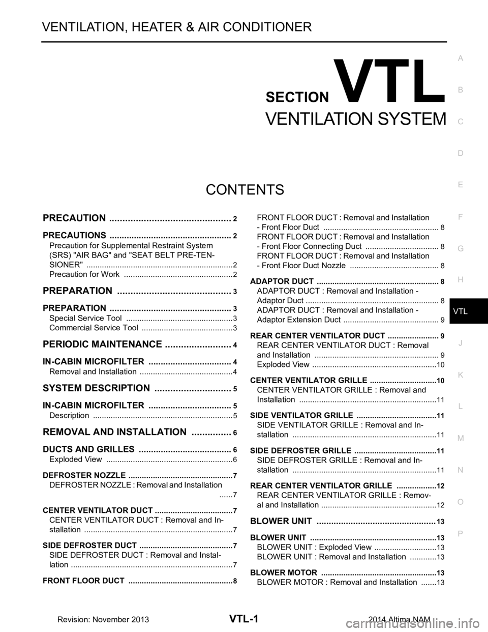
PRECAUTION ................ ...............................2
PRECAUTIONS .............................................. .....2
Precaution for Supplemental Restraint System
(SRS) "AIR BAG" and "SEAT BELT PRE-TEN-
SIONER" ............................................................. ......
2
Precaution for Work ..................................................2
PREPARATION ............................................3
PREPARATION .............................................. .....3
Special Service Tool ........................................... ......3
Commercial Service Tool ..........................................3
PERIODIC MAINTENANCE ..........................4
IN-CABIN MICROFILTER .............................. .....4
Removal and Installation ...........................................4
SYSTEM DESCRIPTION . .............................5
IN-CABIN MICROFILTER .............................. .....5
Description .......................................................... ......5
REMOVAL AND INSTALLATION ................6
DUCTS AND GRILLES .................................. .....6
Exploded View .................................................... ......6
DEFROSTER NOZZLE .......................................... ......7
DEFROSTER NOZZLE : Removal and Installation
......
7
CENTER VENTILATOR DUCT .............................. ......7
CENTER VENTILATOR DUCT : Removal and In-
stallation .............................................................. ......
7
SIDE DEFROSTER DUCT ..................................... ......7
SIDE DEFROSTER DUCT : Removal and Instal-
lation .................................................................... ......
7
FRONT FLOOR DUCT .......................................... ......8
FRONT FLOOR DUCT : Removal and Installation
- Front Floor Duct ................................................ .....
8
FRONT FLOOR DUCT : Removal and Installation
- Front Floor Connecting Duct ............................. .....
8
FRONT FLOOR DUCT : Removal and Installation
- Front Floor Duct Nozzle .................................... .....
8
ADAPTOR DUCT ................................................... .....8
ADAPTOR DUCT : Removal and Installation -
Adaptor Duct ........................................................ .....
8
ADAPTOR DUCT : Removal and Installation -
Adaptor Extension Duct ....................................... .....
9
REAR CENTER VENTILATOR DUCT ................... .....9
REAR CENTER VENTILATOR DUCT : Removal
and Installation .................................................... .....
9
Exploded View .........................................................10
CENTER VENTILATOR GRILLE ........................... ....10
CENTER VENTILATOR GRILLE : Removal and
Installation ........................................................... ....
11
SIDE VENTILATOR GRILLE ................................. ....11
SIDE VENTILATOR GRILLE : Removal and In-
stallation .............................................................. ....
11
SIDE DEFROSTER GRILLE .................................. ....11
SIDE DEFROSTER GRILLE : Removal and In-
stallation .............................................................. ....
11
REAR CENTER VENTILATOR GRILLE ............... ....12
REAR CENTER VENTILATOR GRILLE : Remov-
al and Installation ................................................. ....
12
BLOWER UNIT .................................................13
BLOWER UNIT ...................................................... ....13
BLOWER UNIT : Exploded View .............................13
BLOWER UNIT : Removal and Installation .............13
BLOWER MOTOR ................................................. ....13
BLOWER MOTOR : Removal and Installation ........13
Revision: November 20132014 Altima NAM