oil type NISSAN TEANA 2014 User Guide
[x] Cancel search | Manufacturer: NISSAN, Model Year: 2014, Model line: TEANA, Model: NISSAN TEANA 2014Pages: 4801, PDF Size: 51.2 MB
Page 1335 of 4801

P0420 THREE WAY CATALYST FUNCTIONEC-335
< DTC/CIRCUIT DIAGNOSIS > [QR25DE]
C
D E
F
G H
I
J
K L
M A
EC
NP
O
8. Crank engine for 5 seconds or more to remove combustion gas in the cylinder.
9. Connect spark plug and harness connector to ignition coil.
10. Fix ignition coil using a rope etc. with gap of 13 - 17 mm (0.52 -
0.66 in) between the edge of the spark plug and grounded metal
portion as shown in the figure.
11. Crank engine for about 3 seconds, and check whether spark is
generated between the spark plug and the grounded metal por-
tion.
CAUTION:
• Do not approach to the spar k plug and the ignition coil
within 50 cm (19.7 in). Be car eful not to get an electrical
shock while checking, becau se the electrical discharge
voltage becomes 20 kV or more.
• It might cause to damage the igni tion coil if the gap of more than 17 mm (0.66 in) is taken.
NOTE:
When the gap is less than 13 mm (0.52 in), the sp ark might be generated even if the coil is mal-
functioning.
Is the inspection result normal?
YES >> GO TO 10.
NO >> GO TO 7.
7.CHECK FUNCTION OF IGNITION COIL-2
1. Turn ignition switch OFF.
2. Disconnect spark plug and connect a known-good spark plug.
3. Crank engine for about 3 seconds, and recheck whether spark is generated between the spark plug and the grounded metal portion.
Is the inspection result normal?
YES >> GO TO 8.
NO >> Check ignition coil, power transistor and their circuits. Refer to EC-511, "Diagnosis Procedure"
.
8.CHECK SPARK PLUG
Check the initial spark plug for fouling, etc. Refer to EM-16,
"Removal and Installation".
Is the inspection result normal?
YES >> Replace spark plug(s) with standard type one(s). For spark plug type, refer to EM-111, "Standard and Limit"
.
NO >> Repair or clean spark plug. Refer to EM-16, "Removal
and Installation". Then GO TO 9
9.CHECK FUNCTION OF IGNITION COIL-3
1. Reconnect the initial spark plugs.
2. Crank engine for about 3 seconds, and recheck whether spark is generated between the spark plug and
the grounded portion.
Is the inspection result normal?
YES >> INSPECTION END
NO >> Replace spark plug(s) with standard type one(s). For spark plug type, refer to EM-111, "Standard
and Limit".
Spark should be generated.
JMBIA0066GB
Spark should be generated.
SEF156I
Spark should be generated.
Revision: November 20132014 Altima NAMRevision: November 20132014 Altima NAM
Page 1421 of 4801

P117A AIR FUEL RATIOEC-421
< DTC/CIRCUIT DIAGNOSIS > [QR25DE]
C
D E
F
G H
I
J
K L
M A
EC
NP
O
YES >> Check intermittent incident. Refer to
GI-43, "Intermittent Incident".
NO >> Check pistons, piston rings, valves, valve seats and cylinder head gaskets.
9.DETECT MALFUNCTIONING PART
Check fuel hoses and fuel tubes for clogging.
Is the inspection result normal?
YES >> Replace fuel filter and fuel pump assembly. Refer to FL-6, "Removal and Installation".
NO >> Repair or replace error-detected parts.
10.CHECK FUNCTION OF IGNITION COIL-2
1. Turn ignition switch OFF.
2. Disconnect spark plug and connect a non-malfunctioning spark plug.
3. Crank engine for approximately 3 seconds, and rec heck whether spark is generated between the spark
plug and the grounded metal portion.
Is the inspection result normal?
YES >> GO TO 11.
NO >> Check ignition coil, power trans istor and their circuits. Refer to EC-511, "Component Function
Check".
11 .CHECK SPARK PLUG
Check the initial spark plug for fouling, etc.
Is the inspection result normal?
YES >> 1. Repair or clean spark plug. Refer to EM-16,
"Removal and Installation".
2. GO TO 12.
NO >> Replace spark plug(s) with standard type one(s). For spark plug type, refer to EM-111, "Standard and Limit"
.
12.CHECK FUNCTION OF IGNITION COIL-3
1. Reconnect the initial spark plugs.
2. Crank engine for approximately 3 seconds, and rec heck whether spark is generated between the spark
plug and the grounded portion.
Is the inspection result normal?
YES >> Check intermittent incident. Refer to GI-43, "Intermittent Incident".
NO >> Replace spark plug(s) with standard type one(s). For spark plug type, refer to EM-111, "Standard
and Limit".
Spark should be generated.
SEF156I
Spark should be generated.
Revision: November 20132014 Altima NAMRevision: November 20132014 Altima NAM
Page 1562 of 4801

EC-562
< SYSTEM DESCRIPTION >[VQ35DE]
COMPONENT PARTS
Refrigerant Pressure Sensor
INFOID:0000000009462508
The refrigerant pressure sensor is installed at the c ondenser of the air conditioner system. The sensor uses an
electrostatic volume pressure transducer to convert refrigerant pressure to voltage. The voltage signal is sent
to ECM, and ECM controls cooling fan system.
Stop Lamp Switch & Brake Pedal Position SwitchINFOID:0000000009462509
Stop lamp switch and brake pedal position switch are installed to brake pedal bracket.
ECM detects the state of the brake pedal by those two types of input (ON/OFF signal).
VIAS Control Solenoid Valve 1 and 2INFOID:0000000009462510
The VIAS control solenoid valve cuts the intake manifold vacuum signal for power valve control. It responds to
ON/OFF signals from the ECM. When the solenoid is OFF, the vacuum signal from the intake manifold is cut.
When the ECM sends an ON signal the coil pulls the plunger downward and sends the vacuum signal to the
power valve actuator.
PBIB2657E
Brake pedal Brake pedal position switch Stop lamp switch
Released ON OFF
Depressed OFF ON
Revision: November 20132014 Altima NAMRevision: November 20132014 Altima NAM
Page 1812 of 4801

EC-812
< DTC/CIRCUIT DIAGNOSIS >[VQ35DE]
P0300, P0301, P030
2, P0303, P0304, P03 05, P0306 MISFIRE
3. Crank engine for approximately 3 seconds, and rec heck whether spark is generated between the spark
plug and the grounded metal portion.
Is the inspection result normal?
YES >> GO TO 7.
NO >> Check ignition coil, power transistor and their circuits. Refer to EC-967, "Diagnosis Procedure"
.
7.CHECK SPARK PLUG
Check the initial spark plug for fouling, etc.
Is the inspection result normal?
YES >> Replace spark plug(s) with standard type one(s). For spark plug type, refer to EM-247, "Spark Plug"
.
NO >> Repair or clean spark plug. Then GO TO 8.
8.CHECK FUNCTION OF IGNITION COIL-III
1. Reconnect the initial spark plugs.
2. Crank engine for approximately 3 seconds, and rec heck whether spark is generated between the spark
plug and the grounded portion.
Is the inspection result normal?
YES >> INSPECTION END
NO >> Replace spark plug(s) with standard type one(s). For spark plug type, refer to EM-247, "Spark
Plug".
9.CHECK COMPRESSION PRESSURE
Check compression pressure. Refer to EM-142, "On-Vehicle Service"
.
Is the inspection result normal?
YES >> GO TO 10.
NO >> Check pistons, piston rings, valves, valve seats and cylinder head gaskets.
10.CHECK FUEL PRESSURE
1. Install all removed parts.
2. Release fuel pressure to zero. Refer to EC-687, "Work Procedure"
.
3. Install fuel pressure gauge kit [SST: — (J-44321)] and check fuel pressure. Refer to EC-687, "Work Proce-
dure".
Is the inspection result normal?
YES >> GO TO 12.
NO >> GO TO 11.
11 .DETECT MALFUNCTIONING PART
Check fuel hoses and fuel tubes for clogging.
Is the inspection result normal?
YES >> Replace “fuel filter and fuel pump assembly”. Refer to FL-6, "Removal and Installation".
NO >> Repair or replace malfunctioning part.
12.CHECK IGNITION TIMING
Check idle speed and ignition timing. Spark should be generated.
SEF156I
Spark should be generated.
At idle: Approximately 350 kPa (3.57 kg/cm
2, 51 psi)
Revision: November 20132014 Altima NAMRevision: November 20132014 Altima NAM
Page 1827 of 4801

P0420, P0430 THREE WAY CATALYST FUNCTIONEC-827
< DTC/CIRCUIT DIAGNOSIS > [VQ35DE]
C
D E
F
G H
I
J
K L
M A
EC
NP
O
Is the inspection result normal?
YES >> GO TO 8.
NO >> Check ignition coil, power transistor and their circuit. Refer to EC-967, "Diagnosis Procedure"
.
8.CHECK SPARK PLUG
Check the initial spark plug for fouling, etc.
Is the inspection result normal?
YES >> Replace spark plug(s) with standard type one(s). For spark plug type, refer to EM-247, "Spark Plug"
.
NO >> Repair or clean spark plug. Then GO TO 9.
9.CHECK FUNCTION OF IGNITION COIL-III
1. Reconnect the initial spark plugs.
2. Crank engine for approximately 3 seconds, and rec heck whether spark is generated between the spark
plug and the grounded portion.
Is the inspection result normal?
YES >> INSPECTION END
NO >> Replace spark plug(s) with standard type one(s). For spark plug type, refer to EM-247, "Spark
Plug".
10.CHECK FUEL INJECTOR
1. Turn ignition switch OFF.
2. Remove fuel injector assembly. Refer to EM-163, "Removal and Installation"
.
Keep fuel hose and all fuel injectors connected to fuel tube.
3. Disconnect all ignition coil harness connectors.
4. Reconnect all fuel injector harness connectors disconnected.
5. Turn ignition switch ON.
6. Check that the fuel does not drip from fuel injector.
Does fuel drip from fuel injector?
YES >> Replace the fuel injector(s) from which fuel is dripping. Refer to EM-163, "Removal and Installa-
tion".
NO >> GO TO 11.
11 .CHECK INTERMITTENT INCIDENT
Check intermittent incident. Refer to GI-43, "Intermittent Incident"
.
Is the inspection result normal?
YES >> Replace three way catalyst assembly. Refer to EM-152, "Removal and Installation (LH)" or EM-
153, "Removal and Installation (RH)".
NO >> Repair or replace error-detected parts. Spark should be generated.
SEF156I
Spark should be generated.
Revision: November 20132014 Altima NAMRevision: November 20132014 Altima NAM
Page 2012 of 4801

EM-14
< SYMPTOM DIAGNOSIS >[QR25DE]
NOISE, VIBRATION, AND HARSHNESS
(NVH) TROUBLESHOOTING
Use the Chart Below to Help You Find the Cause of the Symptom
INFOID:0000000009460464
1. Locate the area where noise occurs.
2. Confirm the type of noise.
3. Specify the operating condition of engine.
4. Check specified noise source.
If necessary, repair or replace these parts.
1. Valve mechanism 2. Intake and exhaust valve 3. Water pump
4. Timing chain 5. Drive belt 6. Rotation mechanism
A. Tappet noise B. Camshaft bearing noise C. Water pump noise
D. VTC noise E. Timing chain and chain tensioner noiseF. Drive belt noise (slipping)
G. Main bearing noise H. Connecting rod bearing noise J. Piston pin noise
K. Piston slap noise
Location of noise Typ e of
noise Operating condition of engine
Source of noise Check item
Refer-
ence page
Before
warm-
up After
warm-
up When
start-
ing When
idling When
racing While
driving
Top of en-
gine
Rocker
cover
Cylinder
head Ticking or
clicking CA—AB—
Tappet
noise Valve clearance
EM-23
Rattle C A — A B C Camshaft
bearing
noise Camshaft journal clear-
ance
Camshaft runout EM-47EM-47
Crank-
shaft pul-
ley
Cylinder
block
(Side of
engine)
Oil pan Slap or
knock —A—BB—
Piston pin
noise Piston and piston pin
clearance
Connecting rod bushing
clearance EM-96
EM-96
Slap or
rap A——BBA
Piston
slap noise Piston-to-bore clear-
ance
Piston ring side clear-
ance
Piston ring end gap
Connecting rod bend
and torsion EM-96EM-96
EM-96
EM-96
Knock A B C B B B
Connect-
ing rod
bearing
noise Connecting rod bushing
clearance (Small end)
Connecting rod bearing
clearance (Big end) EM-96EM-96
Knock A B — A B C
Main bear-
ing noise Main bearing oil clear-
ance
Crankshaft runout EM-96EM-96
Front of
engine
Timing
chain cov-
er Tapping or
ticking AA—BBB Timing
chain and
chain ten-
sioner
noise Timing chain cracks
and wear
Timing chain tensioner
operation EM-62
Revision: November 20132014 Altima NAM
Page 2086 of 4801

EM-88
< UNIT DISASSEMBLY AND ASSEMBLY >[QR25DE]
CYLINDER BLOCK
Disassembly and Assembly
INFOID:0000000009460510
CAUTION:
Apply new engine oil to parts marked in illustration before installation.
NOTE:
The following procedures explain how to disassem ble the engine with the engine stand fastened to the bell
housing. Some steps may be different if using a different type of engine stand.
DISASSEMBLY
1. Remove the engine and transaxle as an assembly from the vehicle, and separate the transaxle from the
engine. Refer to EM-84, "Removal and Installation"
.
2. Remove the drive plate. Hold the crankshaft using Tool (A) and use a suitable tool to remove the bolts.
3. Remove pilot converter using Tool.
4. Remove the rear oil seal. Refer to EM-72, "Removal and Installation of Rear Oil Seal"
.
5. Mount the engine on a suitable engine stand (A). CAUTION:
• Use an engine stand that has a load capacity large
enough for supporting the engine weight [approximately
135 kg (298 lb) or more].
• Before removing the hanging chains, check the engine
stand is stable and there is no risk of overturning.
NOTE:
The figure shows an example of widely used engine stand (A)
that can support mating surface of transaxle with drive plate
removed.
• Remove the following parts if the engine stand load capacity is not adequate, to reduce the potential risk of overturning stand:
- Intake manifold. Refer to EM-30, "Removal and Installation"
.
- Exhaust manifold. Refer to EM-33, "Removal and Installation"
.
- Rocker cover. Refer to EM-45, "Removal and Installation"
.
6. Drain any remaining engine oil and coolant from the engine.
7. Remove the exhaust manifold and three way catalyst assembly. Refer to EM-33, "Removal and Installa-
tion".
8. Remove the intake manifold and fuel tube assembly. Refer to EM-30, "Removal and Installation"
.
28. Oil level gauge guide 29. Oil level gauge 30. O-ring
A. Follow assembly procedure
Tool Number : KV11105210 (J-44716)
PBIC3226J
Tool Number : ST16610001 (J-23907)
WBIA0483E
PBIC3227J
Revision: November 20132014 Altima NAM
Page 2129 of 4801

NOISE, VIBRATION, AND HARSHNESS (NVH) TROUBLESHOOTINGEM-131
< SYSTEM DESCRIPTION > [VQ35DE]
C
D E
F
G H
I
J
K L
M A
EM
NP
OUse the Chart Below to Help You
Find the Cause of the SymptomINFOID:0000000009460525
1. Locate the area where noise occurs.
2. Confirm the type of noise.
3. Specify the operating condition of engine.
4. Check specified noise source. Repair or replace the identified part as necessary.
A: Closely related B: Related C: Sometimes related —: Not related7.
Timing chain and chain
tensioner noise 8. Drive belt noise (Sticking/Slipping) 9. Tappet noise
A. Valve B. Valve mechanism C. Rotation mechanism
D. Drive belt E. Timing chain
Location of noise Type of
noise Operating condition of engine
Source of noise Check item Refer-
ence page
Before
warm- up After
warm- up When
start- ing When
idling When
racing While
driving
Top of en-
gine
Rocker
cover
Cylinder
head Ticking or
clicking CA—AB— Tappet
noise Valve clearance
EM-138
Rattle C A — A B C Camshaft
bearing
noise Camshaft journal clear-
ance
Camshaft runout EM-194
Crank-
shaft pul-
ley
Cylinder
block
(Side of
engine)
Oil pan Slap or
knock —A—BB— Piston pin
noise Piston and piston pin
clearance
Connecting rod bushing
clearance EM-142
Slap or
rap A——BBA Piston
slap noise Piston-to-bore clear-
ance
Piston ring side clear-
ance
Piston ring end gap
Connecting rod bend
and torsion EM-224
Knock A B C B B B
Connect-
ing rod
bearing
noise Connecting rod bushing
clearance (Small end)
Connecting rod bearing
clearance (Big end) EM-224
Knock A B — A B C
Main bear-
ing noise Main bearing oil clear-
ance
Crankshaft runout EM-224
Front of
engine
Timing
chain cov-
er Tapping or
ticking AA—BBB Timing
chain and
chain ten-
sioner
noise Timing chain cracks
and wear
Timing chain tensioner
operation EM-182
Front of
engine Squeak-
ing or fizz-
ing AB—B—C Drive belts
(Sticking
or slip-
ping) Drive belts deflection
EM-134
CreakingA B ABAB Drive belts
(Slipping) Idler pulley bearing op-
eration
Squall
Creak AB—BAB Water
pump
noise Water pump operation
CO-44
Revision: November 20132014 Altima NAM
Page 2245 of 4801

SERVICE DATA AND SPECIFICATIONS (SDS)EM-247
< SERVICE DATA AND SPECIFICATIONS (SDS) [VQ35DE]
C
D E
F
G H
I
J
K L
M A
EM
NP
O
Spark PlugINFOID:0000000009460586
SPARK PLUG
Unit: mm (in)
*: Always check with the Parts Department for the latest parts information.
Intake Manifold INFOID:0000000009460587
INTAKE MANIFOLD
Unit: mm (in)
Exhaust ManifoldINFOID:0000000009460588
EXHAUST MANIFOLD
Unit: mm (in)
CamshaftINFOID:0000000009460589
CAMSHAFT
Unit: mm (in)
Tension of drive belt Belt tension is not necessary, as it is automatically adjusted by drive belt auto-tensioner.
Make
DENSO
Standard type* FXE22HR11
Gap Standard 1.1 (0.043)
Items Limit
Surface distortion Intake manifold 0.1 (0.004)
Items Limit
Surface distortion Exhaust manifold 0.3 (0.012)
Items Standard Limit
Camshaft journal oil clearance No. 1 0.045 - 0.086 (0.0018 - 0.0034)
0.15 (0.0059)
No. 2, 3, 4 0.035 - 0.076 (0.0014 - 0.0030)
Camshaft bracket inner diameter No. 1 26.000 - 26.021 (1.0236 - 1.0244) —
No. 2, 3, 4 23.500 - 23.521 (0.9252 - 0.9260) —
Camshaft journal diameter No. 1 25.935 - 25.955 (1.0211 - 1.0218) —
No. 2, 3, 4 23.445 - 23.465 (0.9230 - 0.9238) —
Camshaft end play 0.115 - 0.188 (0.0045 - 0.0074) 0.24 (0.0094)
Camshaft cam height (A) Intake 45.475 - 45.665 (1.7904 - 1.7978)
0.2 (0.008)*
1
Exhaust 45.485 - 45.675 (1.7907 - 1.7982)0.2 (0.008)*1
Camshaft runout [TIR*2]Less than 0.02 (0.0008) 0.05 (0.0020)
Camshaft sprocket runout [TIR*
2] Less than 0.15 (0.0059) —
Revision: November 20132014 Altima NAM
Page 2270 of 4801
EXL-4
< PRECAUTION >
PRECAUTIONS
PRECAUTION
PRECAUTIONS
Precaution for Supplemental Restraint System (SRS) "AIR BAG" and "SEAT BELT
PRE-TENSIONER"
INFOID:0000000009951582
The Supplemental Restraint System such as “A IR BAG” and “SEAT BELT PRE-TENSIONER”, used along
with a front seat belt, helps to reduce the risk or severi ty of injury to the driver and front passenger for certain
types of collision. Information necessary to service the system safely is included in the SR and SB section of
this Service Manual.
WARNING:
• To avoid rendering the SRS inopera tive, which could increase the risk of personal injury or death in
the event of a collision which would result in air bag inflation, all maintenance must be performed by
an authorized NISS AN/INFINITI dealer.
• Improper maintenance, including in correct removal and installation of the SRS, can lead to personal
injury caused by unintent ional activation of the system. For re moval of Spiral Cable and Air Bag
Module, see the SR section.
• Do not use electrical test equipmen t on any circuit related to the SRS unless instructed to in this
Service Manual. SRS wiring harn esses can be identified by yellow and/or orange harnesses or har-
ness connectors.
PRECAUTIONS WHEN USING POWER TOOLS (AIR OR ELECTRIC) AND HAMMERS
WARNING:
• When working near the Airbag Diagnosis Sensor Unit or other Airbag System sensors with the Igni-
tion ON or engine running, DO NOT use air or electri c power tools or strike near the sensor(s) with a
hammer. Heavy vibration could activate the sensor( s) and deploy the air bag(s), possibly causing
serious injury.
• When using air or electric power tools or hammers , always switch the Ignition OFF, disconnect the
battery and wait at least three minutes before performing any service.
General precautions fo r service operationsINFOID:0000000009463538
• Do not work with wet hands.
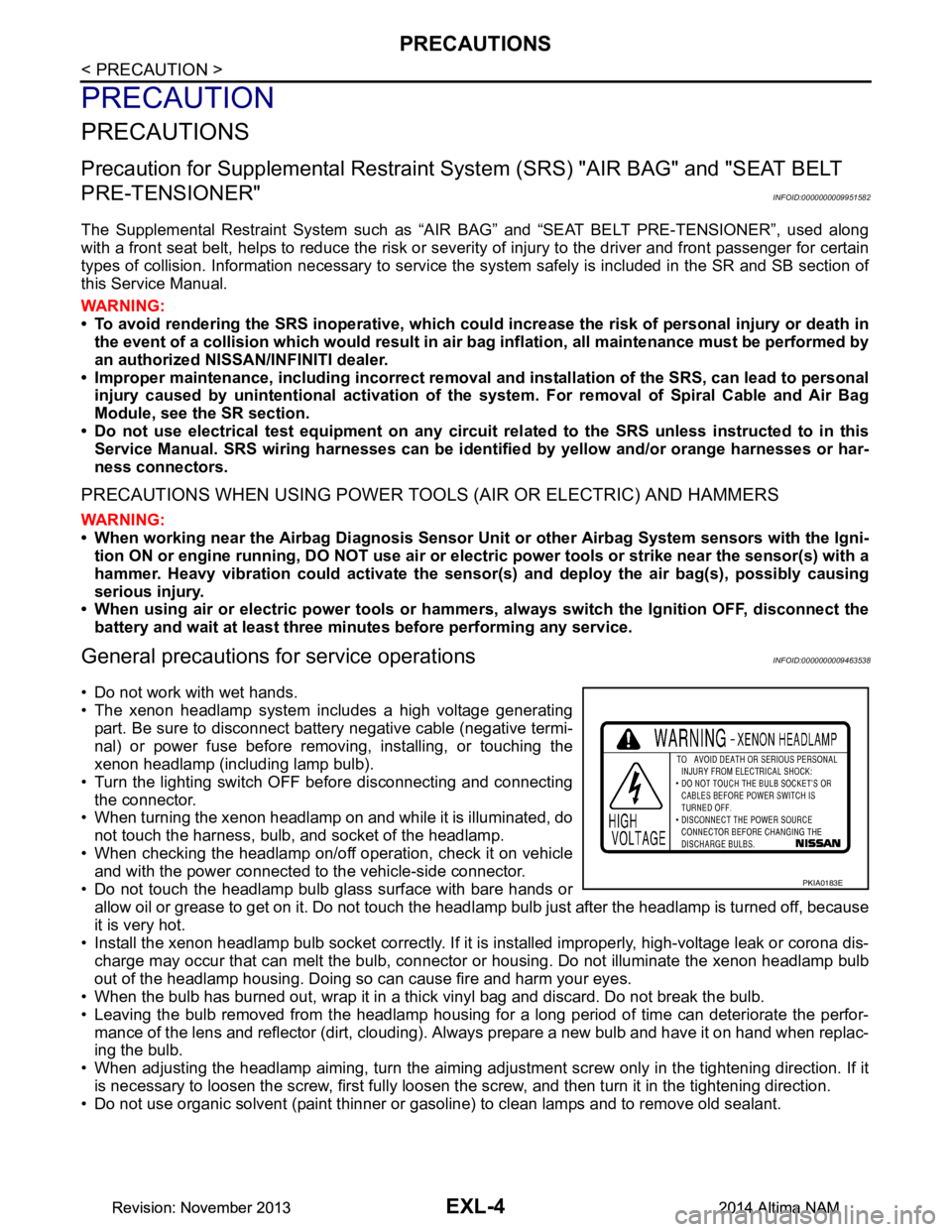
• The xenon headlamp system includes a high voltage generating
part. Be sure to disconnect batte ry negative cable (negative termi-
nal) or power fuse before removing, installing, or touching the
xenon headlamp (including lamp bulb).
• Turn the lighting switch OFF before disconnecting and connecting the connector.
• When turning the xenon headlamp on and while it is illuminated, do
not touch the harness, bulb, and socket of the headlamp.
• When checking the headlamp on/off operation, check it on vehicle and with the power connected to the vehicle-side connector.
• Do not touch the headlamp bulb glass surface with bare hands or allow oil or grease to get on it. Do not touch the headl amp bulb just after the headlamp is turned off, because
it is very hot.
• Install the xenon headlamp bulb socket co rrectly. If it is installed improperly, high-voltage leak or corona dis-
charge may occur that can melt the bulb, connector or housing. Do not illuminate the xenon headlamp bulb
out of the headlamp housing. Doing so can cause fire and harm your eyes.
• When the bulb has burned out, wrap it in a thick vinyl bag and discard. Do not break the bulb.
• Leaving the bulb removed from the headlamp housing for a long period of time can deteriorate the perfor- mance of the lens and reflector (dirt, clouding). Al ways prepare a new bulb and have it on hand when replac-
ing the bulb.
• When adjusting the headlamp aiming, turn the aiming adjus tment screw only in the tightening direction. If it
is necessary to loosen the screw, first fully loosen the screw, and then turn it in the tightening direction.
• Do not use organic solvent (paint thinner or gasoline) to clean lamps and to remove old sealant.
PKIA0183E
Revision: November 20132014 Altima NAMRevision: November 20132014 Altima NAM