check NISSAN TEANA 2014 Workshop Manual
[x] Cancel search | Manufacturer: NISSAN, Model Year: 2014, Model line: TEANA, Model: NISSAN TEANA 2014Pages: 4801, PDF Size: 51.2 MB
Page 127 of 4801
VACUUM LINESBR-31
< REMOVAL AND INSTALLATION >
C
D E
G H
I
J
K L
M A
B
BR
N
O P
VACUUM LINES
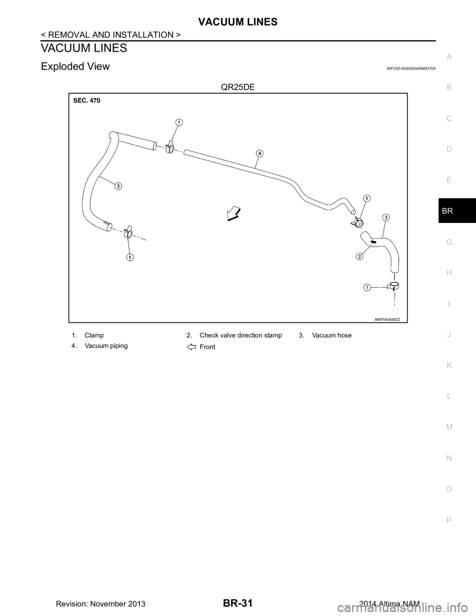
Exploded ViewINFOID:0000000009463709
QR25DE
AWFIA0939ZZ
1. Clamp 2. Check valve direction stamp 3. Vacuum hose
4. Vacuum piping Front
Revision: November 20132014 Altima NAM
Page 128 of 4801
BR-32
< REMOVAL AND INSTALLATION >
VACUUM LINES
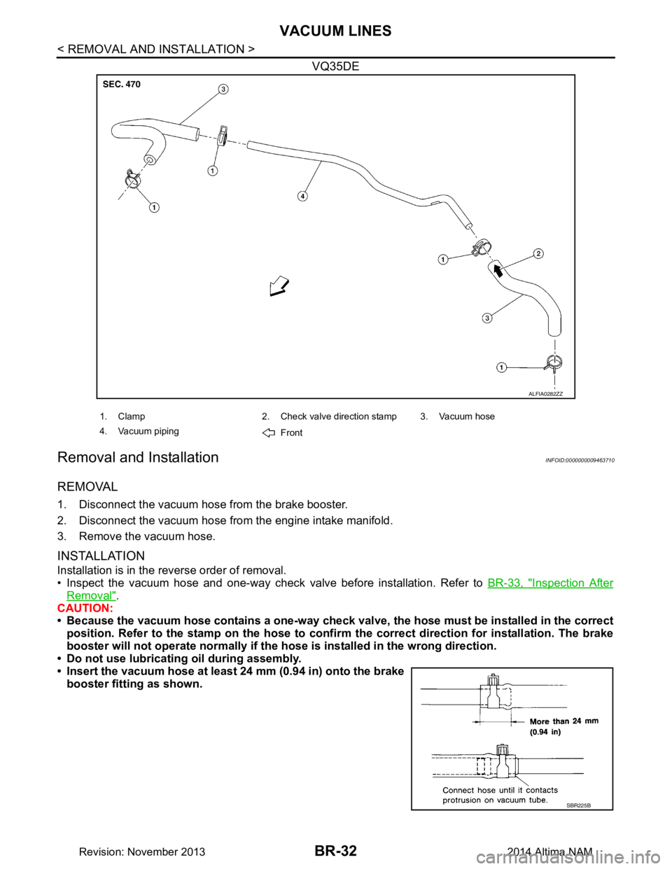
VQ35DE
Removal and InstallationINFOID:0000000009463710
REMOVAL
1. Disconnect the vacuum hose from the brake booster.
2. Disconnect the vacuum hose from the engine intake manifold.
3. Remove the vacuum hose.
INSTALLATION
Installation is in the reverse order of removal.
• Inspect the vacuum hose and one-way check valve before installation. Refer to BR-33, "Inspection After
Removal".
CAUTION:
• Because the vacuum hose contains a one-way check val ve, the hose must be installed in the correct
position. Refer to the stamp on the hose to confi rm the correct direction for installation. The brake
booster will not operate normally if the ho se is installed in the wrong direction.
• Do not use lubricating oil during assembly.
• Insert the vacuum hose at least 24 mm (0.94 in) onto the brake booster fitting as shown.
ALFIA0282ZZ
1. Clamp 2. Check valve direction stamp 3. Vacuum hose
4. Vacuum piping Front
SBR225B
Revision: November 20132014 Altima NAM
Page 129 of 4801
VACUUM LINESBR-33
< REMOVAL AND INSTALLATION >
C
D E
G H
I
J
K L
M A
B
BR
N
O P
Inspection After RemovalINFOID:0000000009463711
VISUAL
Check for correct assembly, damage and deterioration.
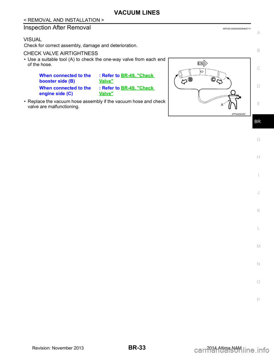
CHECK VALVE AIRTIGHTNESS
• Use a suitable tool (A) to check the one-way valve from each end of the hose.
• Replace the vacuum hose assembly if the vacuum hose and check valve are malfunctioning. When connected to the
booster side (B) : Refer to
BR-49, "Check
Valve"
When connected to the
engine side (C) : Refer to
BR-49, "Check
Valve"
JPFIA0024ZZ
Revision: November 20132014 Altima NAM
Page 131 of 4801

FRONT DISC BRAKEBR-35
< REMOVAL AND INSTALLATION >
C
D E
G H
I
J
K L
M A
B
BR
N
O P
3. Remove upper and lower sliding pin bolts. Refer to BR-36,
"BRAKE CALIPER ASSEMBLY : Exploded View".
NOTE:
Note the pin orientation during removal. The lower sliding pin
contains a bushing.
4. Remove the brake caliper from the torque member. Leaving the brake hose attached, reposition the brake
caliper aside with wire.
CAUTION:
Do not twist or stretch brake hose.
5. Remove the brake pads, shims, and shim covers from the torque member.
6. Remove the brake pad retainers from the torque member. CAUTION:
When removing the brake pad retainers from the torque
member, lift it in the direct ion indicated by the arrow as
shown so that it does not deform.
INSTALLATION
Installation is in the reverse order of removal.
• Apply Molykote AS-880N grease or equivalent betw een the outer brake pad, outer shim cover and outer
shim and between the inner shim and inner brake pad. Inst all outer shim and outer shim cover to outer brake
pad. Install inner shim and inner shim cover to inner brake pad.
CAUTION:
• The inner shim cover (LH) (1) is different than the inner shim
cover (RH) (2). Install the i nner shim covers in the correct
position.
• Replace brake pad shims and covers as a set if any corro-
sion or damage exists.
• Apply Molykote 7439 grease or equivalent between brake pad retainers and brake pad ends. Install brake pad retainers and
brake pads to torque member.
CAUTION:
• Make sure the brake pad retainers are fastened properly to
the torque member.
• Replace brake pad retainers if damage exists.
• Press the piston into the cylinder bore of the caliper using a suitable tool.
• Check brake fluid level and refill as necessary. Refer to BR-8, "Inspection"
.
• Burnish contact surface between brake pads and disc brake rotors. Refer to BR-16, "Brake Burnishing"
.
BRAKE CALIPER ASSEMBLY
ALFIA0300ZZ
SBR556E
ALFIA0359ZZ
Revision: November 20132014 Altima NAM
Page 135 of 4801

REAR DISC BRAKEBR-39
< REMOVAL AND INSTALLATION >
C
D E
G H
I
J
K L
M A
B
BR
N
O P
CAUTION:
Do not twist or stretch the brake hose.
5. Remove the brake pads and shims from the torque member.
6. Remove the brake pad retainers from the torque member. CAUTION:
• When removing the brake pad retainers from the torque
member, lift in the directi on indicated by the arrow as
shown so that it does not deform.
• Replace brake pad retainers if damage exists.
INSTALLATION
Installation is in the reverse order of removal.
• Apply Molykote AS-880N grease or equivalent betw een the outer brake pad, outer shim cover and outer
shim and the inner shim and inner brake pad. Install out er shim, outer shim cover to outer brake pad, and
inner shim, inner shim cover to inner brake pad.
CAUTION:
Replace brake pad shims and covers if damage exists.
• Apply Molykote 7439 grease or equivalent between brake pad retainers and brake pad ends. Install brake pad retainers and brake pads on torque member.
CAUTION:
• Make sure the brake pad retainers are fastened properly to the torque member.
• Replace brake pad retainers if damage exists.
• Using a suitable tool, press the piston into the cylinder bore of the caliper.
• Check brake fluid level and refill as necessary. Refer to BR-8, "Inspection"
.
• Burnish contact surface between brake pads and disc brake rotors. Refer to BR-17, "Brake Burnishing"
.
BRAKE CALIPER ASSEMBLY
BRAKE CALIPER ASSEMBLY : Exploded ViewINFOID:0000000009463718
SBR556E
AWFIA0937ZZ
Revision: November 20132014 Altima NAM
Page 139 of 4801
FRONT DISC BRAKEBR-43
< UNIT DISASSEMBLY AND ASSEMBLY >
C
D E
G H
I
J
K L
M A
B
BR
N
O P
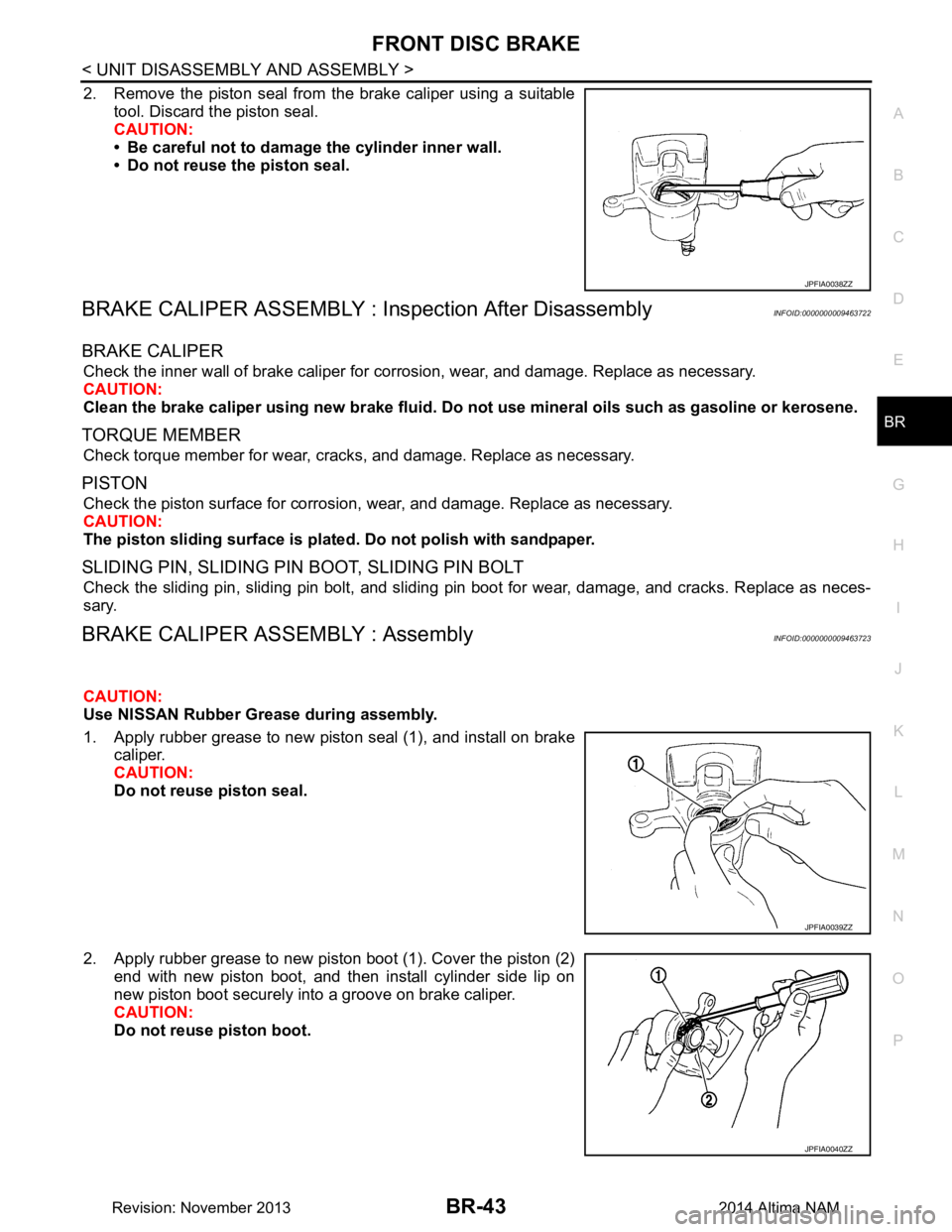
2. Remove the piston seal from the brake caliper using a suitable tool. Discard the piston seal.
CAUTION:
• Be careful not to damage the cylinder inner wall.
• Do not reuse the piston seal.
BRAKE CALIPER ASSEMBLY : In spection After DisassemblyINFOID:0000000009463722
BRAKE CALIPER
Check the inner wall of brake caliper for co rrosion, wear, and damage. Replace as necessary.
CAUTION:
Clean the brake caliper using new br ake fluid. Do not use mineral oils such as gasoline or kerosene.
TORQUE MEMBER
Check torque member for wear, cracks, and damage. Replace as necessary.
PISTON
Check the piston surface for corrosion, wear, and damage. Replace as necessary.
CAUTION:
The piston sliding surface is plated . Do not polish with sandpaper.
SLIDING PIN, SLIDING PIN BOOT, SLIDING PIN BOLT
Check the sliding pin, sliding pin bolt, and sliding pin boot for wear, damage, and cracks. Replace as neces-
sary.
BRAKE CALIPER ASSEMBLY : AssemblyINFOID:0000000009463723
CAUTION:
Use NISSAN Rubber Grease during assembly.
1. Apply rubber grease to new piston seal (1), and install on brake caliper.
CAUTION:
Do not reuse piston seal.
2. Apply rubber grease to new piston boot (1). Cover the piston (2) end with new piston boot, and then install cylinder side lip on
new piston boot securely into a groove on brake caliper.
CAUTION:
Do not reuse piston boot.
JPFIA0038ZZ
JPFIA0039ZZ
JPFIA0040ZZ
Revision: November 20132014 Altima NAM
Page 142 of 4801

BR-46
< UNIT DISASSEMBLY AND ASSEMBLY >
REAR DISC BRAKE
2. Place a wooden block in the brake caliper as shown, and blowair into the union bolt hole to the remove piston and piston boot.
WARNING:
Do not get fingers caught be tween the piston and wooden
block.
3. Remove the piston seal from the brake caliper using a suitable tool. Discard the piston seal.
CAUTION:
• Be careful not to damage the cylinder inner wall.
• Do not reuse the piston seal.
BRAKE CALIPER ASSEMBLY : In spection After DisassemblyINFOID:0000000009463726
BRAKE CALIPER
Check the inner wall of the cylinder for corrosion, wear, and damage. Replace as necessary.
CAUTION:
Clean the brake caliper using new br ake fluid. Do not use mineral oils such as gasoline or kerosene.
TORQUE MEMBER
Check the torque member for wear, cr acks, and damage. Replace as necessary.
PISTON
Check the piston surface for corrosion, wear, and damage. Replace as necessary.
CAUTION:
The piston sliding surface is plated . Do not polish with sandpaper.
SLIDING PIN BOLT, SLIDING PIN BOOT
Check the sliding pin bolt and sliding pin boot fo r wear, damage, and cracks. Replace as necessary.
BRAKE CALIPER ASSEMBLY : AssemblyINFOID:0000000009463727
CAUTION:
Use NISSAN Rubber Grease during assembly.
1. Apply rubber grease to new piston seal (1), and install on brake caliper.
CAUTION:
Do not reuse piston seal.
BRD0041D
JPFIA0038ZZ
JPFIA0039ZZ
Revision: November 20132014 Altima NAM
Page 145 of 4801
SERVICE DATA AND SPECIFICATIONS (SDS)BR-49
< SERVICE DATA AND SPECIFICATIONS (SDS)
C
D E
G H
I
J
K L
M A
B
BR
N
O P
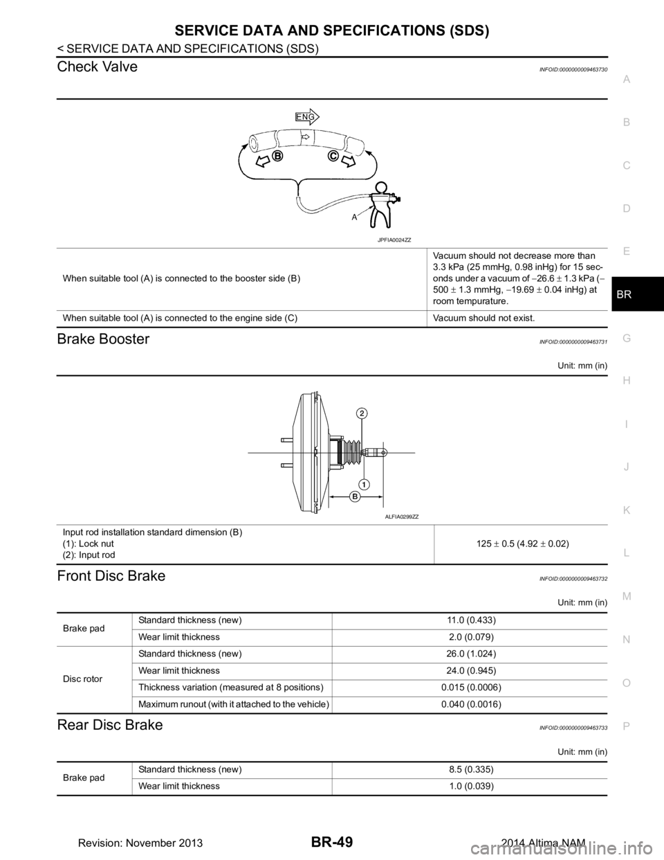
Check ValveINFOID:0000000009463730
Brake BoosterINFOID:0000000009463731
Unit: mm (in)
Front Disc BrakeINFOID:0000000009463732
Unit: mm (in)
Rear Disc BrakeINFOID:0000000009463733
Unit: mm (in)
When suitable tool (A) is connected to the booster side (B) Vacuum should not decrease more than
3.3 kPa (25 mmHg, 0.98 inHg) for 15 sec-
onds under a vacuum of −26.6 ± 1.3 kPa ( −
500 ± 1.3 mmHg, −19.69 ± 0.04 inHg) at
room tempurature.
When suitable tool (A) is connected to the engine side (C) Vacuum should not exist.
JPFIA0024ZZ
Input rod installation standard dimension (B)
(1): Lock nut
(2): Input rod 125
± 0.5 (4.92 ± 0.02)
ALFIA0299ZZ
Brake pad Standard thickness (new) 11.0 (0.433)
Wear limit thickness 2.0 (0.079)
Disc rotor Standard thickness (new) 26.0 (1.024)
Wear limit thickness 24.0 (0.945)
Thickness variation (measured at 8 positions) 0.015 (0.0006)
Maximum runout (with it attached to the vehicle) 0.040 (0.0016)
Brake pad Standard thickness (new) 8.5 (0.335)
Wear limit thickness 1.0 (0.039)
Revision: November 20132014 Altima NAM
Page 148 of 4801

BRC-2
Work Procedure ......................................................62
DTC/CIRCUIT DIAGNOSIS ...................... ...64
C1101, C1102, C1103, C1104 WHEEL SEN-
SOR ................................................................. ...
64
DTC Logic ............................................................ ...64
Diagnosis Procedure ..............................................64
C1105, C1106, C1107, C1108 WHEEL SEN-
SOR ................................................................. ...
68
DTC Logic ............................................................ ...68
Diagnosis Procedure ..............................................68
C1109 POWER AND GROUND SYSTEM .........70
DTC Logic ............................................................ ...70
Diagnosis Procedure ..............................................70
C1110, C1153, C1170 ABS ACTUATOR AND
ELECTRIC UNIT (CONTROL UNIT) .............. ...
72
DTC Logic ............................................................ ...72
Diagnosis Procedure ..............................................72
C1111 PUMP MOTOR .......................................73
DTC Logic ............................................................ ...73
Diagnosis Procedure ..............................................73
C1113, C1145, C1146 YAW RATE/SIDE/DE-
CEL G SENSOR ............................................. ...
75
DTC Logic ............................................................ ...75
Diagnosis Procedure ..............................................75
C1115 ABS SENSOR [ABNORMAL SIGNAL] ...76
DTC Logic ............................................................ ...76
Diagnosis Procedure ..............................................76
C1116 STOP LAMP SWITCH ............................78
DTC Logic ............................................................ ...78
Diagnosis Procedure ..............................................78
C1120, C1122, C1124, C1126 ABS IN VALVE
SYSTEM ............ .............................................. ...
80
DTC Logic ............................................................ ...80
Diagnosis Procedure ..............................................80
C1121, C1123, C1125, C1127 ABS OUT
VALVE SYSTEM ............................................. ...
82
DTC Logic ............................................................ ...82
Diagnosis Procedure ..............................................82
C1130 ENGINE SIGNAL ...................................84
DTC Logic ............................................................ ...84
Diagnosis Procedure ..............................................84
C1140 ACTUATOR RELAY SYSTEM ...............85
DTC Logic ............................................................ ...85
Diagnosis Procedure ..............................................85
C1142 PRESS SENSOR ...................................87
DTC Logic ............................................................ ...87
Diagnosis Procedure ..............................................87
C1143 STEERING ANGLE SENSOR ...............88
DTC Logic ............................................................ ...88
Diagnosis Procedure ...............................................88
C1144 INCOMPLETE STEERING ANGLE
SENSOR ADJUSTMENT ............................... ...
90
DTC Logic ............................................................ ...90
Diagnosis Procedure ...............................................90
C1154 PNP SWITCH .........................................91
Description ........................................................... ...91
DTC Logic ...............................................................91
Diagnosis Procedure ...............................................91
Special Repair Requirement ...................................91
C1155 BR FLUID LEVEL LOW .........................93
DTC Logic ............................................................ ...93
Diagnosis Procedure ...............................................93
Component Inspection ............................................94
C1160 DECEL G SEN SET ...............................95
DTC Logic ............................................................ ...95
Diagnosis Procedure ...............................................95
C1164, C1165, C1166, C1167 CV/SV SYS-
TEM ................................................................. ...
96
DTC Logic ............................................................ ...96
Diagnosis Procedure ...............................................96
C1197 VACUUM SENSOR ............................. ...98
DTC Logic ............................................................ ...98
Diagnosis Procedure ...............................................98
C1198 VACUUM SENSOR ............................. ..100
DTC Logic ............................................................ .100
Diagnosis Procedure .............................................100
C1199 BRAKE BOOSTER ............................. ..102
DTC Logic ............................................................ .102
Diagnosis Procedure .............................................102
C119A VACUUM SENSOR ..............................104
DTC Logic ............................................................ .104
Diagnosis Procedure .............................................104
U1000 CAN COMM CIRCUIT ...........................106
DTC Logic ............................................................ .106
Diagnosis Procedure .............................................106
U1002 SYSTEM COMM (CAN) ........................107
DTC Logic ............................................................ .107
Diagnosis Procedure .............................................107
PARKING BRAKE SWITCH .............................108
Component Function Check ................................ .108
Diagnosis Procedure .............................................108
Component Inspection ..........................................109
VDC OFF SWITCH ...........................................110
Component Function Check ................................ .110
Diagnosis Procedure .............................................110
Component Inspection ..........................................111
Revision: November 20132014 Altima NAMRevision: November 20132014 Altima NAM
Page 149 of 4801

BRC-3
C
D E
G H
I
J
K L
M A
B
BRC
N
O P
ABS WARNING LA MP ................................... ..112
Component Function Check ................................ ..112
Diagnosis Procedure .............................................112
BRAKE WARNING LAMP ............................. ..113
Component Function Check ................................ ..113
Diagnosis Procedure .............................................113
VDC OFF INDICATOR LAMP ..........................114
Description .......................................................... ..114
Component Function Check ..................................114
Diagnosis Procedure .............................................114
SLIP INDICATOR LAMP ..................................115
Component Function Check ................................ ..115
Diagnosis Procedure .............................................115
SYMPTOM DIAGNOSIS ............................116
VDC/TCS/ABS ................................................ ..116
Symptom Table ................................................... ..116
EXCESSIVE ABS FUNCTION OPERATION
FREQUENCY ................................................. ..
117
Diagnosis Procedure ........................................... ..117
UNEXPECTED PEDAL REACTION ................118
Diagnosis Procedure ........................................... ..118
THE BRAKING DISTANCE IS LONG ..............119
Diagnosis Procedure ........................................... ..119
ABS FUNCTION DOES NOT OPERATE .........120
Diagnosis Procedure ........................................... ..120
PEDAL VIBRATION OR ABS OPERATION
SOUND OCCURS .......................................... ..
121
Diagnosis Procedure ........................................... ..121
VEHICLE JERKS DURING VDC/TCS/ABS
CONTROL .......................................................
122
Diagnosis Procedure ........................................... ..122
NORMAL OPERATING CONDITION .............123
Description .............................................................123
REMOVAL AND INSTALLATION .............124
WHEEL SENSOR ............................................124
Exploded View - Front Wheel Sensor .................. ..124
Removal and Installation - Front Wheel Sensor ....124
Exploded View - Rear Wheel Sensor ....................125
Removal and Installation - Rear Wheel Sensor .....125
SENSOR ROTOR ............................................127
Removal and Installation - Front Sensor Rotor .....127
Removal and Installation - Rear Sensor Rotor ......127
ABS ACTUATOR AND ELECTRIC UNIT
(CONTROL UNIT) ...........................................
128
Exploded View ..................................................... ..128
Removal and Installation .......................................128
VDC OFF SWITCH ..........................................130
Removal and Installation .......................................130
YAW RATE/SIDE/DECEL G SENSOR ...........131
Removal and Installation .......................................131
STEERING ANGLE SENSOR .........................132
Exploded View .......................................................132
Removal and Installation .......................................132
Revision: November 20132014 Altima NAMRevision: November 20132014 Altima NAM