torque NISSAN TEANA 2014 Service Manual
[x] Cancel search | Manufacturer: NISSAN, Model Year: 2014, Model line: TEANA, Model: NISSAN TEANA 2014Pages: 4801, PDF Size: 51.2 MB
Page 100 of 4801
BR-4
< PRECAUTION >
PRECAUTIONS
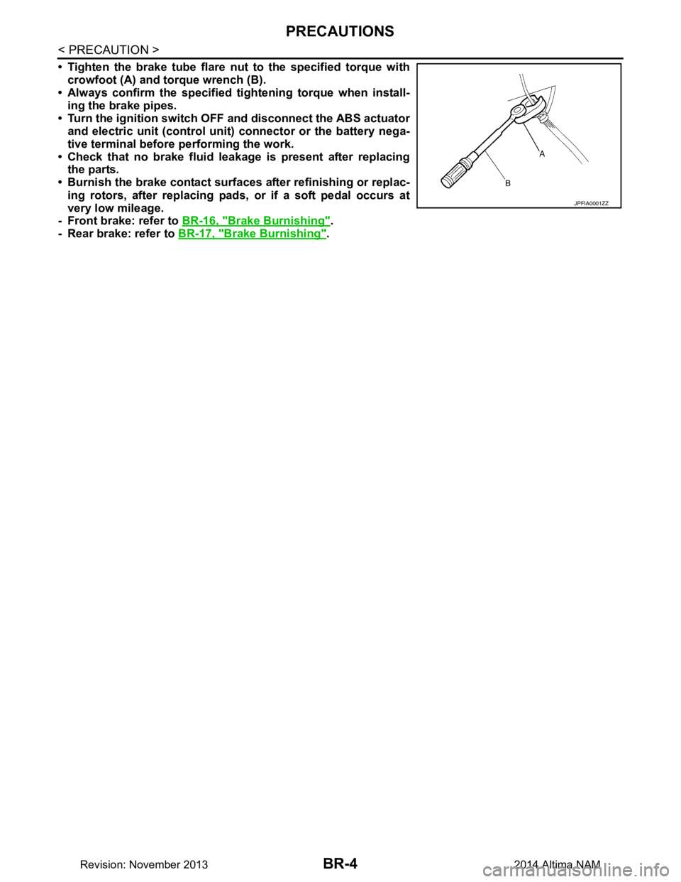
• Tighten the brake tube flare nut to the specified torque with
crowfoot (A) and torque wrench (B).
• Always confirm the specified ti ghtening torque when install-
ing the brake pipes.
• Turn the ignition switch OFF and disconnect the ABS actuator
and electric unit (control unit) connector or the battery nega-
tive terminal before performing the work.
• Check that no brake fluid leakage is present after replacing the parts.
• Burnish the brake contact surf aces after refinishing or replac-
ing rotors, after replacing pads, or if a soft pedal occurs at
very low mileage.
- Front brake: refer to BR-16, "Brake Burnishing"
.
- Rear brake: refer to BR-17, "Brake Burnishing"
.
JPFIA0001ZZ
Revision: November 20132014 Altima NAM
Page 101 of 4801

PREPARATIONBR-5
< PREPARATION >
C
D E
G H
I
J
K L
M A
B
BR
N
O P
PREPARATION
PREPARATION
Special Service ToolINFOID:0000000009463679
The actual shape of the tools may di ffer from those illustrated here.
Commercial Service ToolINFOID:0000000009463680
Tool number
(TechMate No.)
Tool name Description
—
(J-46532)
Brake height tool Measuring brake pedal height
38-PFM92
(—)
Pro-Cut 9.2 Lathe Refinishing rotors
LFIA0227E
ALFIA0092ZZ
Tool name
Description
1. Flare nut crowfoot
2. Torque wrench Removing and installing brake piping
a: 10mm (0.39 in)/12mm (0.47 in)
Power tool Loosening nuts, screws and bolts
NT360
PIIB1407E
Revision: November 20132014 Altima NAM
Page 109 of 4801
BRAKE PEDALBR-13
< PERIODIC MAINTENANCE >
C
D E
G H
I
J
K L
M A
B
BR
N
O P
PERIODIC MAINTENANCE
BRAKE PEDAL
Inspection and AdjustmentINFOID:0000000009463691
ADJUSTMENT
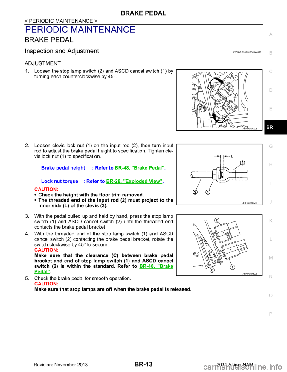
1. Loosen the stop lamp switch (2) and ASCD cancel switch (1) by turning each counterclockwise by 45 °.
2. Loosen clevis lock nut (1) on the input rod (2), then turn input rod to adjust the brake pedal height to specification. Tighten cle-
vis lock nut (1) to specification.
CAUTION:
• Check the height with the floor trim removed.
• The threaded end of the input rod (2) must project to the
inner side (L) of the clevis (3).
3. With the pedal pulled up and held by hand, press the stop lamp switch (1) and ASCD cancel switch (2) until the threaded end
contacts the brake pedal bracket.
4. With the threaded end of the stop lamp switch (1) and ASCD cancel switch (2) contacting the brake pedal bracket, rotate the
switch clockwise by 45 ° to secure.
CAUTION:
Make sure that the clearance (C) between brake pedal
bracket and end of stop lamp switch (1) and ASCD cancel
switch (2) is within the standard. Refer to BR-48, "Brake
Pedal".
5. Check the brake pedal for smooth operation. CAUTION:
Make sure that stop lamps are off when the brake pedal is released.
ALFIA0277ZZ
Brake pedal height : Refer to BR-48, "Brake Pedal".
Lock nut torque : Refer to BR-28, "Exploded View"
.
JPFIA0003ZZ
ALFIA0278ZZ
Revision: November 20132014 Altima NAM
Page 111 of 4801

BRAKE FLUIDBR-15
< PERIODIC MAINTENANCE >
C
D E
G H
I
J
K L
M A
B
BR
N
O P
4. Repeat steps 2 and 3 until all of the air is out of the brake line.
5. Tighten the bleeder valve to the specified torque. Refer to BR-36, "BRAKE CALIPER ASSEMBLY :
Exploded View" (front disc brake) or BR-39, "BRAKE CALIPER ASSEMBLY : Exploded View" (rear disc
brake).
6. Repeat steps 1 to 5, for the remaining brake calipers with master cylinder reservoir tank filled at least half-
way, bleed air from brake hydraulic line bleeder valves in the following order:
Front right brake →Front left brake →Rear right brake →Rear left brake
Revision: November 20132014 Altima NAM
Page 115 of 4801

BRAKE PEDALBR-19
< REMOVAL AND INSTALLATION >
C
D E
G H
I
J
K L
M A
B
BR
N
O P
Installation is in the reverse order of removal.
CAUTION:
Do not reuse the snap pin or clevis pin.
• Adjust the brake pedal height after installing the brake pedal assembly. Refer to BR-13, "Inspection and
Adjustment".
• Tighten the clevis lock nut to the specified torque. Refer to BR-28, "Exploded View"
.
Revision: November 20132014 Altima NAM
Page 118 of 4801
BR-22
< REMOVAL AND INSTALLATION >
BRAKE PIPING
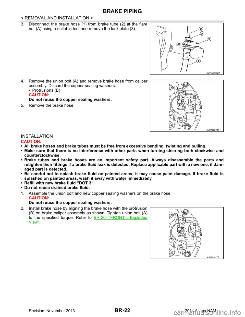
3. Disconnect the brake hose (1) from brake tube (2) at the flarenut (A) using a suitable tool and remove the lock plate (3).
4. Remove the union bolt (A) and remove brake hose from caliper assembly. Discard the copper sealing washers.
• Protrusions (B)
CAUTION:
Do not reuse the copper sealing washers.
5. Remove the brake hose.
INSTALLATION
CAUTION:
• All brake hoses and brake tubes must be free fr om excessive bending, twisting and pulling.
• Make sure that there is no interference with othe r parts when turning steering both clockwise and
counterclockwise.
• Brake tubes and brake hoses are an important safety part. Always disassemble the parts and
retighten their fittings if a brake fluid leak is detect ed. Replace applicable part with a new one, if dam-
aged part is detected.
• Be careful not to splash brake fluid on painted areas; it may cause paint damage. If brake fluid is
splashed on painted areas, wash it away with water immediately.
• Refill with new brake fluid “DOT 3”.
• Do not reuse drained brake fluid.
1. Assemble the union bolt and new copper sealing washers on the brake hose. CAUTION:
Do not reuse the copper sealing washers.
2. Install brake hose by aligning the brake hose with the protrusion (B) on brake caliper assembly as shown. Tighten union bolt (A)
to the specified torque. Refer to BR-20, "FRONT : Exploded
View".
AWFIA0933ZZ
ALFIA0287ZZ
ALFIA0287ZZ
Revision: November 20132014 Altima NAM
Page 119 of 4801
BRAKE PIPINGBR-23
< REMOVAL AND INSTALLATION >
C
D E
G H
I
J
K L
M A
B
BR
N
O P
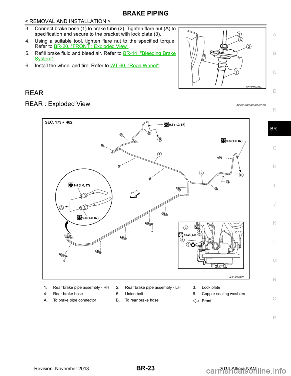
3. Connect brake hose (1) to brake tube (2). Tighten flare nut (A) to specification and secure to the bracket with lock plate (3).
4. Using a suitable tool, tighten flare nut to the specified torque. Refer to BR-20, "FRONT : Exploded View"
.
5. Refill brake fluid and bleed air. Refer to BR-14, "Bleeding Brake
System".
6. Install the wheel and tire. Refer to WT-60, "Road Wheel"
.
REAR
REAR : Exploded ViewINFOID:0000000009463701
AWFIA0933ZZ
1. Rear brake pipe assembly - RH 2. Rear brake pipe assembly - LH 3. Lock plate
4. Rear brake hose 5. Union bolt 6. Copper sealing washers
A. To brake pipe connector B. To rear brake hose Front
ALFIA0317ZZ
Revision: November 20132014 Altima NAM
Page 121 of 4801
BRAKE PIPINGBR-25
< REMOVAL AND INSTALLATION >
C
D E
G H
I
J
K L
M A
B
BR
N
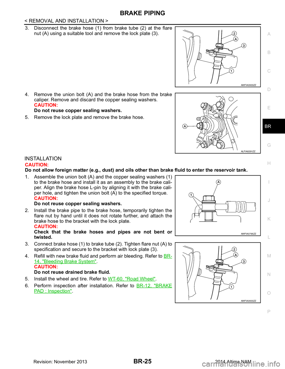
O P
3. Disconnect the brake hose (1) from brake tube (2) at the flare nut (A) using a suitable tool and remove the lock plate (3).
4. Remove the union bolt (A) and the brake hose from the brake caliper. Remove and discard the copper sealing washers.
CAUTION:
Do not reuse copper sealing washers.
5. Remove the lock plate and remove the brake hose.
INSTALLATION
CAUTION:
Do not allow foreign matte r (e.g., dust) and oils other than brake fluid to enter the reservoir tank.
1. Assemble the union bolt (A) and the copper sealing washers (1) to the brake hose and install it as an assembly to the brake cali-
per. Align the brake hose L-pin by aligning it with the brake cali-
per hole, and tighten the union bolt (A) to the specified torque.
CAUTION:
Do not reuse copper sealing washers.
2. Install the brake pipe to the brake hose, temporarily tighten the flare nut by hand until it does not rotate further, and attach the
brake hose to the bracket with the lock plate.
CAUTION:
Check that the brake hoses and pipes are not bent or
twisted.
3. Connect brake hose (1) to brake tube (2). Tighten flare nut (A) to specification and secure to the bracket with lock plate (3).
4. Refill with new brake fluid and perform air bleeding. Refer to BR-
14, "Bleeding Brake System".
CAUTION:
Do not reuse drained brake fluid.
5. Install the wheel and tire. Refer to WT-60, "Road Wheel"
.
6. Perform inspection after installation. Refer to BR-12, "BRAKE
PAD : Inspection".
AWFIA0933ZZ
ALFIA0291ZZ
AWFIA0795ZZ
AWFIA0933ZZ
Revision: November 20132014 Altima NAM
Page 123 of 4801
BRAKE MASTER CYLINDERBR-27
< REMOVAL AND INSTALLATION >
C
D E
G H
I
J
K L
M A
B
BR
N
O P
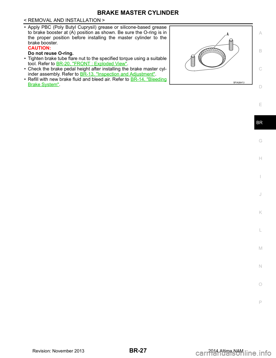
• Apply PBC (Poly Butyl Cuprysil) grease or silicone-based grease to brake booster at (A) position as shown. Be sure the O-ring is in
the proper position before installing the master cylinder to the
brake booster.
CAUTION:
Do not reuse O-ring.
• Tighten brake tube flare nut to the specified torque using a suitable tool. Refer to BR-20, "FRONT : Exploded View"
.
• Check the brake pedal height after installing the brake master cyl-
inder assembly. Refer to BR-13, "Inspection and Adjustment"
.
• Refill with new brake fluid and bleed air. Refer to BR-14, "Bleeding
Brake System".SFIA2847J
Revision: November 20132014 Altima NAM
Page 130 of 4801
BR-34
< REMOVAL AND INSTALLATION >
FRONT DISC BRAKE
FRONT DISC BRAKE
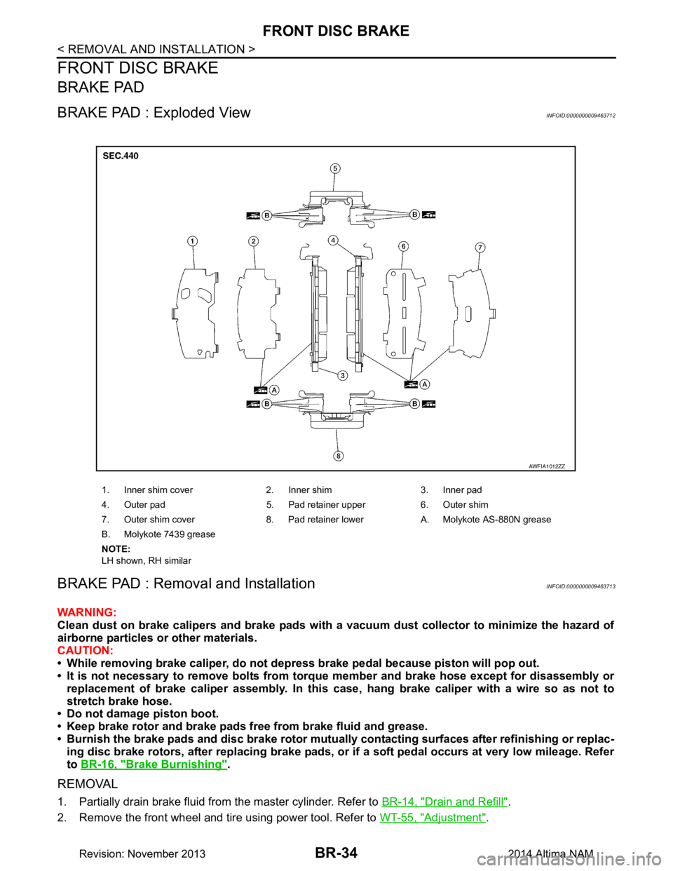
BRAKE PAD
BRAKE PAD : Exploded ViewINFOID:0000000009463712
BRAKE PAD : Removal and InstallationINFOID:0000000009463713
WARNING:
Clean dust on brake calipers and brake pads with a vacuum dust collector to minimize the hazard of
airborne particles or other materials.
CAUTION:
• While removing brake caliper, do not depr ess brake pedal because piston will pop out.
• It is not necessary to remove bolts from torque member and brake hose except for disassembly or
replacement of brake caliper assembly. In this case, hang brake caliper with a wire so as not to
stretch brake hose.
• Do not damage piston boot.
• Keep brake rotor and brake pads free from brake fluid and grease.
• Burnish the brake pads and disc brake rotor mutual ly contacting surfaces after refinishing or replac-
ing disc brake rotors, after replacing brake pads, or if a soft pedal occurs at very low mileage. Refer
to BR-16, "Brake Burnishing"
.
REMOVAL
1. Partially drain brake fluid from the master cylinder. Refer to BR-14, "Drain and Refill".
2. Remove the front wheel and tire using power tool. Refer to WT-55, "Adjustment"
.
1. Inner shim cover 2. Inner shim 3. Inner pad
4. Outer pad 5. Pad retainer upper 6. Outer shim
7. Outer shim cover 8. Pad retainer lower A. Molykote AS-880N grease
B. Molykote 7439 grease
NOTE:
LH shown, RH similar
AWFIA1012ZZ
Revision: November 20132014 Altima NAM