sensor NISSAN TEANA 2014 Service Manual
[x] Cancel search | Manufacturer: NISSAN, Model Year: 2014, Model line: TEANA, Model: NISSAN TEANA 2014Pages: 4801, PDF Size: 51.2 MB
Page 2516 of 4801
FRONT STABILIZERFSU-15
< REMOVAL AND INSTALLATION >
C
D
F
G H
I
J
K L
M A
B
FSU
N
O P
6. Position the steering gear aside. Refer to ST-36, "Exploded View".
• Disconnect the steering gear from steering column.
• Remove the steering gear support bracket on the right side.
• Remove the steering gear bolts.
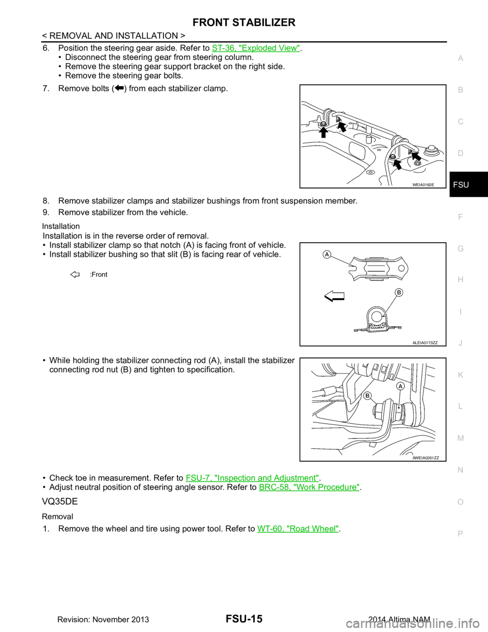
7. Remove bolts ( ) from each stabilizer clamp.
8. Remove stabilizer clamps and stabilizer bushings from front suspension member.
9. Remove stabilizer from the vehicle.
Installation
Installation is in the reverse order of removal.
• Install stabilizer clamp so that notch (A) is facing front of vehicle.
• Install stabilizer bushing so that slit (B) is facing rear of vehicle.
• While holding the stabilizer connecting rod (A), install the stabilizer connecting rod nut (B) and ti ghten to specification.
• Check toe in measurement. Refer to FSU-7, "Inspection and Adjustment"
.
• Adjust neutral position of steering angle sensor. Refer to BRC-58, "Work Procedure"
.
VQ35DE
Removal
1. Remove the wheel and tire using power tool. Refer to WT-60, "Road Wheel".
WEIA0182E
:Front
ALEIA0173ZZ
AWEIA0261ZZ
Revision: November 20132014 Altima NAM
Page 2517 of 4801
FSU-16
< REMOVAL AND INSTALLATION >
FRONT STABILIZER
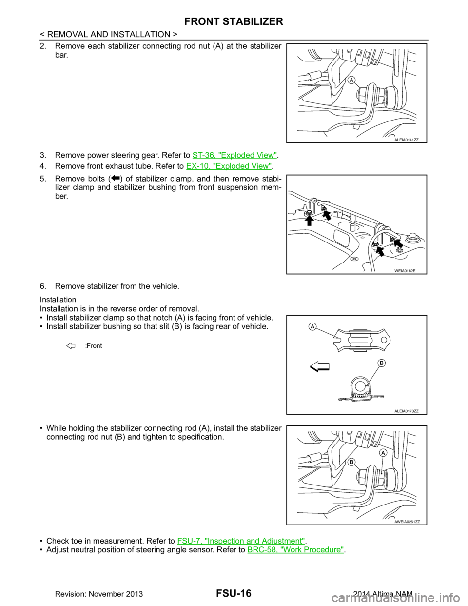
2. Remove each stabilizer connecting rod nut (A) at the stabilizerbar.
3. Remove power steering gear. Refer to ST-36, "Exploded View"
.
4. Remove front exhaust tube. Refer to EX-10, "Exploded View"
.
5. Remove bolts ( ) of stabilizer clamp, and then remove stabi- lizer clamp and stabilizer bushing from front suspension mem-
ber.
6. Remove stabilizer from the vehicle.
Installation
Installation is in the reverse order of removal.
• Install stabilizer clamp so that not ch (A) is facing front of vehicle.
• Install stabilizer bushing so that slit (B) is facing rear of vehicle.
• While holding the stabilizer connecting rod (A), install the stabilizer connecting rod nut (B) and tighten to specification.
• Check toe in measurement. Refer to FSU-7, "Inspection and Adjustment"
.
• Adjust neutral position of steering angle sensor. Refer to BRC-58, "Work Procedure"
.
ALEIA0141ZZ
WEIA0182E
:Front
ALEIA0173ZZ
AWEIA0261ZZ
Revision: November 20132014 Altima NAM
Page 2519 of 4801
FSU-18
< REMOVAL AND INSTALLATION >
STEERING KNUCKLE
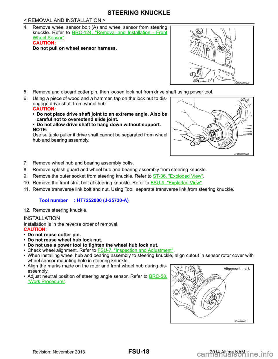
4. Remove wheel sensor bolt (A) and wheel sensor from steeringknuckle. Refer to BRC-124, "Removal and Installation - Front
Wheel Sensor".
CAUTION:
Do not pull on wheel sensor harness.
5. Remove and discard cotter pin, then loosen lock nut from drive shaft using power tool.
6. Using a piece of wood and a hammer, tap on the lock nut to dis- engage drive shaft from wheel hub.
CAUTION:
• Do not place drive shaft joint to an extreme angle. Also be
careful not to over extend slide joint.
• Do not allow drive shaft to hang down without support.
NOTE:
Use suitable puller if drive shaft cannot be separated from wheel
hub and bearing assembly.
7. Remove wheel hub and bearing assembly bolts.
8. Remove splash guard and wheel hub and bearing assembly from steering knuckle.
9. Remove the outer socket from steering knuckle. Refer to ST-36, "Exploded View"
.
10. Remove the front strut bolt at steering knuckle. Refer to FSU-9, "Exploded View"
.
11. Remove transverse link bolt and nut. Using Tool, separate transverse link from steering knuckle.
12. Remove steering knuckle.
INSTALLATION
Installation is in the reverse order of removal.
CAUTION:
• Do not reuse cotter pin.
• Do not reuse wheel hub lock nut.
• Do not use a power tool to tighten the wheel hub lock nut.
• Check wheel alignment. Refer to FSU-7, "Inspection and Adjustment"
.
• When installing wheel hub and bearing assembly to steering knuckle, align cutout in sensor rotor cover with
wheel sensor mounting hole in steering knuckle.
• Align the marks made on the rotor and front wheel hub during dis- assembly.
• Adjust neutral position of steering angle sensor. Refer to BRC-58,
"Work Procedure".
ALDIA0287ZZ
JPDIG0070ZZ
Tool number : HT7252000 (J-25730-A)
SDIA1480E
Revision: November 20132014 Altima NAM
Page 2521 of 4801
FSU-20
< UNIT REMOVAL AND INSTALLATION >
FRONT SUSPENSION ASSEMBLY
Removal and Installation
INFOID:0000000009460637
QR25DE ENGINE
Removal
1. Remove front wheel and tire using power tool. Refer to WT-55, "Adjustment".
2. Remove each brake caliper using power tool, leaving brake caliper hydraulic hose attached. Position each brake caliper aside with wire. Refer to BR-36, "BRAKE CALIPER ASSEMBLY : Exploded View"
.
CAUTION:
• Do not depress brake pedal while brake caliper is removed.
• Do not twist or stretch the brake hose.
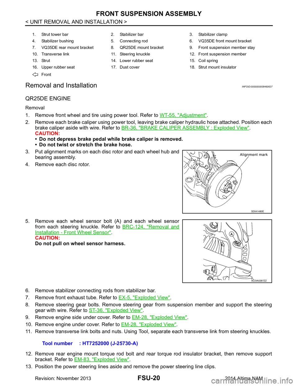
3. Put alignment marks on each disc rotor and each wheel hub and bearing assembly.
4. Remove each disc rotor.
5. Remove each wheel sensor bolt (A) and each wheel sensor from each steering knuckle. Refer to BRC-124, "Removal and
Installation - Front Wheel Sensor".
CAUTION:
Do not pull on wheel sensor harness.
6. Remove stabilizer connecting rods from stabilizer bar.
7. Remove front exhaust tube. Refer to EX-5, "Exploded View"
.
8. Remove steering gear bolts. Remove steering gear from suspension member and support the steering gear with wire. Refer to ST-36, "Exploded View"
.
9. Remove engine side under cover. Refer to EM-28, "Exploded View"
.
10. Remove engine under cover. Refer to EM-28, "Exploded View"
.
11. Remove transverse link bolts and nuts. Using Tool, separate each transverse link from steering knuckles.
12. Remove rear engine mount torque rod bolt and rear torque rod insulator bracket, then remove support bracket. Refer to EM-83, "Exploded View"
.
13. Position the power steering lines aside and remove the power steering line clips.
1. Strut tower bar 2. Stabilizer bar 3. Stabilizer clamp
4. Stabilizer bushing 5. Connecting rod 6. VQ35DE front mount bracket
7. VQ35DE rear mount bracket 8. QR25DE mount bracket 9. Front suspension member stay
10. Transverse link 11. Steering knuckle 12. Front suspension member
13. Strut 14. Lower rubber seat 15. Coil spring
16. Upper rubber seat 17. Dust cover 18. Strut mount insulator
Front
SDIA1480E
ALDIA0287ZZ
Tool number : HT7252000 (J-25730-A)
Revision: November 20132014 Altima NAM
Page 2522 of 4801
FRONT SUSPENSION ASSEMBLYFSU-21
< UNIT REMOVAL AND INSTALLATION >
C
D
F
G H
I
J
K L
M A
B
FSU
N
O P
14. Set Tool under suspension member, and remove suspension member bolts. Slowly lower Tool to remove suspension member from vehicle
15. If replacing suspension member, remove the following components from the suspension member. • transverse links.
• stabilizer bar.
• front suspension member stays.
Installation
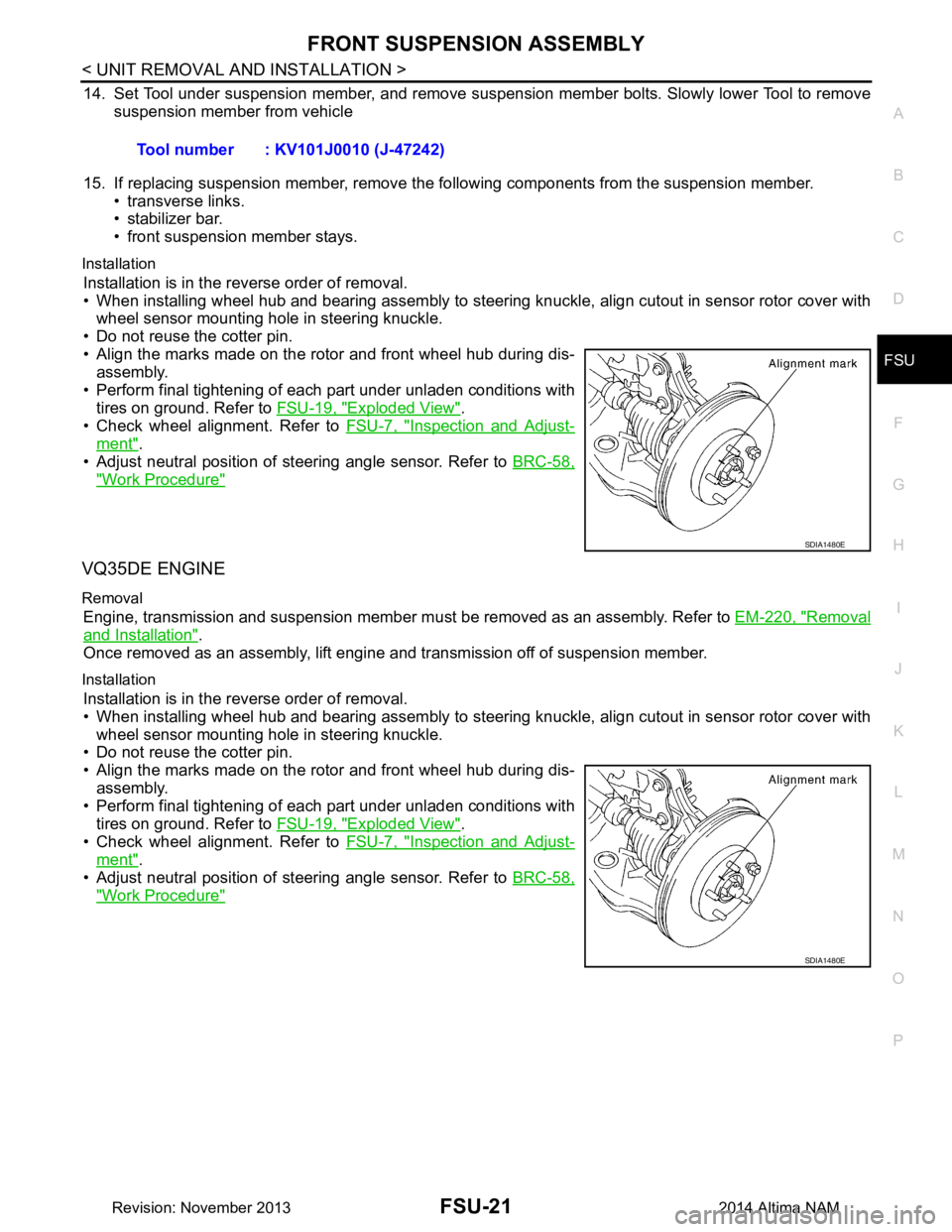
Installation is in the reverse order of removal.
• When installing wheel hub and bearing assembly to steering knuckle, align cutout in sensor rotor cover with wheel sensor mounting hole in steering knuckle.
• Do not reuse the cotter pin.
• Align the marks made on the rotor and front wheel hub during dis- assembly.
• Perform final tightening of each part under unladen conditions with tires on ground. Refer to FSU-19, "Exploded View"
.
• Check wheel alignment. Refer to FSU-7, "Inspection and Adjust-
ment".
• Adjust neutral position of steering angle sensor. Refer to BRC-58,
"Work Procedure"
VQ35DE ENGINE
Removal
Engine, transmission and suspension member must be removed as an assembly. Refer to EM-220, "Removal
and Installation".
Once removed as an assembly, lift engine and transmission off of suspension member.
Installation
Installation is in the reverse order of removal.
• When installing wheel hub and bearing assembly to steering knuckle, align cutout in sensor rotor cover with
wheel sensor mounting hole in steering knuckle.
• Do not reuse the cotter pin.
• Align the marks made on the rotor and front wheel hub during dis-
assembly.
• Perform final tightening of each part under unladen conditions with tires on ground. Refer to FSU-19, "Exploded View"
.
• Check wheel alignment. Refer to FSU-7, "Inspection and Adjust-
ment".
• Adjust neutral position of steering angle sensor. Refer to BRC-58,
"Work Procedure"
Tool number : KV101J0010 (J-47242)
SDIA1480E
SDIA1480E
Revision: November 20132014 Altima NAM
Page 2541 of 4801

ABBREVIATIONSGI-13
< HOW TO USE THIS MANUAL >
C
D E
F
G H
I
J
K L
M B
GI
N
O PABBREVIATIONS
Abbreviation ListINFOID:0000000009462979
The following ABBREVIATIONS are used:
A
B
C
D
ABBREVIATION DESCRIPTION A/C Air conditioner
A/C Air conditioning
A/F sensor Air fuel ratio sensor A/T Automatic transaxle/transmission
ABS Anti-lock braking system
ACCS Advance climate control system ACL Air cleaner
AP Accelerator pedal
APP Accelerator pedal position AV Audio visual
AVM Around view monitor
AWD All wheel drive
ABBREVIATION DESCRIPTION BARO Barometric pressureBCI Backup collision intervention
BCM Body control module
BLSD Brake limited slip differential BPP Brake pedal positionBSI Blind spot intervention
BSW Blind spot warning
ABBREVIATION DESCRIPTION CKP Crankshaft positionCL Closed loop
CMP Camshaft position CPP Clutch pedal positionCTP Closed throttle position
CVT Continuously variable transaxle/transmission
ABBREVIATION DESCRIPTION D
1Drive range first gear
D
2Drive range second gear
D
3Drive range third gear
D
4Drive range fourth gear
DCA Distance control assist
DDS Downhill drive support DFI Direct fuel injection system
DLC Data link connector
DTC Diagnostic trouble code
Revision: November 20132014 Altima NAMRevision: November 20132014 Altima NAM
Page 2542 of 4801

GI-14
< HOW TO USE THIS MANUAL >
ABBREVIATIONS
E
F
G
H
ABBREVIATION DESCRIPTION E/T Exhaust temperature
EBD Electric brake force distribution EC Engine control
ECL Engine coolant level
ECM Engine control module ECT Engine coolant temperature
ECV Electrical control valve
EEPROM Electrically erasable pr ogrammable read only memory
EFT Engine fuel temperature
EGR Exhaust gas recirculation
EGRT Exhaust gas recirculation temperature EGT Exhaust gas temperature
EOP Engine oil pressure EP Exhaust pressure
EPR Exhaust pressure regulator EPS Electronically cont rolled power steering
ESP Electronic stability program system
EVAP canister Evaporative emission canister EVSE Electric vehicle supply equipmentEXC Exhaust control
ABBREVIATION DESCRIPTION FC Fan control
FCW Forward collision warning FIC Fuel injector controlFP Fuel pump
FR Front
FRP Fuel rail pressure
FRT Fuel rail temperatureFTP Fuel tank pressure FTT Fuel tank temperature
ABBREVIATION DESCRIPTION GND GroundGPS Global positioning systemGST Generic scan tool
ABBREVIATION DESCRIPTION HBMC Hydraulic body-motion control systemHDD Hard disk drive
HO2S Heated oxygen sensor HOC Heated oxidation catalyst
HPCM Hybrid power train control module
Revision: November 20132014 Altima NAMRevision: November 20132014 Altima NAM
Page 2543 of 4801

ABBREVIATIONSGI-15
< HOW TO USE THIS MANUAL >
C
D E
F
G H
I
J
K L
M B
GI
N
O P
I
K
L
M
N
O
ABBREVIATION DESCRIPTION I/M Inspection and maintenanceIA Intake air
IAC Idle air control IAT Intake air temperature
IBA Intelligent brake assist IC Ignition control
ICC Intelligent cruise control
ICM Ignition control module
IPDM E/R Intelligent power distribution module engine room ISC Idle speed controlISS Input shaft speed ITS Information technology suite
ABBREVIATION DESCRIPTION KS Knock sensor
ABBREVIATION DESCRIPTION LBC Li-ion battery controller
LCD Liquid crystal display
LCU Local control unit LDP Lane departure prevention
LDW Lane departure warning LED Light emitting diode LH Left-hand
LIN Local interconnect network
ABBREVIATION DESCRIPTION M/T Manual transaxle/transmission
MAF Mass airflow
MAP Manifold absolute pressure
MDU Multi display unit MI Malfunction indicator
MIL Malfunction indicator lamp
MOD Moving object detection
ABBREVIATION DESCRIPTION NOX Nitrogen oxides
ABBREVIATION DESCRIPTION O2 Oxygen
O2S Oxygen sensor
OBD On board diagnostic OC Oxidation catalytic converter
OD Overdrive
Revision: November 20132014 Altima NAMRevision: November 20132014 Altima NAM
Page 2545 of 4801

ABBREVIATIONSGI-17
< HOW TO USE THIS MANUAL >
C
D E
F
G H
I
J
K L
M B
GI
N
O P
W
1
2
3
4
5
6
VIN Vehicle identification number
VSS Vehicle speed sensor
ABBREVIATION DESCRIPTION WOT Wide open throttle
ABBREVIATION DESCRIPTION 1
11st range first gear
1
21st range second gear
1GR First gear
ABBREVIATION DESCRIPTION 2
12nd range first gear
2
22nd range second gear
2GR Second gear
2WD 2-wheel drive
ABBREVIATION DESCRIPTION 3GR Third gear
ABBREVIATION DESCRIPTION 4GR Fourth gear
4WAS Four wheel active steer 4WD Four wheel drive
ABBREVIATION DESCRIPTION 5GR Fifth gear
ABBREVIATION DESCRIPTION 6GR Sixth gear
ABBREVIATION DESCRIPTION
Revision: November 20132014 Altima NAMRevision: November 20132014 Altima NAM
Page 2554 of 4801
GI-26
< PRECAUTION >
PRECAUTIONS
PRECAUTION
PRECAUTIONS
DescriptionINFOID:0000000009462991
Observe the following precautions to ensure safe and proper servicing. These precautions are not
described in each individual section.
Precaution for Supplemental Restraint Syst em (SRS) "AIR BAG" and "SEAT BELT
PRE-TENSIONER"
INFOID:0000000009462992
The Supplemental Restraint System such as “A IR BAG” and “SEAT BELT PRE-TENSIONER”, used along
with a front seat belt, helps to reduce the risk or severi ty of injury to the driver and front passenger for certain
types of collision. Information necessary to service the system safely is included in the SR and SB section of
this Service Manual.
WARNING:
• To avoid rendering the SRS inopera tive, which could increase the risk of personal injury or death in
the event of a collision which would result in air bag inflation, all maintenance must be performed by
an authorized NISS AN/INFINITI dealer.
• Improper maintenance, including in correct removal and installation of the SRS, can lead to personal
injury caused by unintent ional activation of the system. For re moval of Spiral Cable and Air Bag
Module, see the SR section.
• Do not use electrical test equipmen t on any circuit related to the SRS unless instructed to in this
Service Manual. SRS wiring harn esses can be identified by yellow and/or orange harnesses or har-
ness connectors.
PRECAUTIONS WHEN USING POWER TOOLS (AIR OR ELECTRIC) AND HAMMERS
WARNING:
• When working near the Airbag Diagnosis Sensor Unit or other Airbag System sensors with the Igni-
tion ON or engine running, DO NOT use air or electri c power tools or strike near the sensor(s) with a
hammer. Heavy vibration could activate the sensor( s) and deploy the air bag(s), possibly causing
serious injury.
• When using air or electric power tools or hammers , always switch the Ignition OFF, disconnect the
battery and wait at least 3 minutes before performing any service.
Precautions For Xeno n Headlamp ServiceINFOID:0000000009462993
WARNING:
Comply with the following warnings to prevent any serious accident.
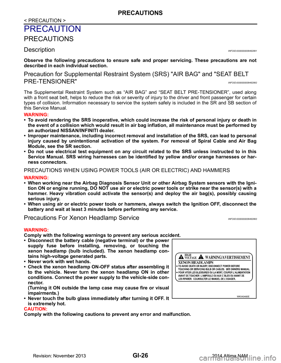
• Disconnect the battery cable (n egative terminal) or the power
supply fuse before in stalling, removing, or touching the
xenon headlamp (bulb included) . The xenon headlamp con-
tains high-voltage generated parts.
• Never work with wet hands.
• Check the xenon headlamp ON-OFF status after assembling it to the vehicle. Never turn the xenon headlamp ON in other
conditions. Connect the power supply to the vehicle-side con-
nector.
(Turning it ON outside the la mp case may cause fire or visual
impairments.)
• Never touch the bulb glass immediately after turning it OFF. It is extremely hot.
CAUTION:
Comply with the following cautions to prevent any error and malfunction.
WKIA0460E
Revision: November 20132014 Altima NAMRevision: November 20132014 Altima NAM