high NISSAN TEANA 2014 Service Manual
[x] Cancel search | Manufacturer: NISSAN, Model Year: 2014, Model line: TEANA, Model: NISSAN TEANA 2014Pages: 4801, PDF Size: 51.2 MB
Page 48 of 4801

BCS
BCM (BODY CONTROL MODULE)BCS-33
< ECU DIAGNOSIS INFORMATION > [BCM]
C
D E
F
G H
I
J
K L
B
A
O P
N
FR WASHER SW
Front washer switch OFF Off
Front washer switch ON On
FR WIPER LOW Front wiper switch OFF Off
Front wiper switch LO On
FR WIPER HI Front wiper switch OFF Off
Front wiper switch HI On
FR WIPER INT Front wiper switch OFF Off
Front wiper switch INT On
FR WIPER STOP Any position other than front wiper stop position Off
Front wiper stop position On
HAZARD SW When hazard switch is not pressed Off
When hazard switch is pressed On
HEAD LAMP SW 1 Headlamp switch OFF Off
Headlamp switch 1st On
HEAD LAMP SW 2 Headlamp switch OFF Off
Headlamp switch 1st On
HI BEAM SW High beam switch OFF Off
High beam switch HI On
ID AUTHENT CANCEL TIMER When I-Key authentication is OFF. STOP
ID OK FLAG Ignition switch ACC or ON Reset
Ignition switch OFF Set
ID REGST FL1 ID registration of front left tire incomplete YET
ID registration of front left tire complete DONE
ID REGST FR1 ID registration of front right tire incomplete YET
ID registration of front right tire complete DONE
ID REGST RL1 ID registration of rear left tire incomplete YET
ID registration of rear left tire complete DONE
ID REGST RR1 ID registration of rear
right tire incomplete YET
ID registration of rear right tire complete DONE
IGN RLY1 F/B Ignition switch OFF or ACC Off
Ignition switch ON On
INT VOLUME Wiper intermittent dial is in a dial position 1 - 7 1 - 7
I-KEY OK FLAG I-Key OFF Key OFF
I-Key ON Key ON
KEY CYL LK-SW Door key cylinder LOCK position Off
Door key cylinder other than LOCK position On
KEY CYL UN-SW Door key cylinder UNLOCK position Off
Door key cylinder other than UNLOCK position On
OPTI SEN (DTCT) Bright outside of the vehicle Close to 5V
Dark outside of the vehicle Close to 0V
OPTI SEN (FILT) Bright outside of the vehicle Close to 5V
Dark outside of the vehicle Close to 0V
PA S S I N G S W Other than lighting switch PASS Off
Lighting switch PASS On
Monitor Item Condition Value/Status
Revision: November 20132014 Altima NAMRevision: November 20132014 Altima NAM
Page 54 of 4801

BCS
BCM (BODY CONTROL MODULE)BCS-39
< ECU DIAGNOSIS INFORMATION > [BCM]
C
D E
F
G H
I
J
K L
B
A
O P
N30
(P) Ground Driver door lock sta-
tus Input Front door LH LOCK status
11 . 8 V
UNLOCK status 0V
32
(Y) Ground
Rear window defog-
ger ON signal Input
Rear window de-
fogger switch OFF 5V
ON 0V
33
(G) Ground Trunk lid opener can-
cel switch InputTrunk lid opener
cancel switch CANCEL
1.1V
ON 0V
34
(BG) Ground Unlock switch signal Input Door lock/unlock
switch Unlock Battery voltage
Lock 0V
36
(Y) Ground Hazard switch Input Hazard switch Pressed 0V
Not pressed
1.1V
39
(L) Ground Shift N/P Input Selector lever P or N position Battery voltage
Except P and N positions 0V
48
(BR) Ground
High side start switch
LED OutputPush-button igni-
tion switch illumi-
nation ON 5.5V
OFF 0V
52
(G) Ground Audio dongle
Input/
Output Push-button ignition switch OFF 5V
54
(P) Ground
Power window link/
communication Input/
Output Push-button igni-
tion switch ON
10.2V
OFF or ACC 0V
59
(P) Ground CAN low
Input/
Output ——
Te r m i n a l N o .
(Wire color) Description
Condition Va l u e
(Approx.)
Signal name Input/
Output
(+) (-)
JPMIA0011GB
JPMIA0012GB
JPMIA0012GB
JPMIA0013GB
Revision: November 20132014 Altima NAMRevision: November 20132014 Altima NAM
Page 55 of 4801

BCS-40
< ECU DIAGNOSIS INFORMATION >[BCM]
BCM (BODY CONTROL MODULE)
60
(L) Ground CAN high Input/
Output ——
61
(Y) Ground Rear defogger relay
output OutputRear window de-
fogger Active Battery voltage
Not activated 0V
62
(BR) Ground Starter relay output Output
Push-button igni-
tion switch ON When selector lever is in P
or N position and the brake
is depressed Battery voltage
When selector lever is in P
or N position and the brake
is not depressed 0V
64
(W) Ground Buzzer output Output Outside warning
buzzer Sounding 0V
Not sounding Battery voltage
66
(R) Ground Blower fan relay out-
put OutputPush-button igni-
tion switch OFF or ACC 0V
ON Battery voltage
67
(W) Ground Ignition electrical re-
lay output 2 OutputPush-button igni-
tion switch OFF or ACC 0V
ON Battery voltage
68
(P) Ground Dimmer signal output Output
Push-button igni-
tion switch ON Either of the following con-
ditions
• Lighting switch OFF
• The area around the ve- hicle is bright (Shine a
light on the optical sen-
sor) 0V
The area around the vehi-
cle is dark (Block the light
from the optical sensor) Battery voltage
69
(L) Ground CVT device output Output — Battery voltage
70
(G) Ground IPDM E/R ignition
output 1 OutputPush-button igni-
tion switch OFF or ACC 0V
ON Battery voltage
71
(V) Ground Driver request switch Input
Front door LH re-
quest switch ON (pressed) 0V
OFF (not pressed) 1.0V
72
(Y) Ground Passenger request
switch InputFront door RH re-
quest switch ON (pressed) 0V
OFF (not pressed) 1.0V
Te r m i n a l N o .
(Wire color) Description
Condition Va l u e
(Approx.)
Signal name Input/
Output
(+) (-)
JPMIA0016GB
JPMIA0016GB
Revision: November 20132014 Altima NAMRevision: November 20132014 Altima NAM
Page 151 of 4801

PRECAUTIONSBRC-5
< PRECAUTION > [VDC/TCS/ABS]
C
D E
G H
I
J
K L
M A
B
BRC
N
O P
Precaution for Brake ControlINFOID:0000000009463736
• During ABS operation, the brake pedal may vibrate lightly and a mechanical noise may be heard. This is normal.
• Just after starting vehicle, the brake pedal may vibrate or a motor operating noise may be heard from engine
compartment. This is a normal status of operation check.
• Stopping distance may be longer than that of vehicles without ABS when vehicle drives on rough, gravel, or
snow-covered (fresh, deep snow) roads.
• When an error is indicated by ABS or another warning lamp, collect all necessary information from customer
(what symptoms are present under what conditions) and check for simple causes before starting diagnosis.
Besides electrical system inspection, check boos ter operation, brake fluid level, and fluid leaks.
• If incorrect tire sizes or types are installed on the vehicle or brake pads are not Genuine NISSAN parts, stop-
ping distance or steering stability may deteriorate.
• If there is a radio, antenna or related wiring near control module, ABS function may have a malfunction or
error.
• If aftermarket parts (car stereo, CD player, etc.) have been installed, check for incidents such as harness pinches, open circuits or improper wiring.
• If the following components are replaced with non-genuine components or modified, the VDC OFF indicator
lamp and SLIP indicator lamp may turn on or the VDC system may not operate properly. Components
related to suspension (shock absorbers, struts, springs , bushings, etc.), tires, wheels (exclude specified
size), components related to brake system (pads, roto rs, calipers, etc.), components related to engine (muf-
fler, ECM, etc.), components related to body reinforcement (roll bar, tower bar, etc.).
• Driving with broken or excessively worn suspensi on components, tires or brake system components may
cause the VDC OFF indicator lamp and the SLIP indicator lamp to turn on, and the VDC system may not
operate properly.
• When the TCS or VDC is activated by sudden acceleration or sudden turn, some noise may occur. The
noise is a result of the normal operation of the TCS and VDC.
• When driving on roads which have extreme slopes (such as mountainous roads) or high banks (such as sharp curves on a freeway), the VDC may not operate no rmally, or the VDC warning lamp and the SLIP indi-
cator lamp may turn on. This is not a problem if normal operation can be resumed after restarting the engine.
• Sudden turns (such as spin turns, acceleration turns), drifting, etc. with VDC turned off may cause the yaw rate/side/decel G sensor to indicate a problem. This is not a problem if normal operation can be resumed
after restarting the engine.
Precaution for CAN SystemINFOID:0000000009463737
• Do not apply voltage of 7.0V or higher to terminal to be measured.
• Maximum open terminal voltage of tester in use must be less than 7.0V.
• Before checking harnesses, turn ignition switch OFF and disconnect battery negative cable.
• Area to be repaired must be soldered and wrapped with tape. Make sure that fraying of twisted wire is within 110 mm (4.33 in).
PKIA0306E
Revision: November 20132014 Altima NAMRevision: November 20132014 Altima NAM
Page 262 of 4801

BRC-116
< SYMPTOM DIAGNOSIS >[VDC/TCS/ABS]
VDC/TCS/ABS
SYMPTOM DIAGNOSIS
VDC/TCS/ABS
Symptom TableINFOID:0000000009463838
If ABS warning lamp and SLIP indicator
lamp turn ON, perform self-diagnosis.
NOTE:
• 1: The ABS does not operate when the speed is 10 km/h (6 MPH) or less.
• 2: Under the following conditions, ABS is activated and vibration is felt when brake pedal is lightly depressed (just place a foot on it).
However, this is normal.
- When shifting gears
- When driving on slippery road
- During cornering at high speed
- When passing over bumps or grooves [approximately 50 mm (1.97 in) or more]
- When pulling away just after starting engine [at approximately 10 km/h (6 MPH) or higher] Symptom Check item Reference
Excessive ABS function operation fre-
quency Brake force distribution
BRC-117, "Diagno-
sis Procedure"Looseness of front and rear axle
Wheel sensor and rotor system
Unexpected pedal reaction Brake pedal stroke
BRC-118, "Diagno-
sis Procedure"Make sure the braking force is sufficient when the ABS is not operating.
The braking distance is long Check stopping distance when the ABS is not operating. BRC-119, "Diagno-
sis Procedure"
ABS function does not operate (Note 1) ABS ac
tuator and electric unit (control unit) BRC-120, "Diag-nosis Procedure"
Pedal vibration or ABS operation sound
occurs (Note 2) Brake pedal
BRC-121, "Diag-
nosis Procedure"ABS actuator and electric unit (control unit)
Vehicle jerks duri ng VDC/TCS/ABS con-
trol ABS actuator and electric unit (control unit)
BRC-122, "Diag-
nosis Procedure"TCM
ECM
Revision: November 20132014 Altima NAMRevision: November 20132014 Altima NAM
Page 267 of 4801

PEDAL VIBRATION OR ABS OPERATION SOUND OCCURS
BRC-121
< SYMPTOM DIAGNOSIS > [VDC/TCS/ABS]
C
D E
G H
I
J
K L
M A
B
BRC
N
O P
PEDAL VIBRATION OR ABS OPERATION SOUND OCCURS
Diagnosis ProcedureINFOID:0000000009463843
CAUTION:
Under the following conditions, ABS is activated an d vibration is felt when brake pedal is lightly
depressed (just place a foot on i t). However, this is normal.
• When shifting gears
• When driving on slippery road
• During cornering at high speed
• When passing over bumps or grooves [approximately 50 mm (1.97 in) or more]
• When pulling away just after starting engine [a t approximately 10 km/h (6 MPH) or higher]
1.SYMPTOM CHECK 1
Check that there are pedal vibrat ions when the engine is started.
Do symptoms occur?
YES >> GO TO 2
NO >> Inspect the brake pedal.
2.SYMPTOM CHECK 2
Check that there are ABS operati on noises when the engine is started.
Do symptoms occur?
YES >> GO TO 3
NO >> Perform self diagnostic result. Refer to BRC-33, "CONSULT Function (ABS)"
.
3.SYMPTOM CHECK 3
Check symptoms when electrical component (headlamps, etc.) switches are operated.
Do symptoms occur?
YES >> Check if there is a radio, antenna, antenna lead wire, or wiring close to the control unit. If there is,
move it farther away.
NO >> Inspection End.
Revision: November 20132014 Altima NAMRevision: November 20132014 Altima NAM
Page 269 of 4801

NORMAL OPERATING CONDITIONBRC-123
< SYMPTOM DIAGNOSIS > [VDC/TCS/ABS]
C
D E
G H
I
J
K L
M A
B
BRC
N
O P
NORMAL OPERATING CONDITION
DescriptionINFOID:0000000009463845
Symptom Result
Slight vibrations are felt on the brake pedal and operation noises occur when VDC, TCS or ABS is activated. This is a normal condi-
tion due to the VDC,
TCS or ABS activation.
Stopping distance is longer than that of vehicles without ABS when the vehicle drives on rough, gravel, or
snow-covered (fresh, deep snow) roads.
The brake pedal moves and generates noises when TCS or VDC is activated due to rapid acceleration or
sharp turn.
The brake pedal vibrates and motor operation noises occur from the engine room after the engine starts and
just after the vehicle starts. This is normal, and it is
caused by the ABS op-
eration check.
Depending on the road conditions, the driver may experience a sluggish feel in the brake pedal. This is normal, because TCS places the highest
priority on the optimum
traction (stability).
TCS may activate momentarily if wheel speed changes when driving where road friction coefficient varies,
when downshifting, or when fully depressing accelerator pedal.
The ABS warning lamp and SLIP indicator lamp may turn ON when the vehicle is subject to strong shaking
or large vibration, such as when the vehicle is rotating on a turntable or located on a ship while the engine
is running. In this case, restart the
engine on a normal
road. If the normal con-
dition is restored, there
is no malfunction. At
that time, erase the self-
diagnosis memory.
VDC may not operate normally or th
e ABS warning lamp, and SLIP indicato r lamp may illuminate when driv-
ing on a road that is extremely slanted (e.g., bank in a circuit course).
A malfunction may occur in the yaw rate/side/decel G sensor system when the vehicle turns sharply, such
as during a spin turn, axle turn, or drift driving, while the VDC function is OFF (VDC OFF indicator lamp illu-
minated).
The vehicle speed will not increase even though the accelerator pedal is depressed, when inspecting the
speedometer on a 2-wheel chassis dynamometer. Normal (Deactivate the
VDC/TCS function be-
fore performing an in-
spection on a chassis
dynamometer.)
SLIP indicator lamp may simultaneously turn ON when low tire pressure warning lamp turns ON. This is not a VDC sys-
tem error but results
from characteristic
change of tire.
Revision: November 20132014 Altima NAMRevision: November 20132014 Altima NAM
Page 279 of 4801
BRM-1
BODY EXTERIOR, DOORS, ROOF & VEHICLE SECURITY
C
D E
F
G H
I
J
L
M
SECTION BRM
A
B
BRM
N
O P
CONTENTS
BODY REPAIR
VEHICLE INFORMATION ... ..........................2
BODY EXTERIOR PAINT COLOR ................ .....2
Body Exterior Paint Color ................................. ......2
PRECAUTION ...............................................3
PRECAUTIONS .............................................. .....3
Precaution for Supplemental Restraint System
(SRS) "AIR BAG" and "SEAT BELT PRE-TEN-
SIONER" ............................................................. ......
3
HANDLING PRECAUTIONS FOR PLASTICS .....4
Precautions For Plastics .................................... ......4
PRECAUTIONS IN REPAIRING HIGH
STRENGTH STEEL ........................................ .....
7
High Strength Steel (HSS) ................................ ......7
Handling of Ultra High Strength Steel Plate Parts ......9
PREPARATION ...........................................10
REPAIRING MATERIAL ................................ ....10
Foam Repair ....................................................... ....10
BODY COMPONENT PARTS ............................13
Underbody Component Parts ............................ ....13
Body Component Parts ...........................................15
REMOVAL AND INSTALLATION ...............17
CORROSION PROTECTION ......................... ....17
Description .......................................................... ....17
Anti-Corrosive Wax ............................................. ....17
Undercoating ...........................................................18
BODY SEALING ...............................................20
Description ...............................................................20
REPLACEMENT OPERATIONS .......................23
Description ...............................................................23
Hoodledge ...............................................................26
Front Side Member (Partial Replacement) ...........28
Front Pillar ..............................................................28
Dash Side ................................................................36
Center Pillar .............................................................37
Roof .........................................................................42
Outer Sill .................................................................46
Rear Fender ............................................................49
Rear Panel ..............................................................50
Rear Floor Rear .....................................................51
Rear Side Member Extension ...............................52
SERVICE DATA AND SPECIFICATIONS
(SDS) ............... .............................................
53
BODY ALIGNMENT ..........................................53
Body Center Marks ............................................ ....53
Description ...............................................................54
Engine Compartment ..............................................54
Underbody ...............................................................56
Passenger Compartment ........................................58
Rear Body ................................................................62
Revision: November 20132014 Altima NAM
Page 285 of 4801
PRECAUTIONS IN REPAIRING HIGH STRENGTH STEELBRM-7
< PRECAUTION >
C
D E
F
G H
I
J
L
M A
B
BRM
N
O P
PRECAUTIONS IN REPAIRIN G HIGH STRENGTH STEEL
High Strength Steel (HSS)INFOID:0000000009464964
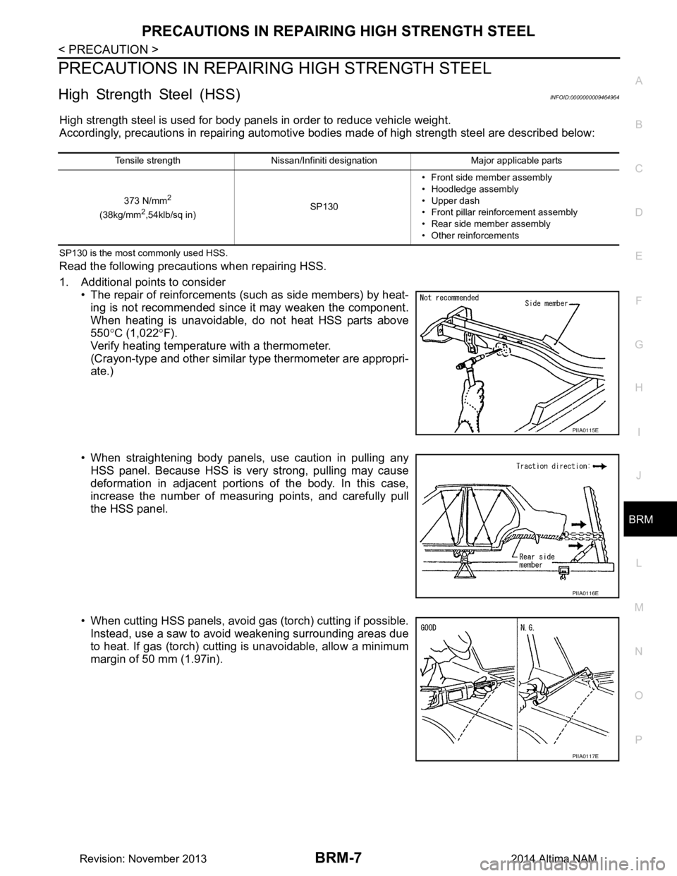
High strength steel is used for body panel s in order to reduce vehicle weight.
Accordingly, precautions in repairing automotive bodies made of high strength steel are described below:
SP130 is the most commonly used HSS.
Read the following precautions when repairing HSS.
1. Additional points to consider • The repair of reinforcements (such as side members) by heat-
ing is not recommended since it may weaken the component.
When heating is unavoidable, do not heat HSS parts above
550 °C (1,022 °F).
Verify heating temperature with a thermometer.
(Crayon-type and other similar type thermometer are appropri-
ate.)
• When straightening body panels, use caution in pulling any HSS panel. Because HSS is very strong, pulling may cause
deformation in adjacent portions of the body. In this case,
increase the number of measuring points, and carefully pull
the HSS panel.
• When cutting HSS panels, avoid gas (torch) cutting if possible. Instead, use a saw to avoid weakening surrounding areas due
to heat. If gas (torch) cutting is unavoidable, allow a minimum
margin of 50 mm (1.97in).
Tensile strength Nissan/Infiniti designation Major applicable parts
373 N/mm
2
(38kg/mm2,54klb/sq in) SP130• Front side member assembly
• Hoodledge assembly
• Upper dash
• Front pillar reinforcement assembly
• Rear side member assembly
• Other reinforcements
PIIA0115E
PIIA0116E
PIIA0117E
Revision: November 20132014 Altima NAM
Page 286 of 4801
BRM-8
< PRECAUTION >
PRECAUTIONS IN REPAIRING HIGH STRENGTH STEEL
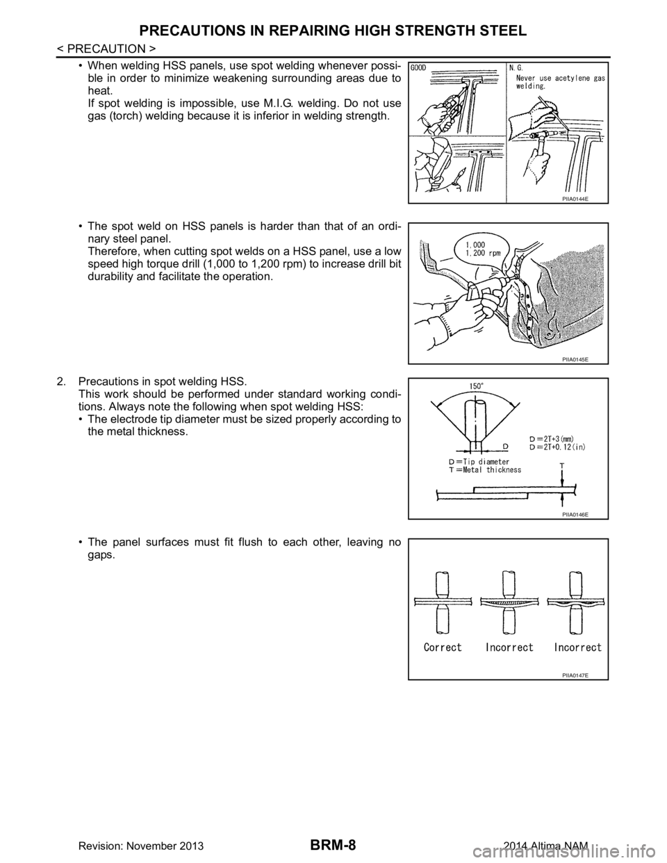
• When welding HSS panels, use spot welding whenever possi-ble in order to minimize weakening surrounding areas due to
heat.
If spot welding is impossible, use M.I.G. welding. Do not use
gas (torch) welding because it is inferior in welding strength.
• The spot weld on HSS panels is harder than that of an ordi- nary steel panel.
Therefore, when cutting spot welds on a HSS panel, use a low
speed high torque drill (1,000 to 1,200 rpm) to increase drill bit
durability and facilitate the operation.
2. Precautions in spot welding HSS. This work should be performed under standard working condi-
tions. Always note the following when spot welding HSS:
• The electrode tip diameter must be sized properly according to the metal thickness.
• The panel surfaces must fit flush to each other, leaving no gaps.
PIIA0144E
PIIA0145E
PIIA0146E
PIIA0147E
Revision: November 20132014 Altima NAM