hood release NISSAN TEANA 2014 Service Manual
[x] Cancel search | Manufacturer: NISSAN, Model Year: 2014, Model line: TEANA, Model: NISSAN TEANA 2014Pages: 4801, PDF Size: 51.2 MB
Page 786 of 4801
DLK-18
< SYSTEM DESCRIPTION >
COMPONENT PARTS
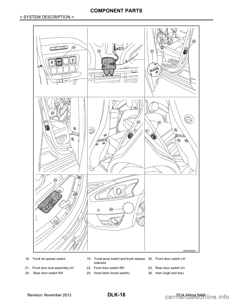
18. Trunk lid opener switch 19. Trunk lamp switch and trunk release solenoid 20. Front door switch LH
21. Front door lock assembly LH 22. Front door switch RH 23. Rear door switch LH
24. Rear door switch RH 25. Hood latch (hood switch) 26. Horn (high and low)
AWKIA2688ZZ
Revision: November 20132014 Altima NAMRevision: November 20132014 Altima NAM
Page 864 of 4801
DLK-96
< DTC/CIRCUIT DIAGNOSIS >
B26FE HOOD SWITCH
3. Check continuity between IPDM E/R harness connector and ground.
Is the inspection result normal?
YES >> Replace IPDM E/R. Refer to PCS-32, "Removal and Installation".
NO >> Repair or replace harness.
3.CHECK HOOD SWITCH GROUND CIRCUIT
Check continuity between hood switch harness connector and ground.
Is the inspection result normal?
YES >> GO TO 4.
NO >> Repair or replace harness.
4.CHECK HOOD SWITCH
Refer to DLK-96, "Component Inspection"
.
Is the inspection result normal?
YES >> GO TO 5.
NO >> Replace hood switch. Refer to DLK-176, "HOOD LOCK CONTROL : Removal and Installation"
.
5.CHECK BCM CONFIGURATION
Refer to BCS-66, "CONFIGURATION (BCM) : Configuration list"
.
>> Inspection End.
Component InspectionINFOID:0000000009461822
1.CHECK HOOD SWITCH
1. Turn ignition switch OFF.
2. Disconnect hood switch connector.
3. Check continuity between hood switch terminals.
Is the inspection result normal?
YES >> Inspection End.
NO >> Replace hood switch. Refer to DLK-176, "HOOD LOCK CONTROL : Removal and Installation"
.
IPDM E/R
GroundContinuity
Connector Terminal
E201 94
No
96
Hood switch
GroundContinuity
Connector Terminal
E248 3 Yes
Hood switch Condition Continuity
Te r m i n a l
1 3 Hood switch Press No
1 3 Hood switch Release Yes
2 3 Hood switch Press No
2 3 Hood switch Release Yes
Revision: November 20132014 Altima NAMRevision: November 20132014 Altima NAM
Page 941 of 4801
HOOD
DLK-173
< REMOVAL AND INSTALLATION >
C
D E
F
G H
I
J
L
M A
B
DLK
N
O P
2. Remove cowl top side trim covers (LH/RH). Refer to EXT-24, "Removal and Installation".
3. Loosen hood hinge (LH/RH) nuts and bolts. NOTE:
The anticorrosive agent applied between the hoodledge and the hood hinges also acts as an adhesive.
This seal must be broken before the hinges will move.
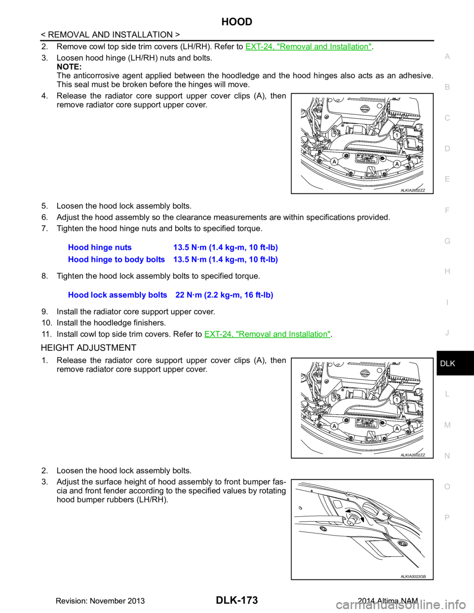
4. Release the radiator core support upper cover clips (A), then remove radiator core support upper cover.
5. Loosen the hood lock assembly bolts.
6. Adjust the hood assembly so the clearance m easurements are within specifications provided.
7. Tighten the hood hinge nuts and bolts to specified torque.
8. Tighten the hood lock assembly bolts to specified torque.
9. Install the radiator core support upper cover.
10. Install the hoodledge finishers.
11. Install cowl top side trim covers. Refer to EXT-24, "Removal and Installation"
.
HEIGHT ADJUSTMENT
1. Release the radiator core support upper cover clips (A), then
remove radiator core support upper cover.
2. Loosen the hood lock assembly bolts.
3. Adjust the surface height of hood assembly to front bumper fas- cia and front fender according to the specified values by rotating
hood bumper rubbers (LH/RH).
ALKIA2602ZZ
Hood hinge nuts 13.5 N·m (1.4 kg-m, 10 ft-lb)
Hood hinge to body bolts 13.5 N·m (1.4 kg-m, 10 ft-lb)
Hood lock assembly bolts 22 N·m (2.2 kg-m, 16 ft-lb)
ALKIA2602ZZ
ALKIA0023GB
Revision: November 20132014 Altima NAMRevision: November 20132014 Altima NAM
Page 943 of 4801
HOOD
DLK-175
< REMOVAL AND INSTALLATION >
C
D E
F
G H
I
J
L
M A
B
DLK
N
O P
• After installation, perform hood assem bly adjustment procedure. Refer to DLK-172, "HOOD ASSEM-
BLY : Adjustment".
HOOD SUPPORT ROD
HOOD SUPPORT ROD : Removal and InstallationINFOID:0000000009461926
REMOVAL
1. Support hood assembly using a suitable tool.
WARNING:
Bodily injury may occur if hood assembly is not supported properly when removing hood support
rod.
2. Rotate and remove hood support rod from grommet.
3. Release tab and remove grommet from hood hinge, if necessary.
INSTALLATION
Installation is in the reverse order of removal.
HOOD LOCK CONTROL
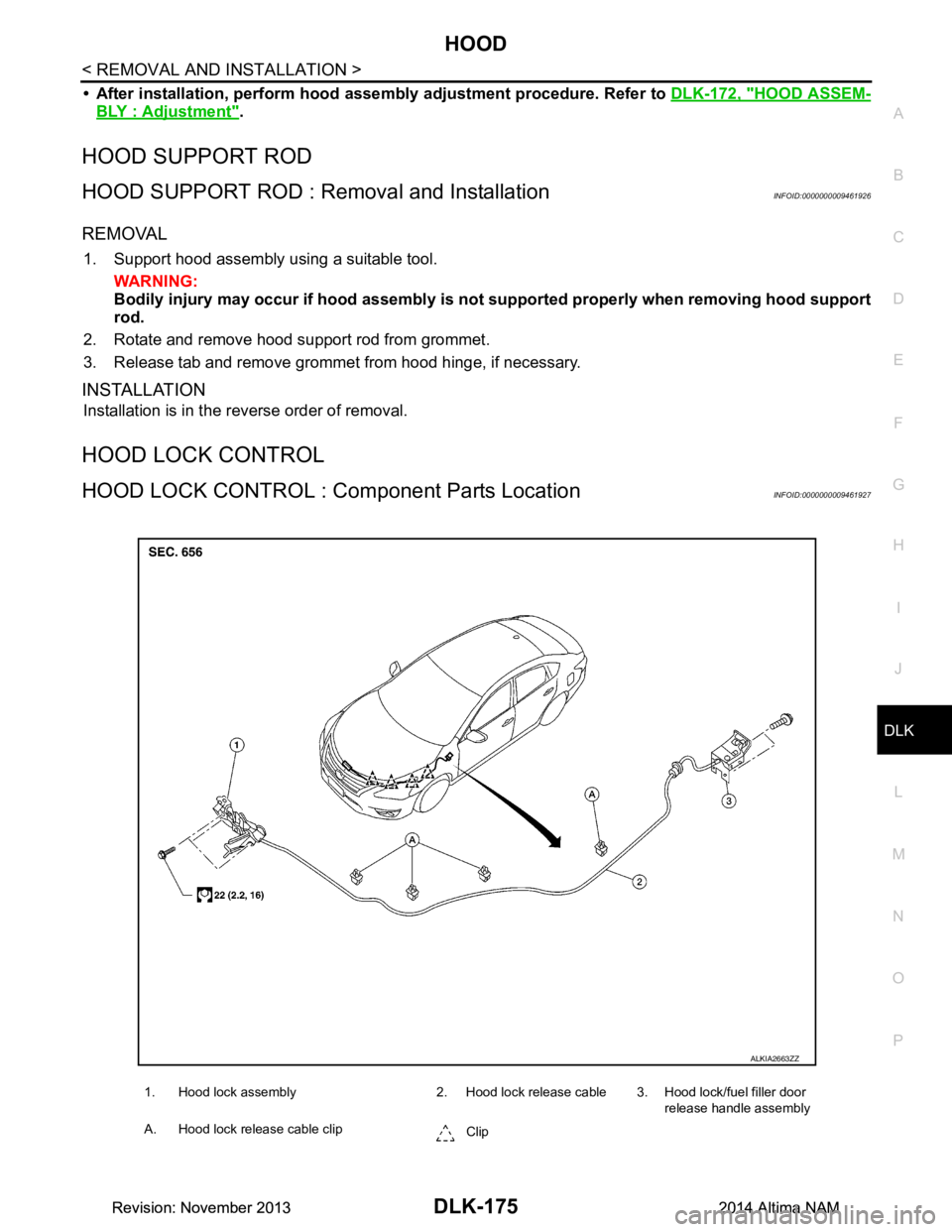
HOOD LOCK CONTROL : Co mponent Parts LocationINFOID:0000000009461927
1. Hood lock assembly 2. Hood lock release cable 3. Hood lock/fuel filler door
release handle assembly
A. Hood lock release cable clip Clip
ALKIA2663ZZ
Revision: November 20132014 Altima NAMRevision: November 20132014 Altima NAM
Page 944 of 4801
DLK-176
< REMOVAL AND INSTALLATION >
HOOD
HOOD LOCK CONTROL : Re moval and Installation
INFOID:0000000009461928
REMOVAL
1. Release the radiator core support upper cover clips, then remove the radiator core support upper cover.
2. Remove the hoodledge finisher clips (LH), then remove the hoodledge finisher LH.
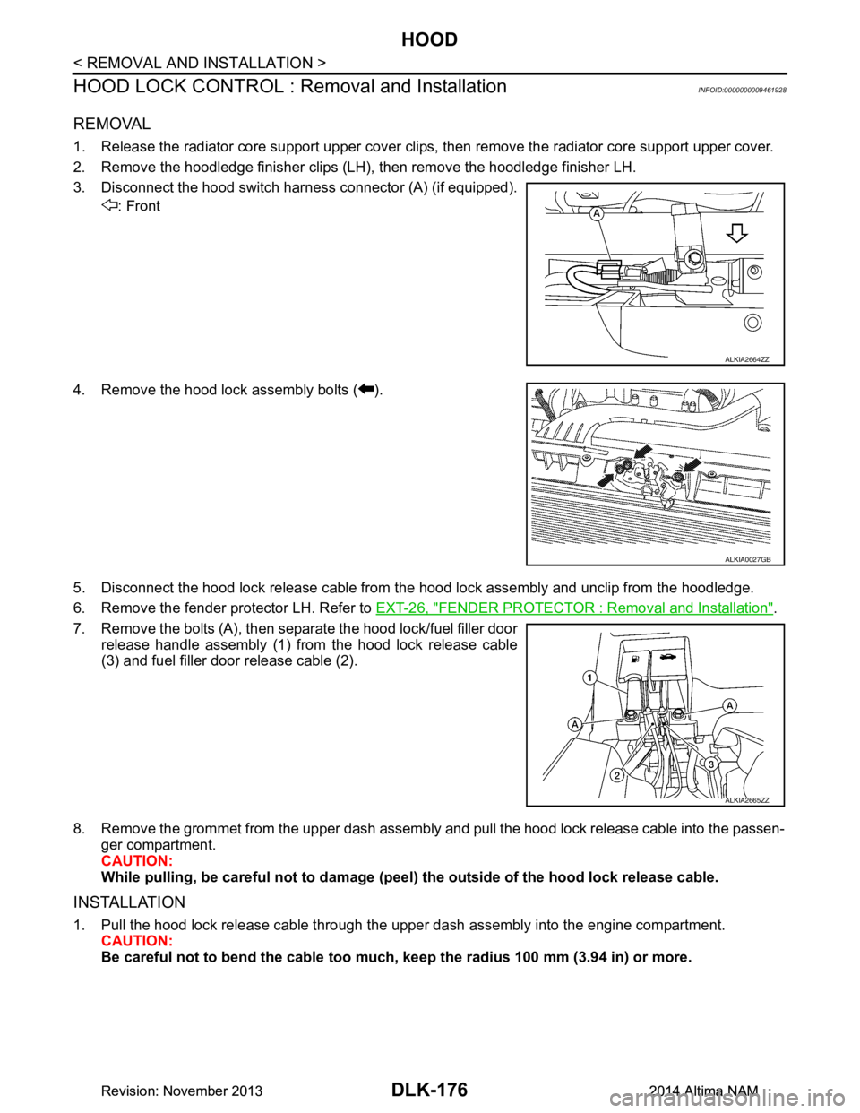
3. Disconnect the hood switch harness connector (A) (if equipped). : Front
4. Remove the hood lock assembly bolts ( ).
5. Disconnect the hood lock release cable from t he hood lock assembly and unclip from the hoodledge.
6. Remove the fender protector LH. Refer to EXT-26, "FENDER PROTECTOR : Removal and Installation"
.
7. Remove the bolts (A), then separate the hood lock/fuel filler door release handle assembly (1) from the hood lock release cable
(3) and fuel filler door release cable (2).
8. Remove the grommet from the upper dash assembly and pull the hood lock release cable into the passen- ger compartment.
CAUTION:
While pulling, be careful no t to damage (peel) the outsid e of the hood lock release cable.
INSTALLATION
1. Pull the hood lock release cable through the upper dash assembly into the engine compartment.
CAUTION:
Be careful not to bend the cable too much , keep the radius 100 mm (3.94 in) or more.
ALKIA2664ZZ
ALKIA0027GB
ALKIA2665ZZ
Revision: November 20132014 Altima NAMRevision: November 20132014 Altima NAM
Page 945 of 4801
HOOD
DLK-177
< REMOVAL AND INSTALLATION >
C
D E
F
G H
I
J
L
M A
B
DLK
N
O P
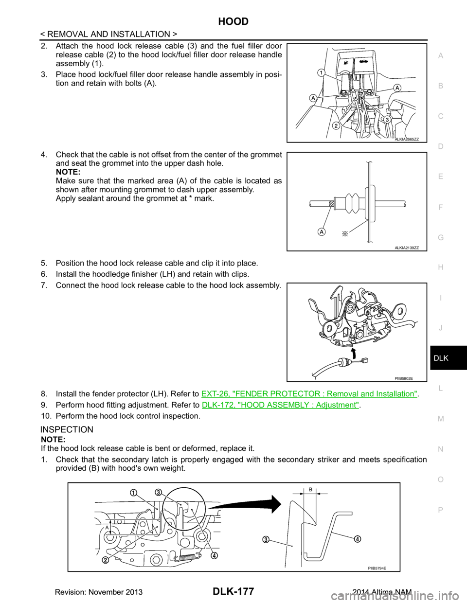
2. Attach the hood lock release cable (3) and the fuel filler door release cable (2) to the hood lock/fuel filler door release handle
assembly (1).
3. Place hood lock/fuel filler door release handle assembly in posi- tion and retain with bolts (A).
4. Check that the cable is not offset from the center of the grommet
and seat the grommet into the upper dash hole.
NOTE:
Make sure that the marked area (A) of the cable is located as
shown after mounting grommet to dash upper assembly.
Apply sealant around the grommet at * mark.
5. Position the hood lock release cable and clip it into place.
6. Install the hoodledge finisher (LH) and retain with clips.
7. Connect the hood lock release cable to the hood lock assembly.
8. Install the fender protector (LH). Refer to EXT-26, "FENDER PROTECTOR : Removal and Installation"
.
9. Perform hood fitting adjustment. Refer to DLK-172, "HOOD ASSEMBLY : Adjustment"
.
10. Perform the hood lock control inspection.
INSPECTION
NOTE:
If the hood lock release cable is bent or deformed, replace it.
1. Check that the secondary latch is properly engaged wi th the secondary striker and meets specification
provided (B) with hood's own weight.
ALKIA2665ZZ
ALKIA2139ZZ
PIIB5802E
PIIB5794E
Revision: November 20132014 Altima NAMRevision: November 20132014 Altima NAM
Page 946 of 4801
DLK-178
< REMOVAL AND INSTALLATION >
HOOD
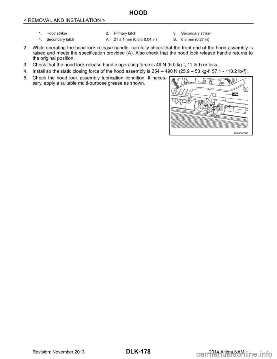
2. While operating the hood lock release handle, carefully check that the front end of the hood assembly is
raised and meets the specification provided (A). Al so check that the hood lock release handle returns to
the original position.
3. Check that the hood lock release handle operating force is 49 N (5.0 kg-f, 11 lb-f) or less.
4. Install so the static closing force of the hood assembly is 254 – 490 N (25.9 – 50 kg-f, 57.1 - 110.2 lb-f).
5. Check the hood lock assembly lubrication condition. If neces- sary, apply a suitable multi-purpose grease as shown.
1. Hood striker 2. Primary latch 3. Secondary striker
4. Secondary latch A. 21 ± 1 mm (0.8 ± 0.04 in) B. 6.8 mm (0.27 in)
ALKIA0028GB
Revision: November 20132014 Altima NAMRevision: November 20132014 Altima NAM
Page 978 of 4801
DLK-210
< REMOVAL AND INSTALLATION >
TRUNK LID
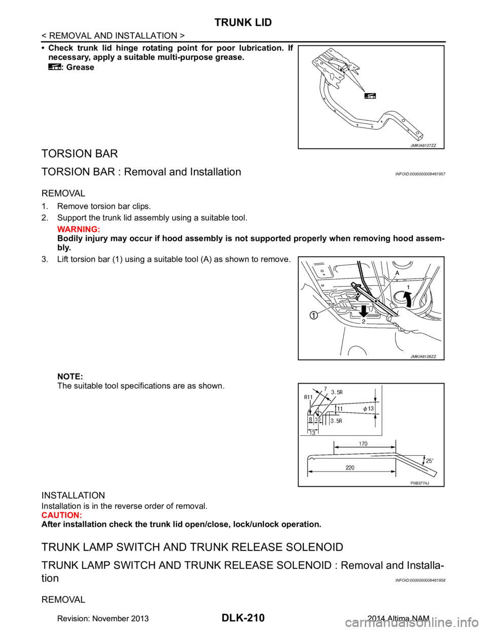
• Check trunk lid hinge rotating point for poor lubrication. If
necessary, apply a suitable multi-purpose grease.
: Grease
TORSION BAR
TORSION BAR : Remova l and InstallationINFOID:0000000009461957
REMOVAL
1. Remove torsion bar clips.
2. Support the trunk lid assembly using a suitable tool. WARNING:
Bodily injury may occur if hood assembly is not supported properly when removing hood assem-
bly.
3. Lift torsion bar (1) using a suitable tool (A) as shown to remove.
NOTE:
The suitable tool specifications are as shown.
INSTALLATION
Installation is in the reverse order of removal.
CAUTION:
After installation check the trunk li d open/close, lock/unlock operation.
TRUNK LAMP SWITCH AND TRUNK RELEASE SOLENOID
TRUNK LAMP SWITCH AND TRUNK RELEASE SOLENOID : Removal and Installa-
tion
INFOID:0000000009461958
REMOVAL
JMKIA8127ZZ
JMKIA8128ZZ
PIIB3774J
Revision: November 20132014 Altima NAMRevision: November 20132014 Altima NAM
Page 1283 of 4801
![NISSAN TEANA 2014 Service Manual
P0139 HO2S2EC-283
< DTC/CIRCUIT DIAGNOSIS > [QR25DE]
C
D E
F
G H
I
J
K L
M A
EC
NP
O
10. Release the accelerator pedal fully at least 5 seconds.
CAUTION:
• Enable engine brake.
• Always drive NISSAN TEANA 2014 Service Manual
P0139 HO2S2EC-283
< DTC/CIRCUIT DIAGNOSIS > [QR25DE]
C
D E
F
G H
I
J
K L
M A
EC
NP
O
10. Release the accelerator pedal fully at least 5 seconds.
CAUTION:
• Enable engine brake.
• Always drive](/img/5/57390/w960_57390-1282.png)
P0139 HO2S2EC-283
< DTC/CIRCUIT DIAGNOSIS > [QR25DE]
C
D E
F
G H
I
J
K L
M A
EC
NP
O
10. Release the accelerator pedal fully at least 5 seconds.
CAUTION:
• Enable engine brake.
• Always drive carefully.
• Never apply brake when releasing the accelerator pedal.
11. Repeat step 9 and 10 at least 8 times.
12. Check the following item of “DATA MONITOR”.
Is
“CMPLT” displayed on CONSULT screen?
YES >> GO TO 6.
NO-1: “CMPLT” is not displayed on DIAG 1>>Perform DTC confirmation procedure again.
NO-2: “CMPLT” is not displayed on DIAG 2>>GO TO 4.
4.PERFORM DTC WORK SUPPORT
1. Open engine hood.
2. Select “HO2S2 (B1) P0139” in “DTC WORK SUPPORT” mode of “ENGINE” using CONSULT.
3. Start engine and follow the instruction of CONSULT display. NOTE:
It will take at most 10 minutes until “COMPLETED” is displayed.
Is
“COMPLETED” displayed on CONSULT screen?
YES >> GO TO 6.
NO >> GO TO 5.
5.PERFORM DTC CONFIRMATION PROCEDURE AGAIN
1. Turn ignition switch OFF and leave the vehicle in a cool place (soak the vehicle).
2. Perform DTC confirmation procedure again.
>> GO TO 3.
6.PERFORM SELF-DIAGNOSIS
With CONSULT
Perform ECM self-diagnosis.
Is DTC
“P0139” detected?
YES >> Proceed to EC-284, "Diagnosis Procedure".
NO >> INSPECTION END
7.PERFORM COMPONENT FUNCTION CHECK
Perform component function check. Refer to EC-283, "Component Function Check"
.
NOTE:
Use component function check to check the overall function of the heated oxygen sensor 2 circuit. During this
check, a 1st trip DTC might not be confirmed.
Is the inspection result normal?
YES >> INSPECTION END
NO >> Proceed to EC-284, "Diagnosis Procedure"
.
Component Function CheckINFOID:0000000009462229
1.PERFORM COMPONENT FUNCTION CHECK-1
Without CONSULT
1. Start engine and warm it up to normal operating temperature.
2. Turn ignition switch OFF and wait at least 10 seconds.
3. Start engine and keep the engine speed between 3,500 and 4,000 rpm for at least 1 minute under no load.
4. Let engine idle for 1 minute.
5. Check the voltage between ECM harness connector and ground as per the following condition.
Data monitor item Status
HO2 S2 DIAG1 (B1) CMPLT
HO2 S2 DIAG2 (B1)
Revision: November 20132014 Altima NAMRevision: November 20132014 Altima NAM
Page 1332 of 4801
![NISSAN TEANA 2014 Service Manual
EC-332
< DTC/CIRCUIT DIAGNOSIS >[QR25DE]
P0420 THREE WAY CATALYST FUNCTION
P0420 THREE WAY CATALYST FUNCTION
DTC LogicINFOID:0000000009462266
DTC DETECTION LOGIC
The ECM monitors the switching freque NISSAN TEANA 2014 Service Manual
EC-332
< DTC/CIRCUIT DIAGNOSIS >[QR25DE]
P0420 THREE WAY CATALYST FUNCTION
P0420 THREE WAY CATALYST FUNCTION
DTC LogicINFOID:0000000009462266
DTC DETECTION LOGIC
The ECM monitors the switching freque](/img/5/57390/w960_57390-1331.png)
EC-332
< DTC/CIRCUIT DIAGNOSIS >[QR25DE]
P0420 THREE WAY CATALYST FUNCTION
P0420 THREE WAY CATALYST FUNCTION
DTC LogicINFOID:0000000009462266
DTC DETECTION LOGIC
The ECM monitors the switching frequency ratio of air fuel ratio (A/F)
sensor 1 and heated oxygen sensor 2.
A three way catalyst (manifold) with high oxygen storage capacity
will indicate a low switching frequency of heated oxygen sensor 2.
As oxygen storage capacity decr eases, the heated oxygen sensor 2
switching frequency will increase.
When the frequency ratio of air fuel ratio (A/F) sensor 1 and heated
oxygen sensor 2 approaches a specif ied limit value, the three way
catalyst (manifold) malfunction is diagnosed.
DTC CONFIRMATION PROCEDURE
1.PRECONDITIONING
If DTC Confirmation Procedure has been previously conducted, always perform the following procedure
before conducting the next test.
1. Turn ignition switch OFF and wait at least 10 seconds.
2. Turn ignition switch ON.
3. Turn ignition switch OFF and wait at least 10 seconds.
Will CONSULT be used?
YES >> GO TO 2.
NO >> GO TO 6.
2.PERFORM DTC CONFIRMATION PROCEDURE-1
With CONSULT
TESTING CONDITION:
Do not hold engine speed for more than the specified minutes below.
1. Start engine and warm it up to the normal operating temperature.
2. Turn ignition switch OFF and wait at least 10 seconds.
3. Turn ignition switch ON.
4. Turn ignition switch OFF and wait at least 10 seconds.
5. Start engine and keep the engine speed between 3,500 and 4,000 rpm for at least 1 minute under no load.
6. Let engine idle for 1 minute.
7. Select “DATA MONITOR” mode of “ENGINE” using CONSULT.
8. Check that “COOLAN TEMP/S” indicates more than 70 °C (158 °F).
If not, warm up engine and go to next step when “C OOLAN TEMP/S” indication reaches to 70°C (158 °F).
9. Open engine hood.
10. Select “DTC & SRT CONFIRMATION” then “SRT WORK SUPPORT” mode of “ENGINE” using CON-
SULT.
11. Rev engine up to 2,500 to 3,000 rpm and hold it for 3 consecutive minutes then release the accelerator pedal completely.
12. Check the indication of “CATALYST”.
SEF484YB
DTC No. CONSULT screen terms
(Trouble diagnosis content) DTC detecting condition Possible cause
P0420 TW CATALYST SYS-B1
(Catalyst system efficiency be-
low threshold bank 1) • Three way catalyst (manifold) does not operate
properly.
• Three way catalyst (manifold) does not have enough oxygen storage capacity. • Three way catalyst (manifold)
• Exhaust tube
• Intake air leaks
• Fuel injector
• Fuel injector leaks
• Spark plug
• Improper ignition timing
Revision: November 20132014 Altima NAMRevision: November 20132014 Altima NAM