Brake NISSAN TERRANO 2002 Service Repair Manual
[x] Cancel search | Manufacturer: NISSAN, Model Year: 2002, Model line: TERRANO, Model: NISSAN TERRANO 2002Pages: 1767, PDF Size: 41.51 MB
Page 1508 of 1767
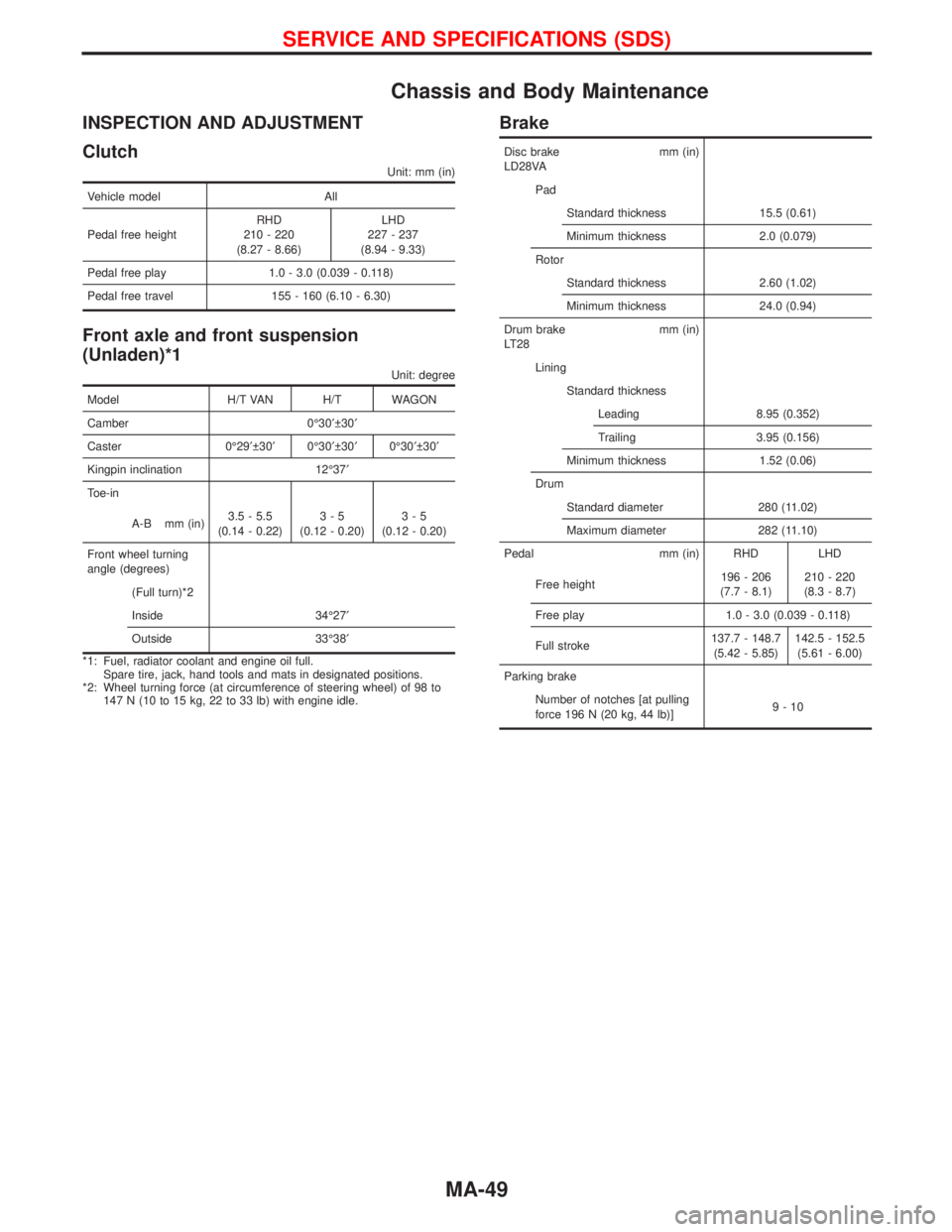
Chassis and Body Maintenance
INSPECTION AND ADJUSTMENT
Clutch
Unit: mm (in)
Vehicle model All
Pedal free heightRHD
210 - 220
(8.27 - 8.66)LHD
227 - 237
(8.94 - 9.33)
Pedal free play 1.0 - 3.0 (0.039 - 0.118)
Pedal free travel 155 - 160 (6.10 - 6.30)
Front axle and front suspension
(Unladen)*1
Unit: degree
Model H/T VAN H/T WAGON
Camber 0É30¢ 30¢
Caster 0É29¢ 30¢0É30¢ 30¢0É30¢ 30¢
Kingpin inclination 12É37¢
Toe-in
A-B mm (in)3.5 - 5.5
(0.14 - 0.22)3-5
(0.12 - 0.20)3-5
(0.12 - 0.20)
Front wheel turning
angle (degrees)
(Full turn)*2
Inside 34É27¢
Outside 33É38¢
*1: Fuel, radiator coolant and engine oil full.
Spare tire, jack, hand tools and mats in designated positions.
*2: Wheel turning force (at circumference of steering wheel) of 98 to
147 N (10 to 15 kg, 22 to 33 lb) with engine idle.
Brake
Disc brake mm (in)
LD28VA
Pad
Standard thickness 15.5 (0.61)
Minimum thickness 2.0 (0.079)
Rotor
Standard thickness 2.60 (1.02)
Minimum thickness 24.0 (0.94)
Drum brake mm (in)
LT28
Lining
Standard thickness
Leading 8.95 (0.352)
Trailing 3.95 (0.156)
Minimum thickness 1.52 (0.06)
Drum
Standard diameter 280 (11.02)
Maximum diameter 282 (11.10)
Pedal mm (in) RHD LHD
Free height196 - 206
(7.7 - 8.1)210 - 220
(8.3 - 8.7)
Free play 1.0 - 3.0 (0.039 - 0.118)
Full stroke137.7 - 148.7
(5.42 - 5.85)142.5 - 152.5
(5.61 - 6.00)
Parking brake
Number of notches [at pulling
force 196 N (20 kg, 44 lb)]9-10
SERVICE AND SPECIFICATIONS (SDS)
MA-49
Page 1509 of 1767
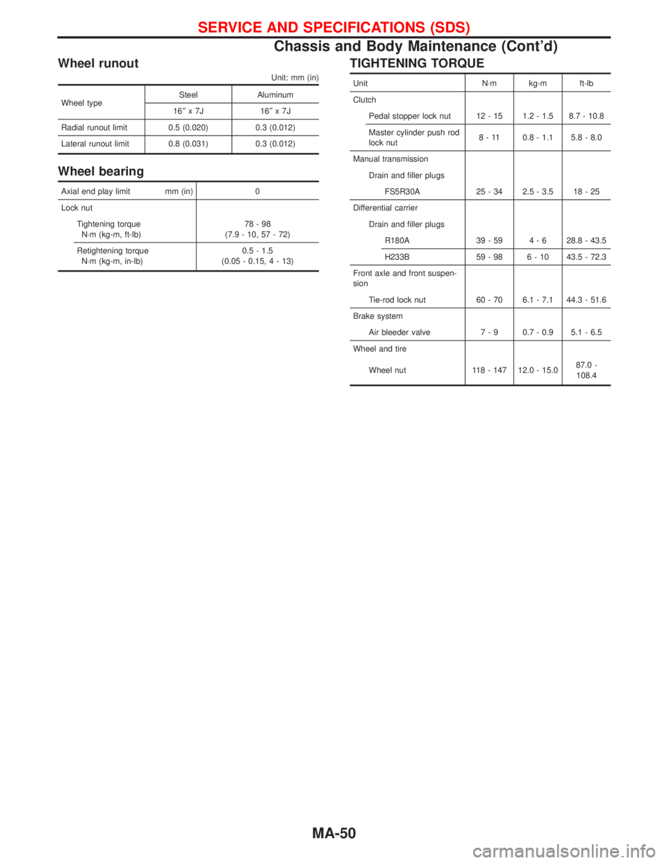
Wheel runout
Unit: mm (in)
Wheel typeSteel Aluminum
16²x7J 16²x7J
Radial runout limit 0.5 (0.020) 0.3 (0.012)
Lateral runout limit 0.8 (0.031) 0.3 (0.012)
Wheel bearing
Axial end play limit mm (in) 0
Lock nut
Tightening torque
N×m (kg-m, ft-lb)78-98
(7.9 - 10, 57 - 72)
Retightening torque
N×m (kg-m, in-lb)0.5 - 1.5
(0.05 - 0.15,4-13)
TIGHTENING TORQUE
Unit N×m kg-m ft-lb
Clutch
Pedal stopper lock nut 12 - 15 1.2 - 1.5 8.7 - 10.8
Master cylinder push rod
lock nut8 - 11 0.8 - 1.1 5.8 - 8.0
Manual transmission
Drain and filler plugs
FS5R30A 25 - 34 2.5 - 3.5 18 - 25
Differential carrier
Drain and filler plugs
R180A 39 - 59 4 - 6 28.8 - 43.5
H233B 59 - 98 6 - 10 43.5 - 72.3
Front axle and front suspen-
sion
Tie-rod lock nut 60 - 70 6.1 - 7.1 44.3 - 51.6
Brake system
Air bleeder valve 7 - 9 0.7 - 0.9 5.1 - 6.5
Wheel and tire
Wheel nut 118 - 147 12.0 - 15.087.0 -
108.4
SERVICE AND SPECIFICATIONS (SDS)
Chassis and Body Maintenance (Cont'd)
MA-50
Page 1607 of 1767
Precautions
IWhen installing each rubber part, final tightening must be car-
ried out under unladen condition* with tires on ground.
* Fuel, radiator coolant and engine oil full. Spare tire, jack,
hand tools and mats in designated positions.
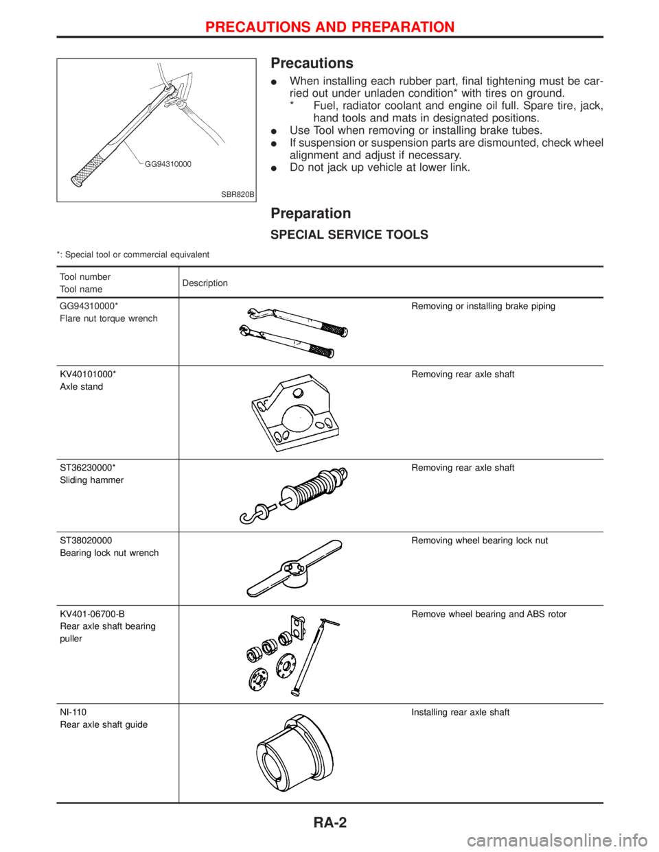
IUse Tool when removing or installing brake tubes.
IIf suspension or suspension parts are dismounted, check wheel
alignment and adjust if necessary.
IDo not jack up vehicle at lower link.
Preparation
SPECIAL SERVICE TOOLS
*: Special tool or commercial equivalent
Tool number
Tool nameDescription
GG94310000*
Flare nut torque wrench
Removing or installing brake piping
KV40101000*
Axle stand
Removing rear axle shaft
ST36230000*
Sliding hammer
Removing rear axle shaft
ST38020000
Bearing lock nut wrench
Removing wheel bearing lock nut
KV401-06700-B
Rear axle shaft bearing
puller
Remove wheel bearing and ABS rotor
NI-110
Rear axle shaft guide
Installing rear axle shaft
SBR820B
PRECAUTIONS AND PREPARATION
RA-2
Page 1612 of 1767
Removal
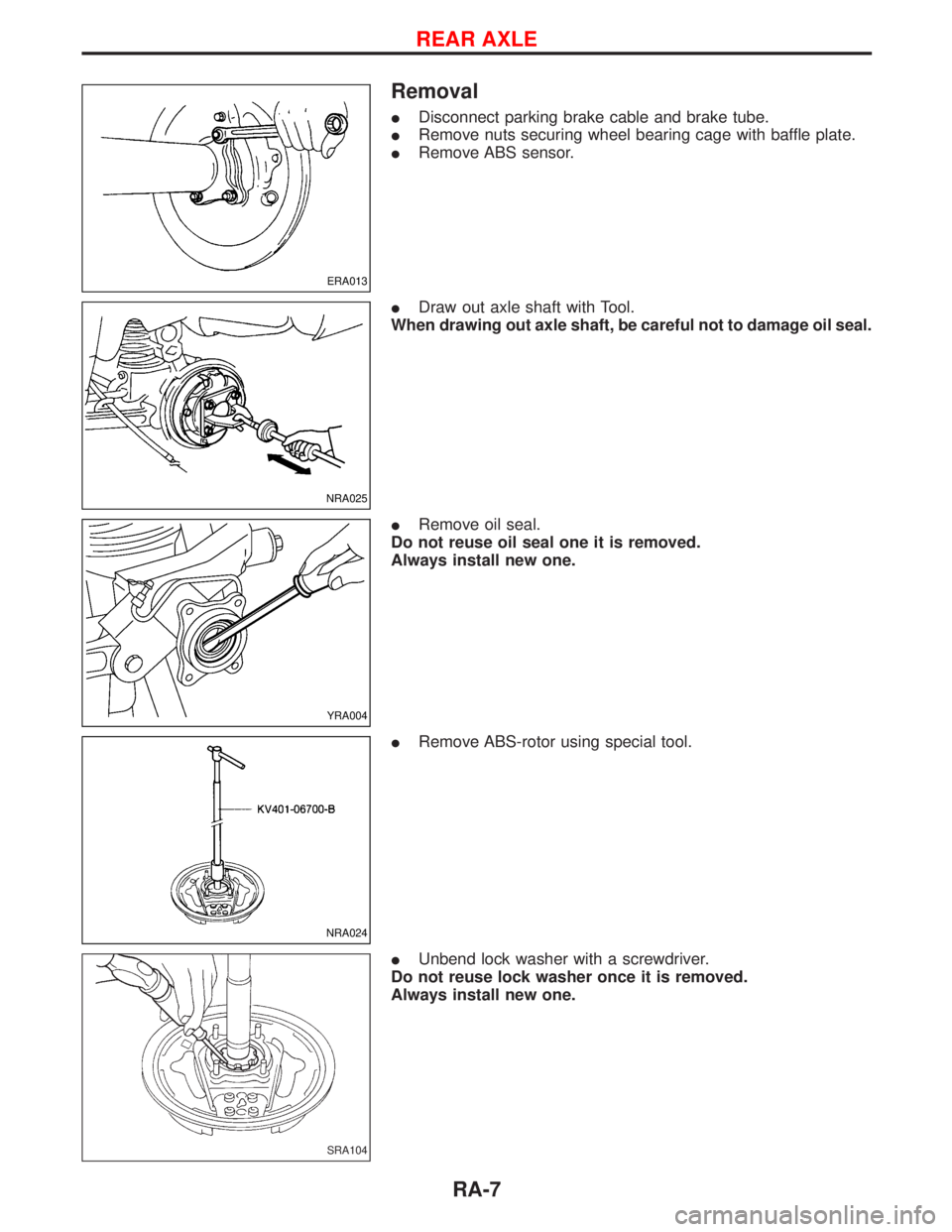
IDisconnect parking brake cable and brake tube.
IRemove nuts securing wheel bearing cage with baffle plate.
IRemove ABS sensor.
IDraw out axle shaft with Tool.
When drawing out axle shaft, be careful not to damage oil seal.
IRemove oil seal.
Do not reuse oil seal one it is removed.
Always install new one.
IRemove ABS-rotor using special tool.
IUnbend lock washer with a screwdriver.
Do not reuse lock washer once it is removed.
Always install new one.
ERA013
NRA025
YRA004
NRA024
SRA104
REAR AXLE
RA-7
Page 1615 of 1767
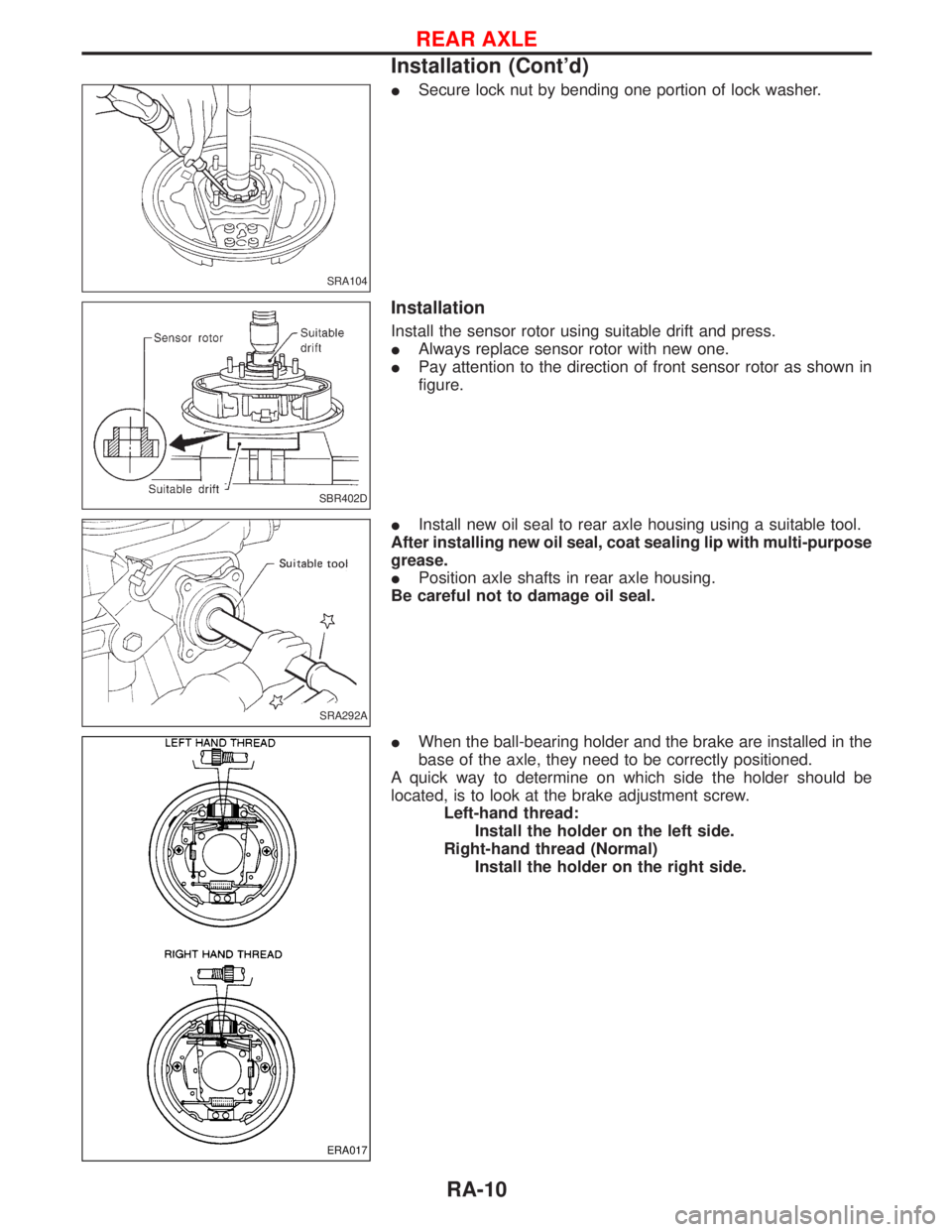
ISecure lock nut by bending one portion of lock washer.
Installation
Install the sensor rotor using suitable drift and press.
IAlways replace sensor rotor with new one.
IPay attention to the direction of front sensor rotor as shown in
figure.
IInstall new oil seal to rear axle housing using a suitable tool.
After installing new oil seal, coat sealing lip with multi-purpose
grease.
IPosition axle shafts in rear axle housing.
Be careful not to damage oil seal.
IWhen the ball-bearing holder and the brake are installed in the
base of the axle, they need to be correctly positioned.
A quick way to determine on which side the holder should be
located, is to look at the brake adjustment screw.
Left-hand thread:
Install the holder on the left side.
Right-hand thread (Normal)
Install the holder on the right side.
SRA104
SBR402D
SRA292A
ERA017
REAR AXLE
Installation (Cont'd)
RA-10
Page 1617 of 1767
Removal and Installation
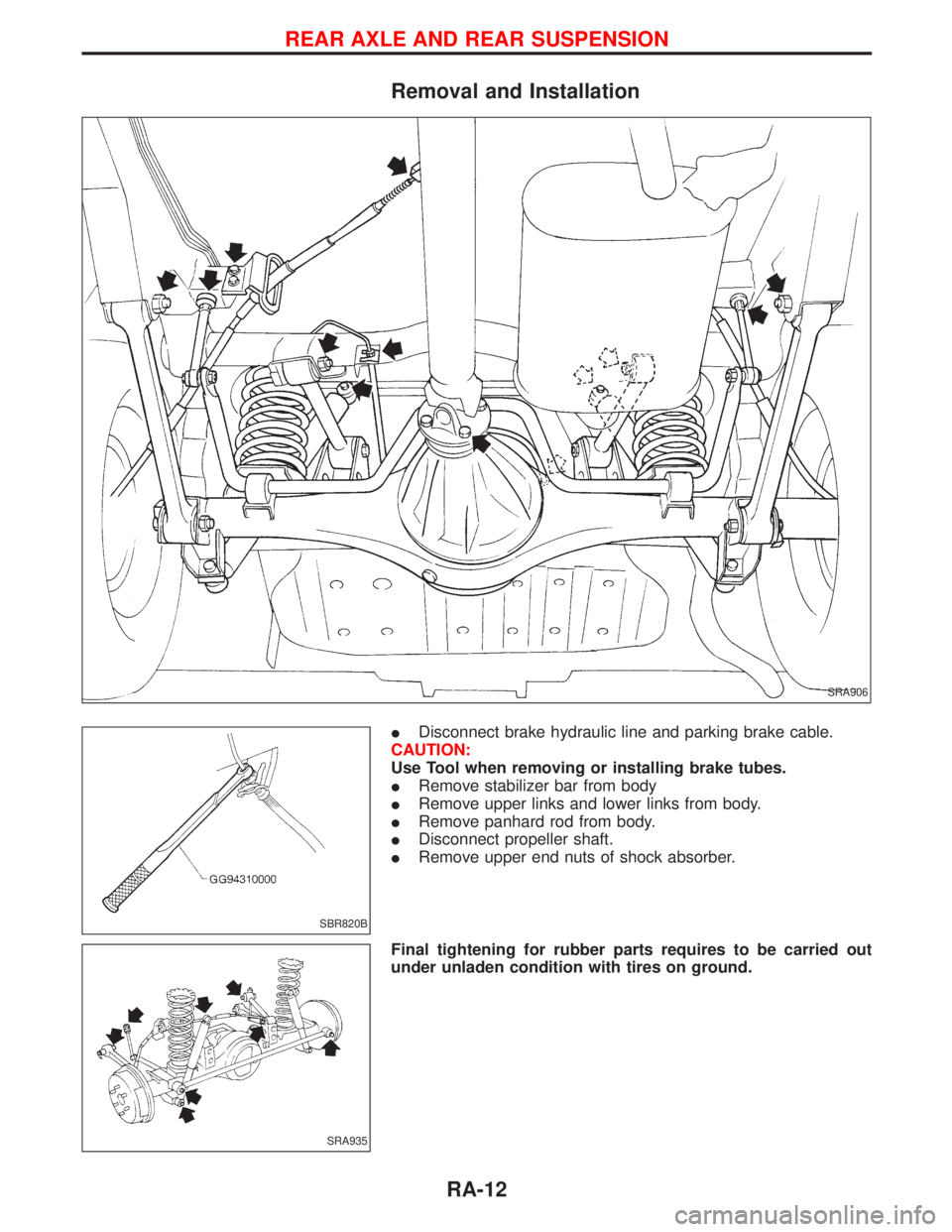
IDisconnect brake hydraulic line and parking brake cable.
CAUTION:
Use Tool when removing or installing brake tubes.
IRemove stabilizer bar from body
IRemove upper links and lower links from body.
IRemove panhard rod from body.
IDisconnect propeller shaft.
IRemove upper end nuts of shock absorber.
Final tightening for rubber parts requires to be carried out
under unladen condition with tires on ground.
SRA906
SBR820B
SRA935
REAR AXLE AND REAR SUSPENSION
RA-12
Page 1717 of 1767
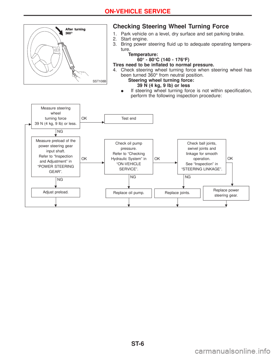
Checking Steering Wheel Turning Force
1. Park vehicle on a level, dry surface and set parking brake.
2. Start engine.
3. Bring power steering fluid up to adequate operating tempera-
ture.
Temperature:
60É - 80ÉC (140 - 176ÉF)
Tires need to be inflated to normal pressure.
4. Check steering wheel turning force when steering wheel has
been turned 360É from neutral position.
Steering wheel turning force:
39 N (4 kg, 9 lb) or less
IIf steering wheel turning force is not within specification,
perform the following inspection procedure:
E
Measure steering
wheel
turning force
39 N (4 kg, 9 lb) or less.
NG
EOK Test end
Measure preload of the
power steering gear
input shaft.
Refer to ªInspection
and Adjustmentº in
ªPOWER STEERING
GEARº.
NG
EOKCheck oil pump
pressure.
Refer to ªChecking
Hydraulic Systemº in
ªON-VEHICLE
SERVICEº.
NG
EOKCheck ball joints,
swivel joints and
linkage for smooth
operation.
See ªInspectionº in
ªSTEERING LINKAGEº.
NGOK
Adjust preload.Replace oil pump.Replace joints.Replace power
steering gear.
SST108B
H
HHHH
HHHH
ON-VEHICLE SERVICE
ST-6