heater NISSAN TERRANO 2002 Service User Guide
[x] Cancel search | Manufacturer: NISSAN, Model Year: 2002, Model line: TERRANO, Model: NISSAN TERRANO 2002Pages: 1767, PDF Size: 41.51 MB
Page 1246 of 1767
Assembly
PISTON
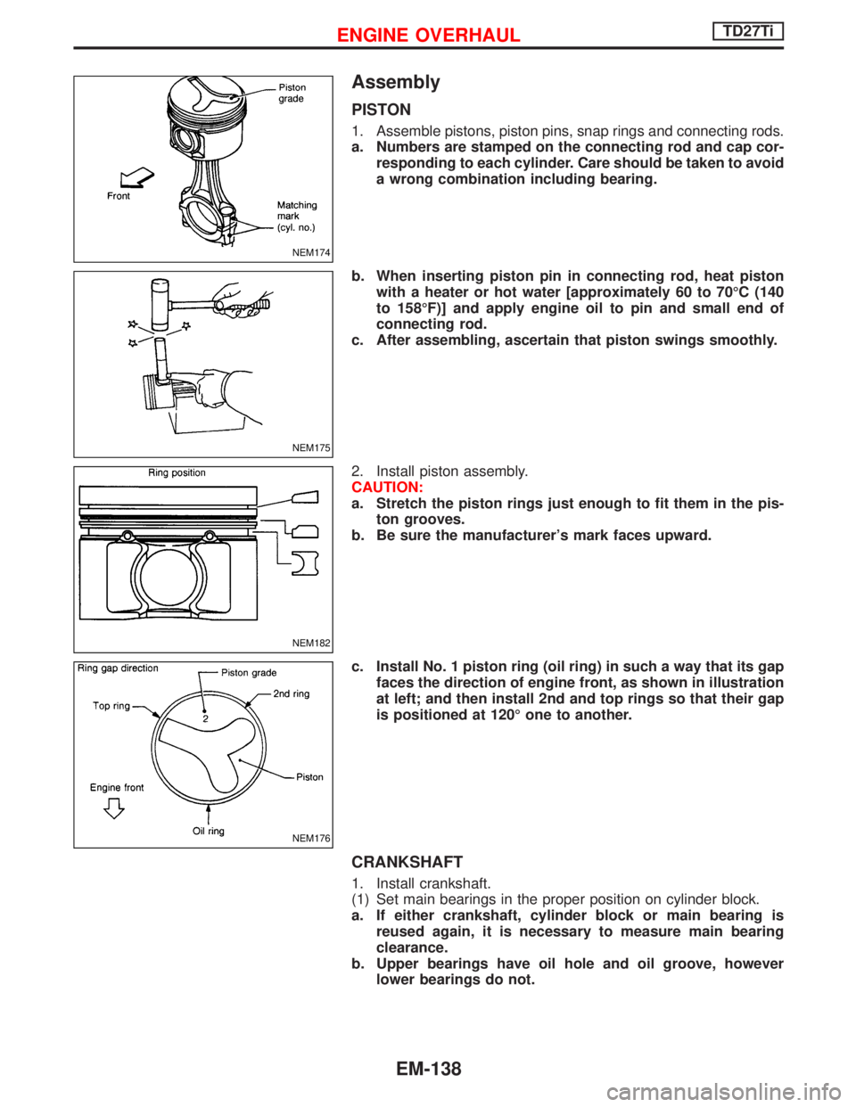
1. Assemble pistons, piston pins, snap rings and connecting rods.
a. Numbers are stamped on the connecting rod and cap cor-
responding to each cylinder. Care should be taken to avoid
a wrong combination including bearing.
b. When inserting piston pin in connecting rod, heat piston
with a heater or hot water [approximately 60 to 70ÉC (140
to 158ÉF)] and apply engine oil to pin and small end of
connecting rod.
c. After assembling, ascertain that piston swings smoothly.
2. Install piston assembly.
CAUTION:
a. Stretch the piston rings just enough to fit them in the pis-
ton grooves.
b. Be sure the manufacturer's mark faces upward.
c. Install No. 1 piston ring (oil ring) in such a way that its gap
faces the direction of engine front, as shown in illustration
at left; and then install 2nd and top rings so that their gap
is positioned at 120É one to another.
CRANKSHAFT
1. Install crankshaft.
(1) Set main bearings in the proper position on cylinder block.
a. If either crankshaft, cylinder block or main bearing is
reused again, it is necessary to measure main bearing
clearance.
b. Upper bearings have oil hole and oil groove, however
lower bearings do not.
NEM174
NEM175
NEM182
NEM176
ENGINE OVERHAULTD27Ti
EM-138
Page 1321 of 1767
Precautions for Fuel
DIESEL ENGINE*:
Diesel fuel of at least 50 cetane for ZD30DDTi engine.
* If two types of diesel fuel are available, use summer or winter
fuel properly according to the following temperature conditions.
IAbove þ7ÉC (20ÉF) ... Summer type diesel fuel.
IBelow þ7ÉC (20ÉF) ... Winter type diesel fuel.
CAUTION:
IDo not use home heating oil, gasoline, or other alternate
fuels in your diesel engine. The use of those can cause
engine damage.
IDo not use summer fuel at temperature below þ7ÉC (20ÉF).
The cold temperature will cause wax to form in the fuel. As
a result, it may prevent the engine from running smoothly.
IDo not add gasoline or other alternate fuels to diesel fuel.
Precautions for Engine Oils
Prolonged and repeated contact with mineral oil will result in the
removal of natural fats from the skin, leading to dryness, irritation
and dermatitis. In addition, used engine oil contains potentially
harmful contaminants which may cause skin cancer. Adequate
means of skin protection and washing facilities must be provided.
HEALTH PROTECTION PRECAUTIONS
1. Avoid prolonged and repeated contact with oils, particularly
used engine oils.
2. Wear protective clothing, including impervious gloves where
practicable.
3. Do not put oily rags in pockets.
4. Avoid contaminating clothes, particularly underwear, with oil.
5. Heavily soiled clothing and oil-impregnated footwear should not
be worn. Overalls must be cleaned regularly.
6. First Aid treatment should be obtained immediately for open
cuts and wounds.
7. Use barrier creams, applying them before each work period, to
help the removal of oil from the skin.
8. Wash with soap and water to ensure all oil is removed (skin
cleansers and nail brushes will help). Preparations containing
lanolin replace the natural skin oils which have been removed.
9. Do not use petrol, kerosine, diesel fuel, gas oil, thinners or sol-
vents for cleaning skin.
10. If skin disorders develop, obtain medical advice without delay.
11. Where practicable, degrease components prior to handling.
12. Where there is a risk of eye contact, eye protection should be
worn, for example, chemical goggles or face shields; in addition
an eye wash facility should be provided.
(For the United Kingdom, see also HSE Cautionary Notice SHW
397 ªEffects of Mineral Oil on the Skinº.)
ENVIRONMENTAL PROTECTION PRECAUTIONS
Burning used engine oil in small space heaters or boilers can be
recommended only for units of approved design. The heating sys-
tem must meet the requirements of HM Inspectorate of Pollution for
small burners of less than 0.4 MW. If in doubt check with the
appropriate local authority and/or manufacturer of the approved
appliance.
PRECAUTIONS
GI-6
Page 1350 of 1767
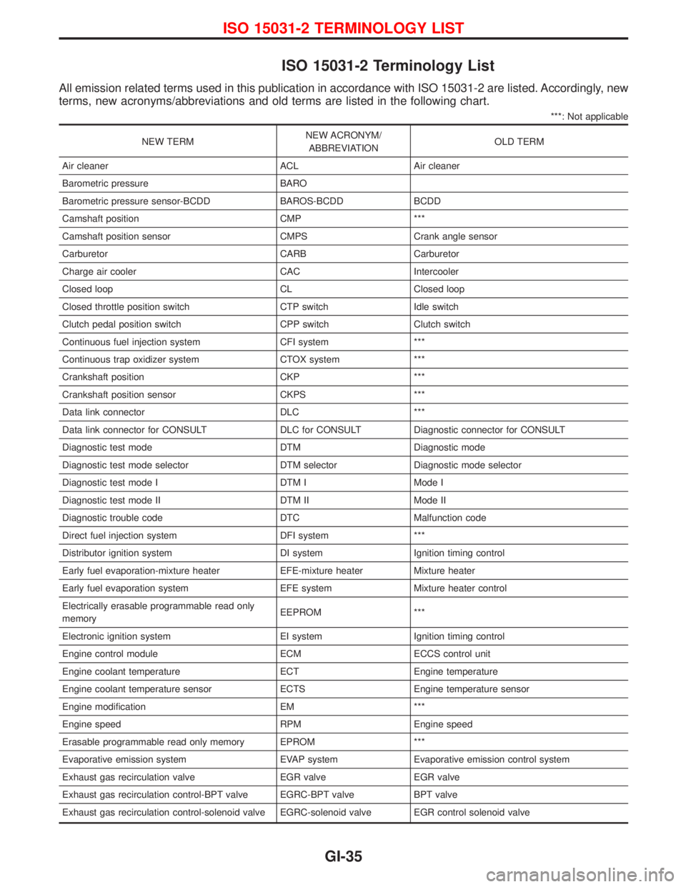
ISO 15031-2 Terminology List
All emission related terms used in this publication in accordance with ISO 15031-2 are listed. Accordingly, new
terms, new acronyms/abbreviations and old terms are listed in the following chart.
***: Not applicable
NEW TERMNEW ACRONYM/
ABBREVIATIONOLD TERM
Air cleaner ACL Air cleaner
Barometric pressure BARO
Barometric pressure sensor-BCDD BAROS-BCDD BCDD
Camshaft position CMP ***
Camshaft position sensor CMPS Crank angle sensor
Carburetor CARB Carburetor
Charge air cooler CAC Intercooler
Closed loop CL Closed loop
Closed throttle position switch CTP switch Idle switch
Clutch pedal position switch CPP switch Clutch switch
Continuous fuel injection system CFI system ***
Continuous trap oxidizer system CTOX system ***
Crankshaft position CKP ***
Crankshaft position sensor CKPS ***
Data link connector DLC ***
Data link connector for CONSULT DLC for CONSULT Diagnostic connector for CONSULT
Diagnostic test mode DTM Diagnostic mode
Diagnostic test mode selector DTM selector Diagnostic mode selector
Diagnostic test mode I DTM I Mode I
Diagnostic test mode II DTM II Mode II
Diagnostic trouble code DTC Malfunction code
Direct fuel injection system DFI system ***
Distributor ignition system DI system Ignition timing control
Early fuel evaporation-mixture heater EFE-mixture heater Mixture heater
Early fuel evaporation system EFE system Mixture heater control
Electrically erasable programmable read only
memoryEEPROM ***
Electronic ignition system EI system Ignition timing control
Engine control module ECM ECCS control unit
Engine coolant temperature ECT Engine temperature
Engine coolant temperature sensor ECTS Engine temperature sensor
Engine modification EM ***
Engine speed RPM Engine speed
Erasable programmable read only memory EPROM ***
Evaporative emission system EVAP system Evaporative emission control system
Exhaust gas recirculation valve EGR valve EGR valve
Exhaust gas recirculation control-BPT valve EGRC-BPT valve BPT valve
Exhaust gas recirculation control-solenoid valve EGRC-solenoid valve EGR control solenoid valve
ISO 15031-2 TERMINOLOGY LIST
GI-35
Page 1354 of 1767
HEATER & AIR CONDITIONER
SECTION
HA
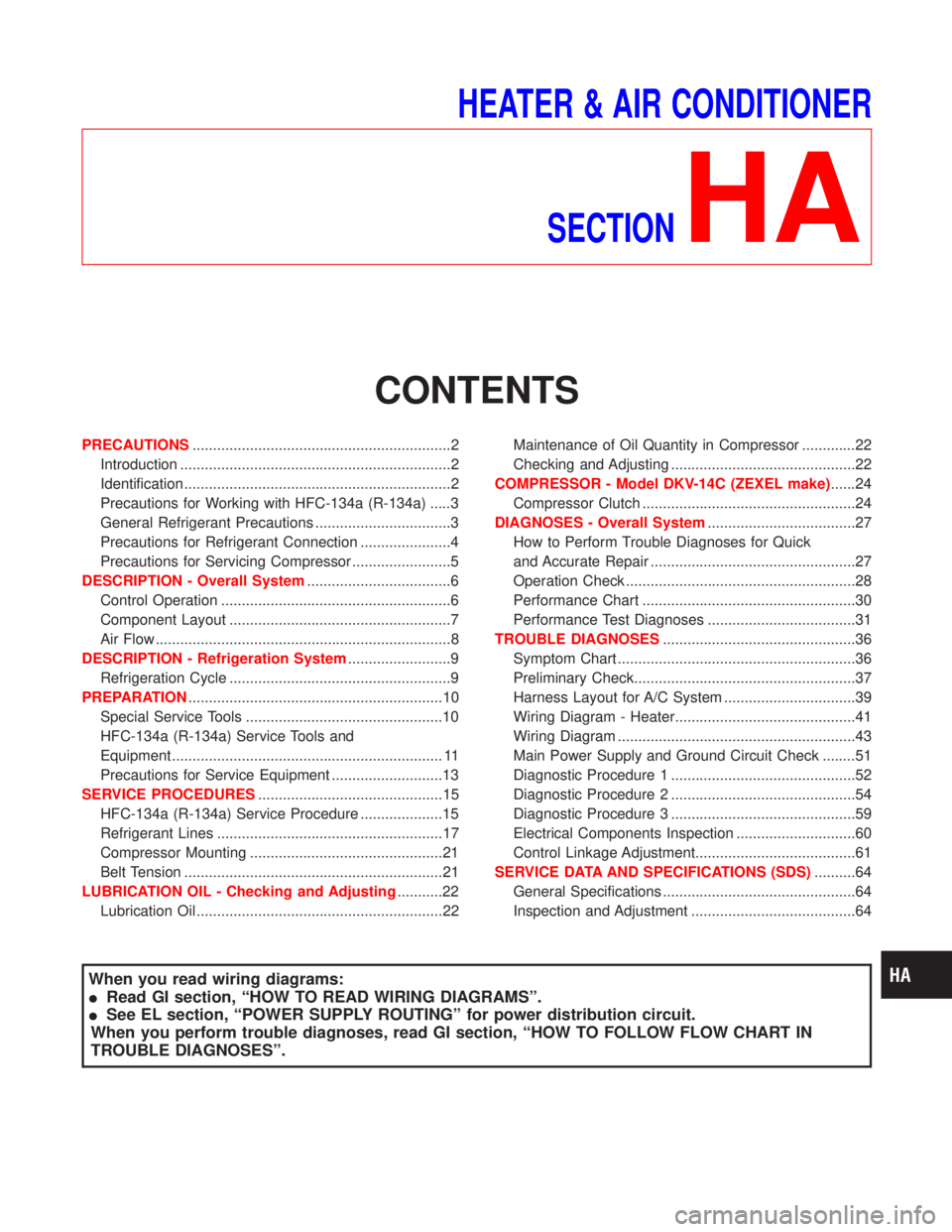
CONTENTS
PRECAUTIONS...............................................................2
Introduction ..................................................................2
Identification .................................................................2
Precautions for Working with HFC-134a (R-134a) .....3
General Refrigerant Precautions .................................3
Precautions for Refrigerant Connection ......................4
Precautions for Servicing Compressor ........................5
DESCRIPTION - Overall System...................................6
Control Operation ........................................................6
Component Layout ......................................................7
Air Flow ........................................................................8
DESCRIPTION - Refrigeration System.........................9
Refrigeration Cycle ......................................................9
PREPARATION..............................................................10
Special Service Tools ................................................10
HFC-134a (R-134a) Service Tools and
Equipment .................................................................. 11
Precautions for Service Equipment ...........................13
SERVICE PROCEDURES.............................................15
HFC-134a (R-134a) Service Procedure ....................15
Refrigerant Lines .......................................................17
Compressor Mounting ...............................................21
Belt Tension ...............................................................21
LUBRICATION OIL - Checking and Adjusting...........22
Lubrication Oil ............................................................22Maintenance of Oil Quantity in Compressor .............22
Checking and Adjusting .............................................22
COMPRESSOR - Model DKV-14C (ZEXEL make)......24
Compressor Clutch ....................................................24
DIAGNOSES - Overall System....................................27
How to Perform Trouble Diagnoses for Quick
and Accurate Repair ..................................................27
Operation Check ........................................................28
Performance Chart ....................................................30
Performance Test Diagnoses ....................................31
TROUBLE DIAGNOSES...............................................36
Symptom Chart ..........................................................36
Preliminary Check......................................................37
Harness Layout for A/C System ................................39
Wiring Diagram - Heater............................................41
Wiring Diagram ..........................................................43
Main Power Supply and Ground Circuit Check ........51
Diagnostic Procedure 1 .............................................52
Diagnostic Procedure 2 .............................................54
Diagnostic Procedure 3 .............................................59
Electrical Components Inspection .............................60
Control Linkage Adjustment.......................................61
SERVICE DATA AND SPECIFICATIONS (SDS)..........64
General Specifications ...............................................64
Inspection and Adjustment ........................................64
When you read wiring diagrams:
IRead GI section, ªHOW TO READ WIRING DIAGRAMSº.
ISee EL section, ªPOWER SUPPLY ROUTINGº for power distribution circuit.
When you perform trouble diagnoses, read GI section, ªHOW TO FOLLOW FLOW CHART IN
TROUBLE DIAGNOSESº.
Page 1394 of 1767

Wiring Diagram Ð Heater
LHD MODELS
YHA400
TROUBLE DIAGNOSES
HA-41
Page 1395 of 1767

RHD MODELS
YHA401
TROUBLE DIAGNOSES
Wiring Diagram Ð Heater (Cont'd)
HA-42
Page 1421 of 1767
F
Fan switch ......................................................HA-60
F/FOG - Wiring diagram .................................EL-51
Final drive disassembly............................PD-15, 37
Final drive pre-inspection .........................PD-15, 37
Final drive removal and installation ...............PD-15
Finisher, interior - See Trim ............................BT-18
Finisher, rear panel .........................................BT-18
Floor trim .........................................................BT-18
Fluid temperature sensor (A/T) .....................AT-141
Fluids .............................................MA-5, 17, 20, 36
Flywheel (clutch) .......................................CL-11, 12
Flywheel runout..............................................EM-94
Fog lamp, front .........................................EL-51, 53
Fog lamp, rear ................................................EL-54
Fork rod (M/T) ................................................MT-13
Forward clutch...............................................AT-157
Front axle ....................................................FA-4, 13
Front bumper ....................................................BT-6
Front case (Transfer) ..................................TF-9, 23
Front combination lamp removal and
installation .....................................................BT-6
Front disc brake .............................................BR-26
Front door .......................................................BT-10
Front Door Trim...............................................BT-19
Front drive shaft (Transfer) .........................TF-9, 19
Front final drive disassembly (4WD) ..............PD-14
Front final drive removal and installa-
tion (4WD) ............................................PD-12, 13
Front fog lamp ..........................................EL-51, 53
Front passenger air bag .................................RS-17
Front seat ........................................................BT-34
Front seat belt ..................................................RS-4
Front seat belt pre-tensioner ..........................RS-12
Front side air bag ...........................................RS-18
Front suspension ........................................FA-4, 29
Fuel cut control (at no load & high
engine speed) .....................................EC-22, 311
Fuel cut solenoid valve ................................EC-376
Fuel cut system ............................................EC-232
Fuel filler lid.......................................................BT-8
Fuel filter replacement...................MA-5, 20, 23, 33
Fuel gauge..................................FE-3, 6, EL-72, 80
Fuel injection system .............................EC-20, 306
Fuel injection timing feed back (Elec-
tronic Fuel Injection Pump) ......................EC-192
Fuel precautions ................................................GI-6
Fuel pump and gauge ..............................FE-3, 6, 7
Fuel system ..................................................FE-3, 6
Fuel tank .......................................................FE-3, 6
Fuel temperature sensor ......................EC-123, 372
Fuse ................................................................EL-17
Fuse and fusible link box .............................Foldout
Fuse block ....................................................Foldout
Fusible link ......................................................EL-17GGarage jack and safety stand .........................GI-32
Gauges .....................................................EL-70, 71
Gear components (M/T) ........MT-11, 14, 16, 21, 23
Generator - See Alternator .............................SC-27
GLOW - Wiring diagram...............................EC-241
Glow control system.....................EC-239, 311, 389
Glow plug .............................................EC-239, 390
Glow relay ............................................EC-241, 396
Grease .........................................MA-17, 39, 40, 44
Ground distribution..........................................EL-18
H
Harness connector ............................................EL-3
Harness connector inspection .........................GI-19
Harness layout ............EL-247, 248, 264, 276, 278,
286, 287, 288, 289, 290
Hazard warning lamp................................EL-55, 56
Headlamp ......EL-26, 29, 30, 31, 37, 38, 39, 42, 43
Headlamp aiming control .............EL-37, 38, 39, 42
Headlamp washer .........................................EL-100
Headlining - See Roof trim .............................BT-20
Heat up switch..............................................EC-258
Heated seat .......................................BT-36, EL-128
HEATER - Wiring diagram .............................HA-41
HEATUP - Wiring diagram ...........................EC-259
Height (Dimensions) ........................................GI-10
HFC134a (R134a) system precaution .............HA-3
HFC134a (R134a) system service
procedure....................................................HA-15
HFC134a (R134a) system service tools ........HA-11
High clutch ....................................................AT-155
H/LAMP - Wiring diagram ............EL-26, 31, 39, 56
Hood..................................................................BT-6
Hood lock system .............................................BT-6
Horn ..............................................................EL-104
HORN - Wiring diagram................................EL-104
How to erase DTC for OBD system ......EC-33, 321
HSEAT - Wiring diagram...............................EL-128
I
Identification .....................................................HA-2
Identification plate .....................................GI-29, 30
Idle speed...............................................EC-50, 338
Idle speed inspection ...............................MA-20, 26
ILL - Wiring diagram .......................................EL-62
Illumination ................................................EL-61, 62
Injection nozzle ......................................EC-24, 313
Injection nozzle inspection ..................MA-5, 20, 25
Injection timing control valve ........................EC-380
INJPMP - Wiring diagram ...EC-126, 164, 171, 178,
185, 195, 235
Instrument panel .............................................BT-16
INT/L - Wiring diagram....................................EL-66
ALPHABETICAL INDEX
IDX-4
Page 1481 of 1767
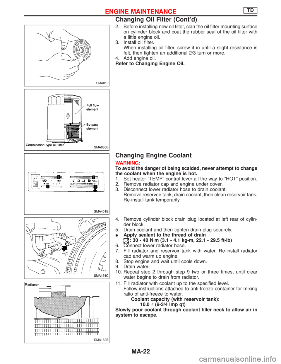
2. Before installing new oil filter, clan the oil filter mounting surface
on cylinder block and coat the rubber seal of the oil filter with
a little engine oil.
3. Install oil filter.
When installing oil filter, screw it in until a slight resistance is
felt, then tighten an additional 2/3 turn or more.
4. Add engine oil.
Refer to Changing Engine Oil.
Changing Engine Coolant
WARNING:
To avoid the danger of being scalded, never attempt to change
the coolant when the engine is hot.
1. Set heater ªTEMPº control lever all the way to ªHOTº position.
2. Remove radiator cap and engine under cover.
3. Disconnect lower radiator hose to drain coolant.
Remove reservoir tank, drain coolant, then clean reservoir tank.
Re-install tank temporarily.
4. Remove cylinder block drain plug located at left rear of cylin-
der block.
5. Drain coolant and then tighten drain plug securely.
IApply sealant to the thread of drain
:30-40N×m (3.1 - 4.1 kg-m, 22.1 - 29.5 ft-lb)
6. Connect lower radiator hose.
7. Fill radiator and reservoir tank with water. Re-install radiator
cap and warm up engine.
8. Stop engine and wait until cools down.
9. Drain water.
10. Repeat step 2 through step 9 two or three times, until clear
water begins to drain from radiator.
11. Fill radiator with coolant up to the specified level.
Follow instructions attached to anti-freeze container for mixing
ratio of anti-freeze to water.
Coolant capacity (with reservoir tank):
10.0(8-3/4 Imp qt)
Slowly pour coolant through coolant filler neck to allow air in
system to escape.
SMA010
SMA860B
SMA401B
SMA164C
SMA182B
ENGINE MAINTENANCETD
Changing Oil Filter (Cont'd)
MA-22
Page 1485 of 1767
Checking Idle Speed
Preparation
1. Make sure that injection timing is correct.
2. Make sure that injection nozzle are in good condition.
3. Make sure that the following parts are in good condition.
IAir cleaner clogging
IGlow system
IEngine oil and coolant levels
IValve clearance
IAir intake system (Oil filler cap, oil level gauge, etc.)
4. Set shift lever in ªNeutralº position. Engage parking brake and
lock both front and rear wheels with wheel chocks.
5. Turn off air conditioner, lights and accessories.
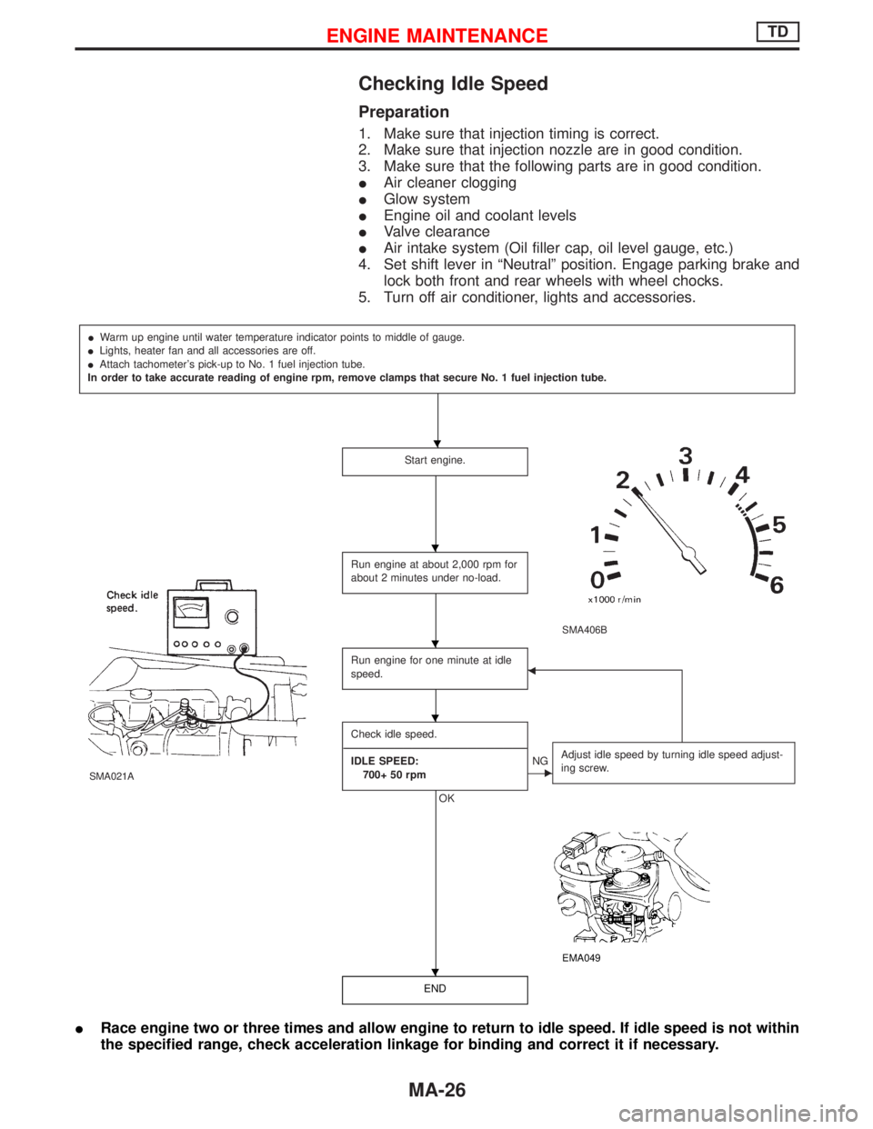
IWarm up engine until water temperature indicator points to middle of gauge.
ILights, heater fan and all accessories are off.
IAttach tachometer's pick-up to No. 1 fuel injection tube.
In order to take accurate reading of engine rpm, remove clamps that secure No. 1 fuel injection tube.
Start engine.
SMA406B
SMA021A
Run engine at about 2,000 rpm for
about 2 minutes under no-load.
Run engine for one minute at idle
speed.F
Check idle speed.
----------------------------------------------------------------------------------------------------------------------------------------------------------------------------------------------------------------------------------
IDLE SPEED:
700+ 50 rpm
OK
ENGAdjust idle speed by turning idle speed adjust-
ing screw.
EMA049
END
IRace engine two or three times and allow engine to return to idle speed. If idle speed is not within
the specified range, check acceleration linkage for binding and correct it if necessary.
H
H
H
H
H
ENGINE MAINTENANCETD
MA-26
Page 1490 of 1767
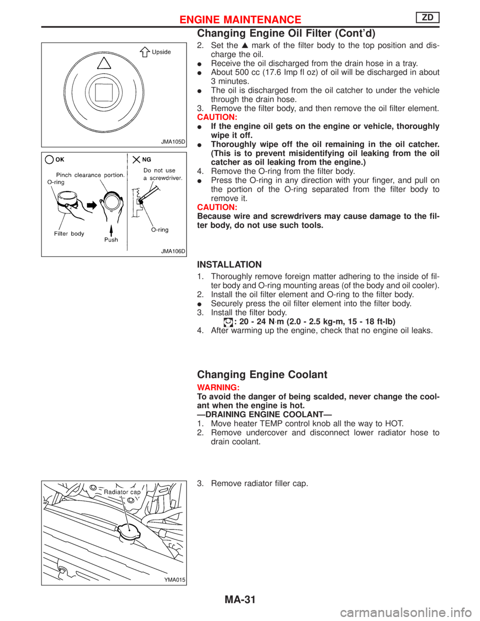
2. Set theGmark of the filter body to the top position and dis-
charge the oil.
IReceive the oil discharged from the drain hose in a tray.
IAbout 500 cc (17.6 Imp fl oz) of oil will be discharged in about
3 minutes.
IThe oil is discharged from the oil catcher to under the vehicle
through the drain hose.
3. Remove the filter body, and then remove the oil filter element.
CAUTION:
IIf the engine oil gets on the engine or vehicle, thoroughly
wipe it off.
IThoroughly wipe off the oil remaining in the oil catcher.
(This is to prevent misidentifying oil leaking from the oil
catcher as oil leaking from the engine.)
4. Remove the O-ring from the filter body.
IPress the O-ring in any direction with your finger, and pull on
the portion of the O-ring separated from the filter body to
remove it.
CAUTION:
Because wire and screwdrivers may cause damage to the fil-
ter body, do not use such tools.
INSTALLATION
1. Thoroughly remove foreign matter adhering to the inside of fil-
ter body and O-ring mounting areas (of the body and oil cooler).
2. Install the oil filter element and O-ring to the filter body.
ISecurely press the oil filter element into the filter body.
3. Install the filter body.
:20-24N×m (2.0 - 2.5 kg-m, 15 - 18 ft-lb)
4. After warming up the engine, check that no engine oil leaks.
Changing Engine Coolant
WARNING:
To avoid the danger of being scalded, never change the cool-
ant when the engine is hot.
ÐDRAINING ENGINE COOLANTÐ
1. Move heater TEMP control knob all the way to HOT.
2. Remove undercover and disconnect lower radiator hose to
drain coolant.
3. Remove radiator filler cap.
JMA105D
JMA106D
YMA015
ENGINE MAINTENANCEZD
Changing Engine Oil Filter (Cont'd)
MA-31