manual transmission NISSAN TERRANO 2002 Service User Guide
[x] Cancel search | Manufacturer: NISSAN, Model Year: 2002, Model line: TERRANO, Model: NISSAN TERRANO 2002Pages: 1767, PDF Size: 41.51 MB
Page 1323 of 1767
1.A QUICK REFERENCE INDEX, a black tab (e.g.) is provided on the first page. You can quickly find
the first page of each section by mating it to the section's black tab.
2.THE CONTENTSare listed on the first page of each section.
3.THE TITLEis indicated on the upper portion of each page and shows the part or system.
4.THE PAGE NUMBERof each section consists of two letters which designate the particular section and a
number (e.g. ªBR-5º).
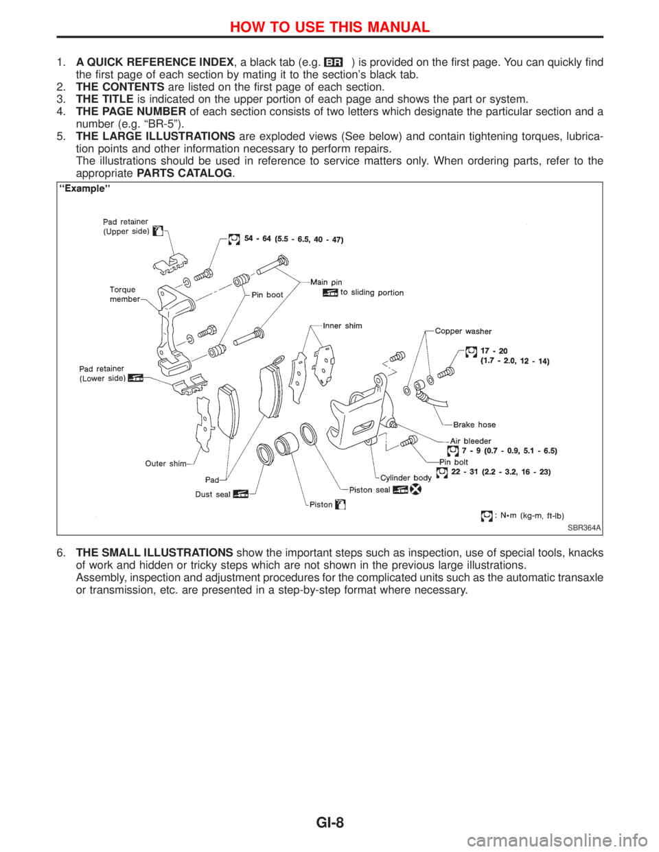
5.THE LARGE ILLUSTRATIONSare exploded views (See below) and contain tightening torques, lubrica-
tion points and other information necessary to perform repairs.
The illustrations should be used in reference to service matters only. When ordering parts, refer to the
appropriatePARTS CATALOG.
6.THE SMALL ILLUSTRATIONSshow the important steps such as inspection, use of special tools, knacks
of work and hidden or tricky steps which are not shown in the previous large illustrations.
Assembly, inspection and adjustment procedures for the complicated units such as the automatic transaxle
or transmission, etc. are presented in a step-by-step format where necessary.
SBR364A
HOW TO USE THIS MANUAL
GI-8
Page 1324 of 1767
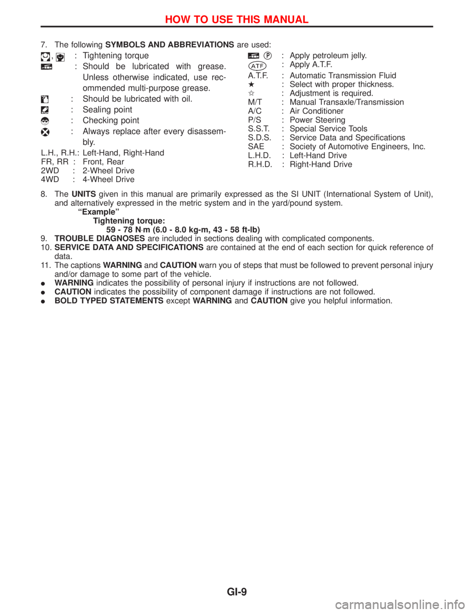
7. The followingSYMBOLS AND ABBREVIATIONSare used:
,: Tightening torque
: Should be lubricated with grease.
Unless otherwise indicated, use rec-
ommended multi-purpose grease.
: Should be lubricated with oil.
: Sealing point
: Checking point
: Always replace after every disassem-
bly.
L.H., R.H.: Left-Hand, Right-Hand
FR, RR : Front, Rear
2WD : 2-Wheel Drive
4WD : 4-Wheel Drive
qP: Apply petroleum jelly.
: Apply A.T.F.
A.T.F. : Automatic Transmission Fluid
H: Select with proper thickness.
I: Adjustment is required.
M/T : Manual Transaxle/Transmission
A/C : Air Conditioner
P/S : Power Steering
S.S.T. : Special Service Tools
S.D.S. : Service Data and Specifications
SAE : Society of Automotive Engineers, Inc.
L.H.D. : Left-Hand Drive
R.H.D. : Right-Hand Drive
8. TheUNITSgiven in this manual are primarily expressed as the SI UNIT (International System of Unit),
and alternatively expressed in the metric system and in the yard/pound system.
ªExampleº
Tightening torque:
59-78N×m (6.0 - 8.0 kg-m, 43 - 58 ft-lb)
9.TROUBLE DIAGNOSESare included in sections dealing with complicated components.
10.SERVICE DATA AND SPECIFICATIONSare contained at the end of each section for quick reference of
data.
11. The captionsWARNINGandCAUTIONwarn you of steps that must be followed to prevent personal injury
and/or damage to some part of the vehicle.
IWARNINGindicates the possibility of personal injury if instructions are not followed.
ICAUTIONindicates the possibility of component damage if instructions are not followed.
IBOLD TYPED STATEMENTSexceptWARNINGandCAUTIONgive you helpful information.
HOW TO USE THIS MANUAL
GI-9
Page 1337 of 1767
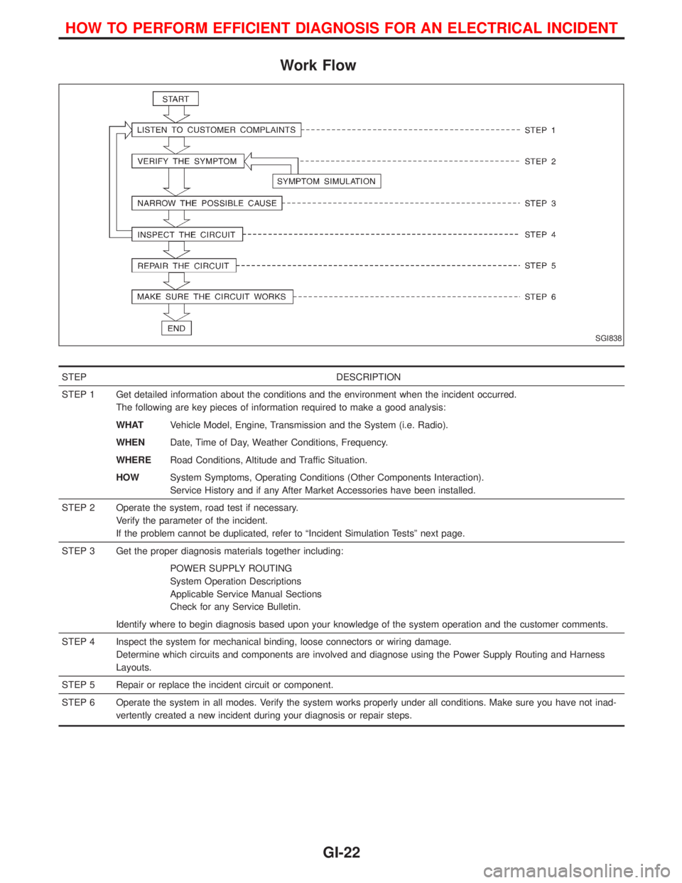
Work Flow
STEP DESCRIPTION
STEP 1 Get detailed information about the conditions and the environment when the incident occurred.
The following are key pieces of information required to make a good analysis:
WHATVehicle Model, Engine, Transmission and the System (i.e. Radio).
WHENDate, Time of Day, Weather Conditions, Frequency.
WHERERoad Conditions, Altitude and Traffic Situation.
HOWSystem Symptoms, Operating Conditions (Other Components Interaction).
Service History and if any After Market Accessories have been installed.
STEP 2 Operate the system, road test if necessary.
Verify the parameter of the incident.
If the problem cannot be duplicated, refer to ªIncident Simulation Testsº next page.
STEP 3 Get the proper diagnosis materials together including:
POWER SUPPLY ROUTING
System Operation Descriptions
Applicable Service Manual Sections
Check for any Service Bulletin.
Identify where to begin diagnosis based upon your knowledge of the system operation and the customer comments.
STEP 4 Inspect the system for mechanical binding, loose connectors or wiring damage.
Determine which circuits and components are involved and diagnose using the Power Supply Routing and Harness
Layouts.
STEP 5 Repair or replace the incident circuit or component.
STEP 6 Operate the system in all modes. Verify the system works properly under all conditions. Make sure you have not inad-
vertently created a new incident during your diagnosis or repair steps.
SGI838
HOW TO PERFORM EFFICIENT DIAGNOSIS FOR AN ELECTRICAL INCIDENT
GI-22
Page 1343 of 1767
Model Variation
Body Grade Engine Transmission Group A (RHD)Group B (South)
Group C (Cen-
tral)Group D (North)
H/TSE
ªLuxury/
EleganceºTD27Ti FS5R30A KVPNRVF-UEC KVPNLVF-UGC KVPNLVF-USC
ZD30ETiFS5R30A KWSNRVF-UEC KWSNLVF-UGC KWSNLVF-USC
RE4R01A KWSNRVA-UEC KWSNLVA-UGC KWSNLVA-USC
SR
ªSportºTD27Ti FS5R30A KVPNRUF-UEC KVPNLUF-UGC KVPNLUF-USC
ZD30ETiFS5R30A KWSNRUF-UEC KWSNLUF-UGC KWSNLUF-USC
RE4R01A KWSNRUA-UEC KWSNLUA-UGC KWSNLUA-USC
S ªComfortº TD27Ti FS5R30A KVPNRQF-UEC KVPNLQF-UGC KVPNLQF-USC
WagonSE
ªLuxury/
EleganceºTD27Ti FS5R30A TVPURVF-UEC TVPULVF-UGC TVPULVF-USC
ZD30ETiFS5R30A TWSURVF-UEC TWSULVF-UGC TWSULVF-USC
RE4R01A TWSURVA-UEC TWSULVA-UGC TWSULVA-USC
SR
ªSportºTD27Ti FS5R30A TVPURUF-UEC TVPULUF-UGC TVPULUF-USC
ZD30ETiFS5R30A TWSURUF-UEC TWSULUF-UGC TWSULUF-USC
RE4R01A TWSURUA-UEC TWSULUA-UGC TWSULUA-USC
S ªComfortº TD27Ti FS5R30A TVPURQF-UEC TVPULQF-UGC TVPULQF-USC
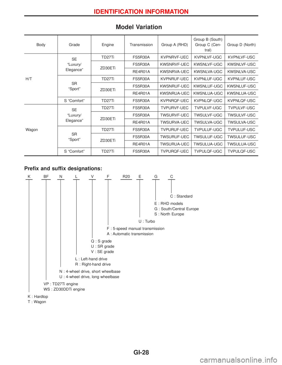
Prefix and suffix designations:
KBFNLVFR20EGC
C : Standard
E : RHD models
G : South/Central Europe
S : North Europe
U : Turbo
F : 5-speed manual transmission
A : Automatic transmission
Q : S grade
U : SR grade
V : SE grade
L : Left-hand drive
R : Right-hand drive
N : 4-wheel drive, short wheelbase
U : 4-wheel drive, long wheelbase
VP : TD27Ti engine
WS : ZD30DDTi engine
K : Hardtop
T : Wagon
IDENTIFICATION INFORMATION
GI-28
Page 1345 of 1767
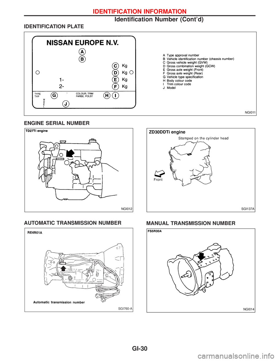
IDENTIFICATION PLATE
ENGINE SERIAL NUMBER
AUTOMATIC TRANSMISSION NUMBER
MANUAL TRANSMISSION NUMBER
NGI011
NGI012SGI137A
SGI760-ANGI014
IDENTIFICATION INFORMATION
Identification Number (Cont'd)
GI-30
Page 1419 of 1767
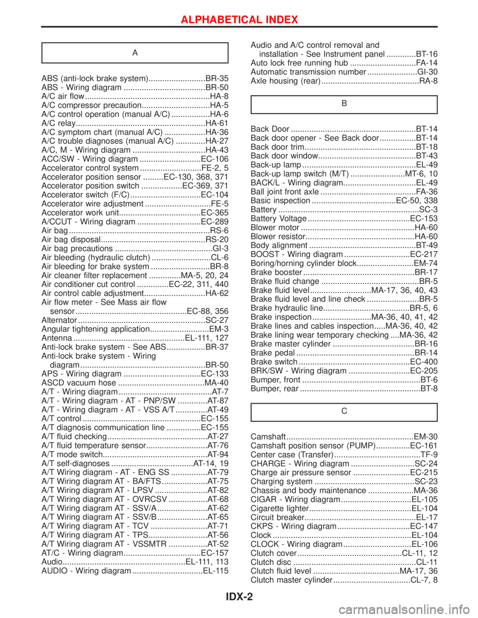
A
ABS (anti-lock brake system).........................BR-35
ABS - Wiring diagram ....................................BR-50
A/C air flow .......................................................HA-8
A/C compressor precaution..............................HA-5
A/C control operation (manual A/C) .................HA-6
A/C relay.........................................................HA-61
A/C symptom chart (manual A/C) ..................HA-36
A/C trouble diagnoses (manual A/C) .............HA-27
A/C, M - Wiring diagram ................................HA-43
ACC/SW - Wiring diagram ...........................EC-106
Accelerator control system ...........................FE-2, 5
Accelerator position sensor .........EC-130, 368, 371
Accelerator position switch ..................EC-369, 371
Accelerator switch (F/C) ...............................EC-104
Accelerator wire adjustment .............................FE-5
Accelerator work unit....................................EC-365
A/CCUT - Wiring diagram ............................EC-289
Air bag ..............................................................RS-6
Air bag disposal..............................................RS-20
Air bag precautions ...........................................GI-3
Air bleeding (hydraulic clutch) ..........................CL-6
Air bleeding for brake system ..........................BR-8
Air cleaner filter replacement ..............MA-5, 20, 24
Air conditioner cut control ..............EC-22, 311, 440
Air control cable adjustment...........................HA-62
Air flow meter - See Mass air flow
sensor .................................................EC-88, 356
Alternator ........................................................SC-27
Angular tightening application..........................EM-3
Antenna .................................................EL-111, 127
Anti-lock brake system - See ABS .................BR-37
Anti-lock brake system - Wiring
diagram .......................................................BR-50
APS - Wiring diagram ..................................EC-133
ASCD vacuum hose ......................................MA-40
A/T - Wiring diagram .........................................AT-7
A/T - Wiring diagram - AT - PNP/SW .............AT-87
A/T - Wiring diagram - AT - VSS A/T ..............AT-49
A/T control ....................................................EC-155
A/T diagnosis communication line ...............EC-155
A/T fluid checking ............................................AT-27
A/T fluid temperature sensor...........................AT-76
A/T mode switch..............................................AT-94
A/T self-diagnoses ....................................AT-14, 19
A/T Wiring diagram - AT - ENG SS ................AT-79
A/T Wiring diagram AT - BA/FTS ....................AT-75
A/T Wiring diagram AT - LPSV .......................AT-82
A/T Wiring diagram AT - OVRCSV .................AT-68
A/T Wiring diagram AT - SSV/A ......................AT-62
A/T Wiring diagram AT - SSV/B ......................AT-65
A/T Wiring diagram AT - TCV .........................AT-71
A/T Wiring diagram AT - TPS..........................AT-56
A/T Wiring diagram AT - VSSMTR .................AT-52
AT/C - Wiring diagram..................................EC-157
Audio......................................................EL-111, 113
AUDIO - Wiring diagram ...............................EL-115Audio and A/C control removal and
installation - See Instrument panel .............BT-16
Auto lock free running hub .............................FA-14
Automatic transmission number ......................GI-30
Axle housing (rear) ...........................................RA-8
B
Back Door .......................................................BT-14
Back door opener - See Back door ................BT-14
Back door trim.................................................BT-18
Back door window...........................................BT-43
Back-up lamp ..................................................EL-49
Back-up lamp switch (M/T) ........................MT-6, 10
BACK/L - Wiring diagram................................EL-49
Ball joint front axle ..........................................FA-36
Basic inspection .....................................EC-50, 338
Battery ..............................................................SC-3
Battery Voltage .............................................EC-153
Blower motor ..................................................HA-60
Blower resistor................................................HA-60
Body alignment ...............................................BT-49
BOOST - Wiring diagram .............................EC-217
Boring/horning cylinder block.........................EM-74
Brake booster .................................................BR-17
Brake fluid change ...........................................BR-5
Brake fluid level ...........................MA-17, 36, 40, 43
Brake fluid level and line check .......................BR-5
Brake hydraulic line......................................BR-5, 6
Brake inspection ..........................MA-36, 40, 41, 42
Brake lines and cables inspection.....MA-36, 40, 42
Brake lining wear temporary checking ....MA-36, 42
Brake master cylinder ....................................BR-16
Brake pedal ....................................................BR-14
Brake switch .................................................EC-400
BRK/SW - Wiring diagram ...........................EC-205
Bumper, front ....................................................BT-6
Bumper, rear .....................................................BT-8
C
Camshaft ........................................................EM-30
Camshaft position sensor (PUMP)...............EC-161
Center case (Transfer) ......................................TF-9
CHARGE - Wiring diagram ............................SC-24
Charge air pressure sensor .........................EC-215
Charging system ............................................SC-23
Chassis and body maintenance ....................MA-36
CIGAR - Wiring diagram ...............................EL-105
Cigarette lighter.............................................EL-104
Circuit breaker.................................................EL-17
CKPS - Wiring diagram ................................EC-147
Clock .............................................................EL-104
CLOCK - Wiring diagram ..............................EL-106
Clutch cover ..............................................CL-11, 12
Clutch disc ......................................................CL-11
Clutch fluid level ......................................MA-17, 36
Clutch master cylinder ..................................CL-7, 8
ALPHABETICAL INDEX
IDX-2
Page 1422 of 1767
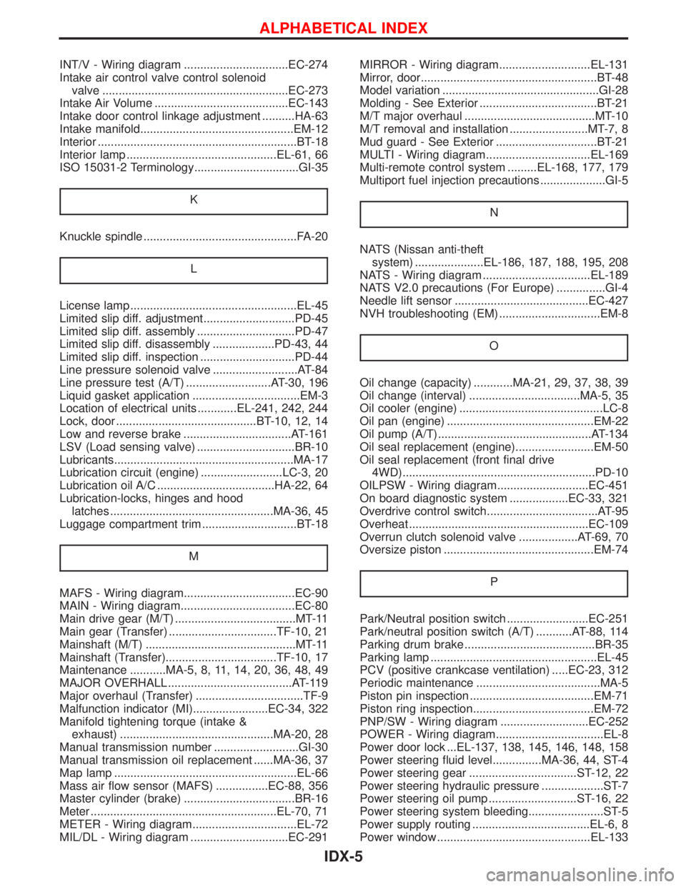
INT/V - Wiring diagram ................................EC-274
Intake air control valve control solenoid
valve .........................................................EC-273
Intake Air Volume .........................................EC-143
Intake door control linkage adjustment ..........HA-63
Intake manifold...............................................EM-12
Interior .............................................................BT-18
Interior lamp ..............................................EL-61, 66
ISO 15031-2 Terminology................................GI-35
K
Knuckle spindle ...............................................FA-20
L
License lamp ...................................................EL-45
Limited slip diff. adjustment............................PD-45
Limited slip diff. assembly ..............................PD-47
Limited slip diff. disassembly ...................PD-43, 44
Limited slip diff. inspection .............................PD-44
Line pressure solenoid valve ..........................AT-84
Line pressure test (A/T) ..........................AT-30, 196
Liquid gasket application .................................EM-3
Location of electrical units ............EL-241, 242, 244
Lock, door ...........................................BT-10, 12, 14
Low and reverse brake .................................AT-161
LSV (Load sensing valve) ..............................BR-10
Lubricants.......................................................MA-17
Lubrication circuit (engine) .........................LC-3, 20
Lubrication oil A/C ....................................HA-22, 64
Lubrication-locks, hinges and hood
latches ..................................................MA-36, 45
Luggage compartment trim .............................BT-18
M
MAFS - Wiring diagram..................................EC-90
MAIN - Wiring diagram...................................EC-80
Main drive gear (M/T) .....................................MT-11
Main gear (Transfer) .................................TF-10, 21
Mainshaft (M/T) ..............................................MT-11
Mainshaft (Transfer)..................................TF-10, 17
Maintenance ...........MA-5, 8, 11, 14, 20, 36, 48, 49
MAJOR OVERHALL ......................................AT-119
Major overhaul (Transfer) .................................TF-9
Malfunction indicator (MI).......................EC-34, 322
Manifold tightening torque (intake &
exhaust) ...............................................MA-20, 28
Manual transmission number ..........................GI-30
Manual transmission oil replacement ......MA-36, 37
Map lamp ........................................................EL-66
Mass air flow sensor (MAFS) ................EC-88, 356
Master cylinder (brake) ..................................BR-16
Meter .........................................................EL-70, 71
METER - Wiring diagram................................EL-72
MIL/DL - Wiring diagram ..............................EC-291MIRROR - Wiring diagram............................EL-131
Mirror, door......................................................BT-48
Model variation ................................................GI-28
Molding - See Exterior ....................................BT-21
M/T major overhaul ........................................MT-10
M/T removal and installation ........................MT-7, 8
Mud guard - See Exterior ...............................BT-21
MULTI - Wiring diagram................................EL-169
Multi-remote control system .........EL-168, 177, 179
Multiport fuel injection precautions ....................GI-5
N
NATS (Nissan anti-theft
system) .....................EL-186, 187, 188, 195, 208
NATS - Wiring diagram .................................EL-189
NATS V2.0 precautions (For Europe) ...............GI-4
Needle lift sensor .........................................EC-427
NVH troubleshooting (EM) ...............................EM-8
O
Oil change (capacity) ............MA-21, 29, 37, 38, 39
Oil change (interval) ..................................MA-5, 35
Oil cooler (engine) ............................................LC-8
Oil pan (engine) .............................................EM-22
Oil pump (A/T)...............................................AT-134
Oil seal replacement (engine)........................EM-50
Oil seal replacement (front final drive
4WD)...........................................................PD-10
OILPSW - Wiring diagram............................EC-451
On board diagnostic system ..................EC-33, 321
Overdrive control switch..................................AT-95
Overheat .......................................................EC-109
Overrun clutch solenoid valve ..................AT-69, 70
Oversize piston ..............................................EM-74
P
Park/Neutral position switch .........................EC-251
Park/neutral position switch (A/T) ...........AT-88, 114
Parking drum brake ........................................BR-35
Parking lamp ...................................................EL-45
PCV (positive crankcase ventilation) .....EC-23, 312
Periodic maintenance ......................................MA-5
Piston pin inspection ......................................EM-71
Piston ring inspection.....................................EM-72
PNP/SW - Wiring diagram ...........................EC-252
POWER - Wiring diagram.................................EL-8
Power door lock ...EL-137, 138, 145, 146, 148, 158
Power steering fluid level...............MA-36, 44, ST-4
Power steering gear .................................ST-12, 22
Power steering hydraulic pressure ...................ST-7
Power steering oil pump ...........................ST-16, 22
Power steering system bleeding.......................ST-5
Power supply routing ....................................EL-6, 8
Power window ...............................................EL-133
ALPHABETICAL INDEX
IDX-5
Page 1462 of 1767
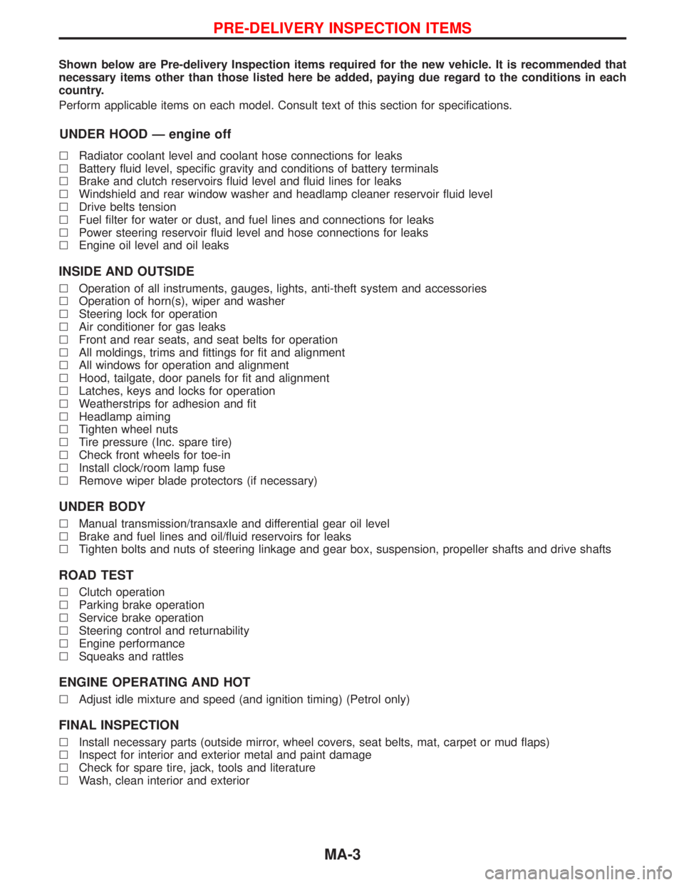
Shown below are Pre-delivery Inspection items required for the new vehicle. It is recommended that
necessary items other than those listed here be added, paying due regard to the conditions in each
country.
Perform applicable items on each model. Consult text of this section for specifications.
UNDER HOOD Ð engine off
lRadiator coolant level and coolant hose connections for leaks
lBattery fluid level, specific gravity and conditions of battery terminals
lBrake and clutch reservoirs fluid level and fluid lines for leaks
lWindshield and rear window washer and headlamp cleaner reservoir fluid level
lDrive belts tension
lFuel filter for water or dust, and fuel lines and connections for leaks
lPower steering reservoir fluid level and hose connections for leaks
lEngine oil level and oil leaks
INSIDE AND OUTSIDE
lOperation of all instruments, gauges, lights, anti-theft system and accessories
lOperation of horn(s), wiper and washer
lSteering lock for operation
lAir conditioner for gas leaks
lFront and rear seats, and seat belts for operation
lAll moldings, trims and fittings for fit and alignment
lAll windows for operation and alignment
lHood, tailgate, door panels for fit and alignment
lLatches, keys and locks for operation
lWeatherstrips for adhesion and fit
lHeadlamp aiming
lTighten wheel nuts
lTire pressure (Inc. spare tire)
lCheck front wheels for toe-in
lInstall clock/room lamp fuse
lRemove wiper blade protectors (if necessary)
UNDER BODY
lManual transmission/transaxle and differential gear oil level
lBrake and fuel lines and oil/fluid reservoirs for leaks
lTighten bolts and nuts of steering linkage and gear box, suspension, propeller shafts and drive shafts
ROAD TEST
lClutch operation
lParking brake operation
lService brake operation
lSteering control and returnability
lEngine performance
lSqueaks and rattles
ENGINE OPERATING AND HOT
lAdjust idle mixture and speed (and ignition timing) (Petrol only)
FINAL INSPECTION
lInstall necessary parts (outside mirror, wheel covers, seat belts, mat, carpet or mud flaps)
lInspect for interior and exterior metal and paint damage
lCheck for spare tire, jack, tools and literature
lWash, clean interior and exterior
PRE-DELIVERY INSPECTION ITEMS
MA-3
Page 1466 of 1767
![NISSAN TERRANO 2002 Service User Guide Chassis and Body Maintenance
Abbreviations: R = Replace I = Inspect. Correct or replace if necessary L = Lubricate T = Tighten
[ ] = At the specified mileage only
MAINTENANCE OPERATION MAINTENANCE INT](/img/5/57393/w960_57393-1465.png "NISSAN TERRANO 2002 Service User Guide Chassis and Body Maintenance
Abbreviations: R = Replace I = Inspect. Correct or replace if necessary L = Lubricate T = Tighten
[ ] = At the specified mileage only
MAINTENANCE OPERATION MAINTENANCE INT")
Chassis and Body Maintenance
Abbreviations: R = Replace I = Inspect. Correct or replace if necessary L = Lubricate T = Tighten
[ ] = At the specified mileage only
MAINTENANCE OPERATION MAINTENANCE INTERVAL
Refer-
ence
page Perform on a kilometer basis, but on
a semi-annual basis when driving
less than 20,000 km (12,000 miles)
per year.km x 1,000 10 20 30 40 50 60 70 80 90 100 110 120
(miles x 1,000) (6) (12) (18) (24) (30) (36) (42) (48) (54) (60) (66) (72)
Months 6 12 18 24 30 36 42 48 54 50 66 72
Underhood and under vehicle
Headlamp aimingIIIIIIEL-37
Wheel alignment (if necessary, rotate & balance wheels)IIIIIIMA-43
Brake pads, discs & other components*IIIIIIMA-40
Brake linings, drums & other components*IIIIIIMA-41
Foot brake, parking brake & clutch (for free play, stroke &
operation)IIIIIIMA-42
Brake booster vacuum hoses, connections, check valve I I I MA-40
Brake & clutch, systems and fluid (for level and leaks)IIIIIIMA-36/
MA-40
Brake fluid*R R R MA-43
Power steering fluid and lines (for level and leaks)IIIIIIMA-44
Air bag system See NOTE (1)RS-15
Ventilation air filter*RRRRMA-44
Transfer and standard differential gear oil* I I R I I RMA-37/
MA-38
Manual transmission oil I I I [R] I I MA-36
LSD gear oil (for level and leaks)* I I R I I R MA-38
Steering gear & linkage, axle & suspension parts, propeller
shaft and exhaust system*IIIIIIMA-43/
FA-4/
RA-4/
MA-38/
MA-36
Greasing points of steering gear linkage,
propeller shaft and suspension*See NOTE (2)LLLLLLMA-44/
MA-38
Drive shafts*IIIIIIFA-13
Front wheel bearing grease*IRIRIRMA-39
Free running hub grease*IIIIIIMA-40
Body mounting bolts and nutsTTTTTTBT-48
Body corrosion See NOTE (3)MA-47
NOTE: (1) Inspect after 10 years, then every 2 years.
(2) The propeller shaft should be re-greased daily if it is immersed in water.
(3) Inspect once per year.
* Maintenance items with ª*º should be performed more frequently according to ªMaintenance under severe driving
conditionsº.
PERIODIC MAINTENANCE
Maintenance Schedule for Diesel Engine
Models (annual mileage < 30,000 km/year)
(Cont'd)
MA-7
Page 1469 of 1767
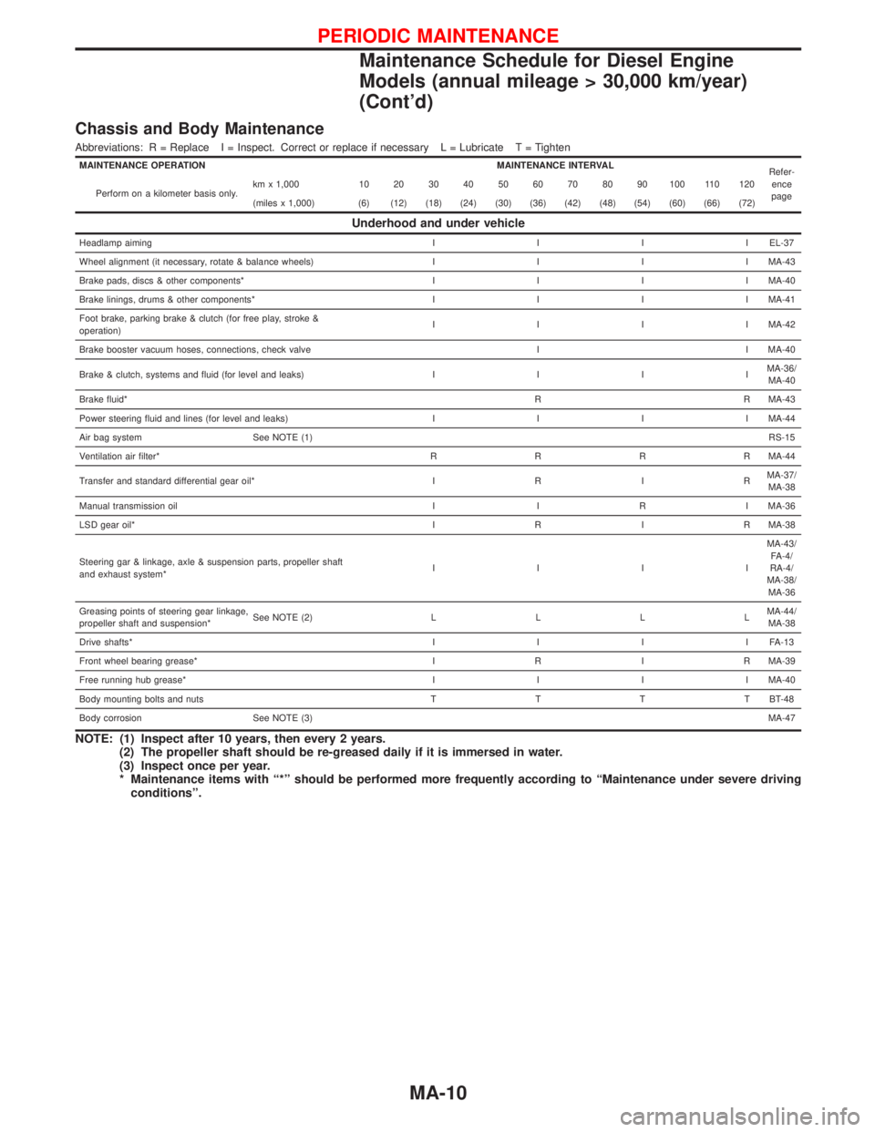
Chassis and Body Maintenance
Abbreviations: R = Replace I = Inspect. Correct or replace if necessary L = Lubricate T = Tighten
MAINTENANCE OPERATION MAINTENANCE INTERVAL
Refer-
ence
page Perform on a kilometer basis only.km x 1,000 10 20 30 40 50 60 70 80 90 100 110 120
(miles x 1,000) (6) (12) (18) (24) (30) (36) (42) (48) (54) (60) (66) (72)
Underhood and under vehicle
Headlamp aimingIIIIEL-37
Wheel alignment (it necessary, rotate & balance wheels)IIIIMA-43
Brake pads, discs & other components*IIIIMA-40
Brake linings, drums & other components*IIIIMA-41
Foot brake, parking brake & clutch (for free play, stroke &
operation)IIIIMA-42
Brake booster vacuum hoses, connections, check valve I I MA-40
Brake & clutch, systems and fluid (for level and leaks)IIIIMA-36/
MA-40
Brake fluid*R R MA-43
Power steering fluid and lines (for level and leaks)IIIIMA-44
Air bag system See NOTE (1)RS-15
Ventilation air filter*RRRRMA-44
Transfer and standard differential gear oil*IRIRMA-37/
MA-38
Manual transmission oil I I R I MA-36
LSD gear oil*IRIRMA-38
Steering gar & linkage, axle & suspension parts, propeller shaft
and exhaust system*IIIIMA-43/
FA-4/
RA-4/
MA-38/
MA-36
Greasing points of steering gear linkage,
propeller shaft and suspension*See NOTE (2)LLLLMA-44/
MA-38
Drive shafts*IIIIFA-13
Front wheel bearing grease*IRIRMA-39
Free running hub grease*IIIIMA-40
Body mounting bolts and nutsTTTTBT-48
Body corrosion See NOTE (3)MA-47
NOTE: (1) Inspect after 10 years, then every 2 years.
(2) The propeller shaft should be re-greased daily if it is immersed in water.
(3) Inspect once per year.
* Maintenance items with ª*º should be performed more frequently according to ªMaintenance under severe driving
conditionsº.
PERIODIC MAINTENANCE
Maintenance Schedule for Diesel Engine
Models (annual mileage > 30,000 km/year)
(Cont'd)
MA-10