wheel size NISSAN TERRANO 2002 Service Repair Manual
[x] Cancel search | Manufacturer: NISSAN, Model Year: 2002, Model line: TERRANO, Model: NISSAN TERRANO 2002Pages: 1767, PDF Size: 41.51 MB
Page 276 of 1767
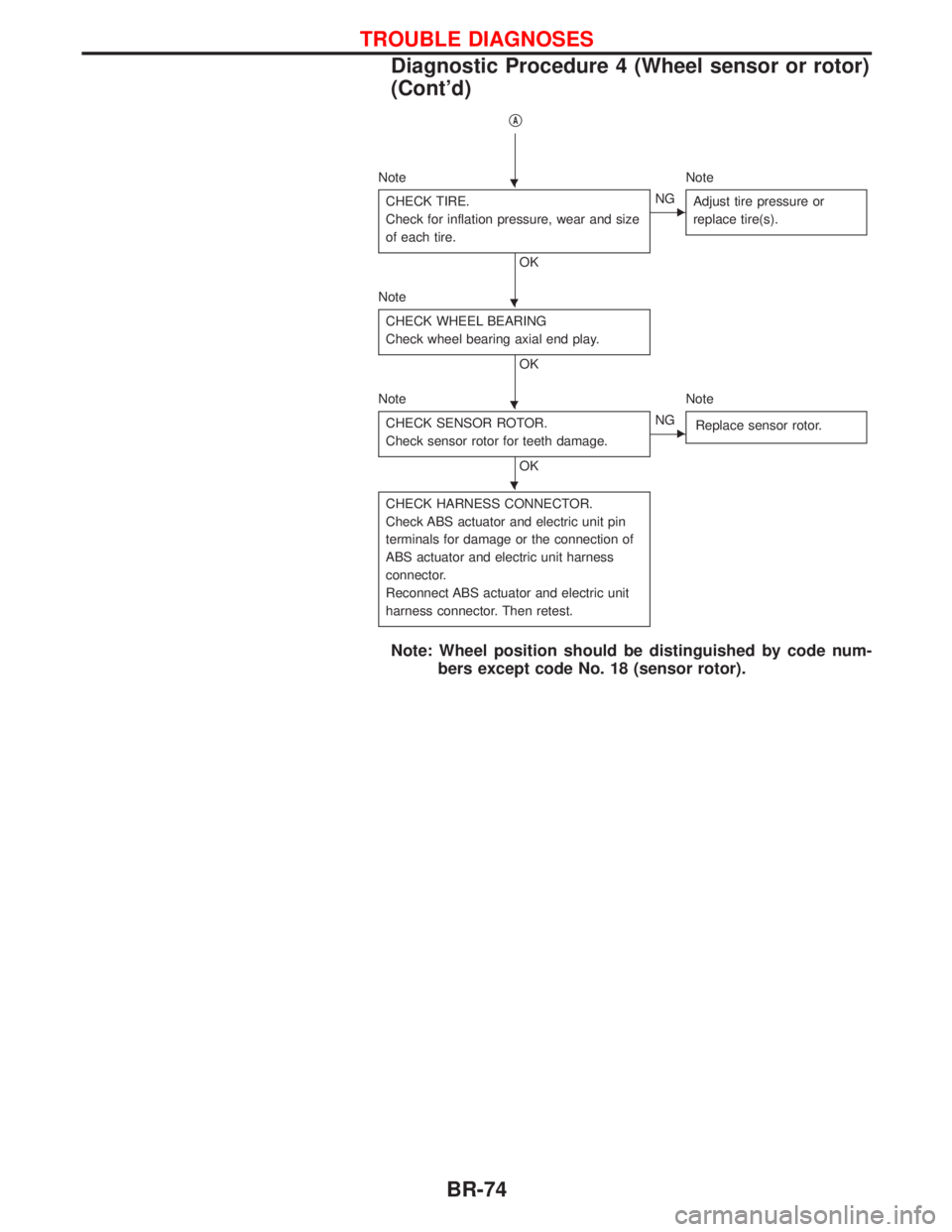
qA
Note Note
CHECK TIRE.
Check for inflation pressure, wear and size
of each tire.
OK
ENG
Adjust tire pressure or
replace tire(s).
Note
CHECK WHEEL BEARING
Check wheel bearing axial end play.
OK
Note Note
CHECK SENSOR ROTOR.
Check sensor rotor for teeth damage.
OK
ENG
Replace sensor rotor.
CHECK HARNESS CONNECTOR.
Check ABS actuator and electric unit pin
terminals for damage or the connection of
ABS actuator and electric unit harness
connector.
Reconnect ABS actuator and electric unit
harness connector. Then retest.
Note: Wheel position should be distinguished by code num-
bers except code No. 18 (sensor rotor).
H
H
H
H
TROUBLE DIAGNOSES
Diagnostic Procedure 4 (Wheel sensor or rotor)
(Cont'd)
BR-74
Page 1239 of 1767
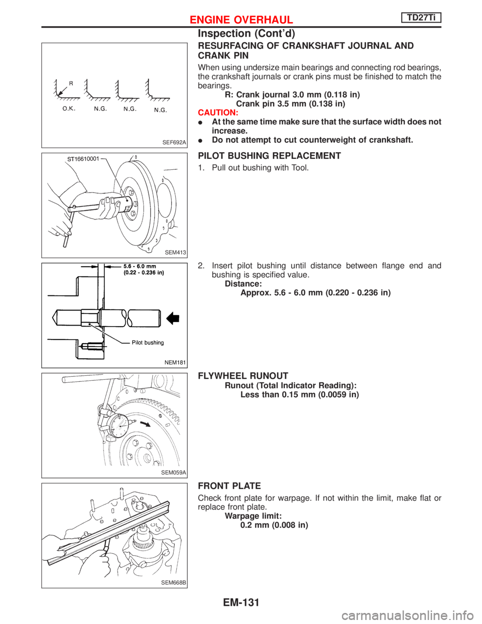
RESURFACING OF CRANKSHAFT JOURNAL AND
CRANK PIN
When using undersize main bearings and connecting rod bearings,
the crankshaft journals or crank pins must be finished to match the
bearings.
R: Crank journal 3.0 mm (0.118 in)
Crank pin 3.5 mm (0.138 in)
CAUTION:
IAt the same time make sure that the surface width does not
increase.
IDo not attempt to cut counterweight of crankshaft.
PILOT BUSHING REPLACEMENT
1. Pull out bushing with Tool.
2. Insert pilot bushing until distance between flange end and
bushing is specified value.
Distance:
Approx. 5.6 - 6.0 mm (0.220 - 0.236 in)
FLYWHEEL RUNOUT
Runout (Total Indicator Reading):
Less than 0.15 mm (0.0059 in)
FRONT PLATE
Check front plate for warpage. If not within the limit, make flat or
replace front plate.
Warpage limit:
0.2 mm (0.008 in)
SEF692A
SEM413
NEM181
SEM059A
SEM668B
ENGINE OVERHAULTD27Ti
Inspection (Cont'd)
EM-131
Page 1258 of 1767
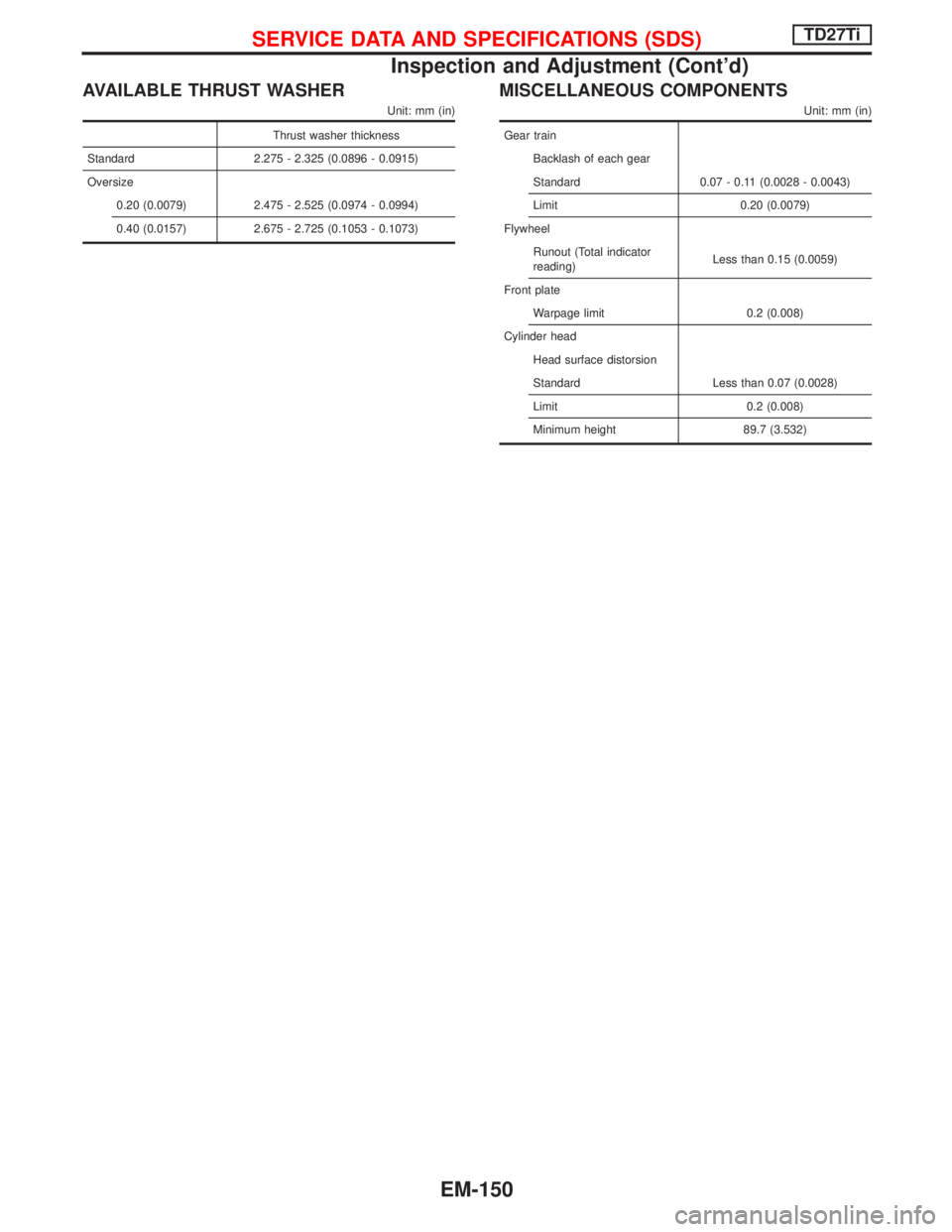
AVAILABLE THRUST WASHER
Unit: mm (in)
Thrust washer thickness
Standard 2.275 - 2.325 (0.0896 - 0.0915)
Oversize
0.20 (0.0079) 2.475 - 2.525 (0.0974 - 0.0994)
0.40 (0.0157) 2.675 - 2.725 (0.1053 - 0.1073)
MISCELLANEOUS COMPONENTS
Unit: mm (in)
Gear train
Backlash of each gear
Standard 0.07 - 0.11 (0.0028 - 0.0043)
Limit 0.20 (0.0079)
Flywheel
Runout (Total indicator
reading)Less than 0.15 (0.0059)
Front plate
Warpage limit 0.2 (0.008)
Cylinder head
Head surface distorsion
Standard Less than 0.07 (0.0028)
Limit 0.2 (0.008)
Minimum height 89.7 (3.532)
SERVICE DATA AND SPECIFICATIONS (SDS)TD27Ti
Inspection and Adjustment (Cont'd)
EM-150
Page 1346 of 1767
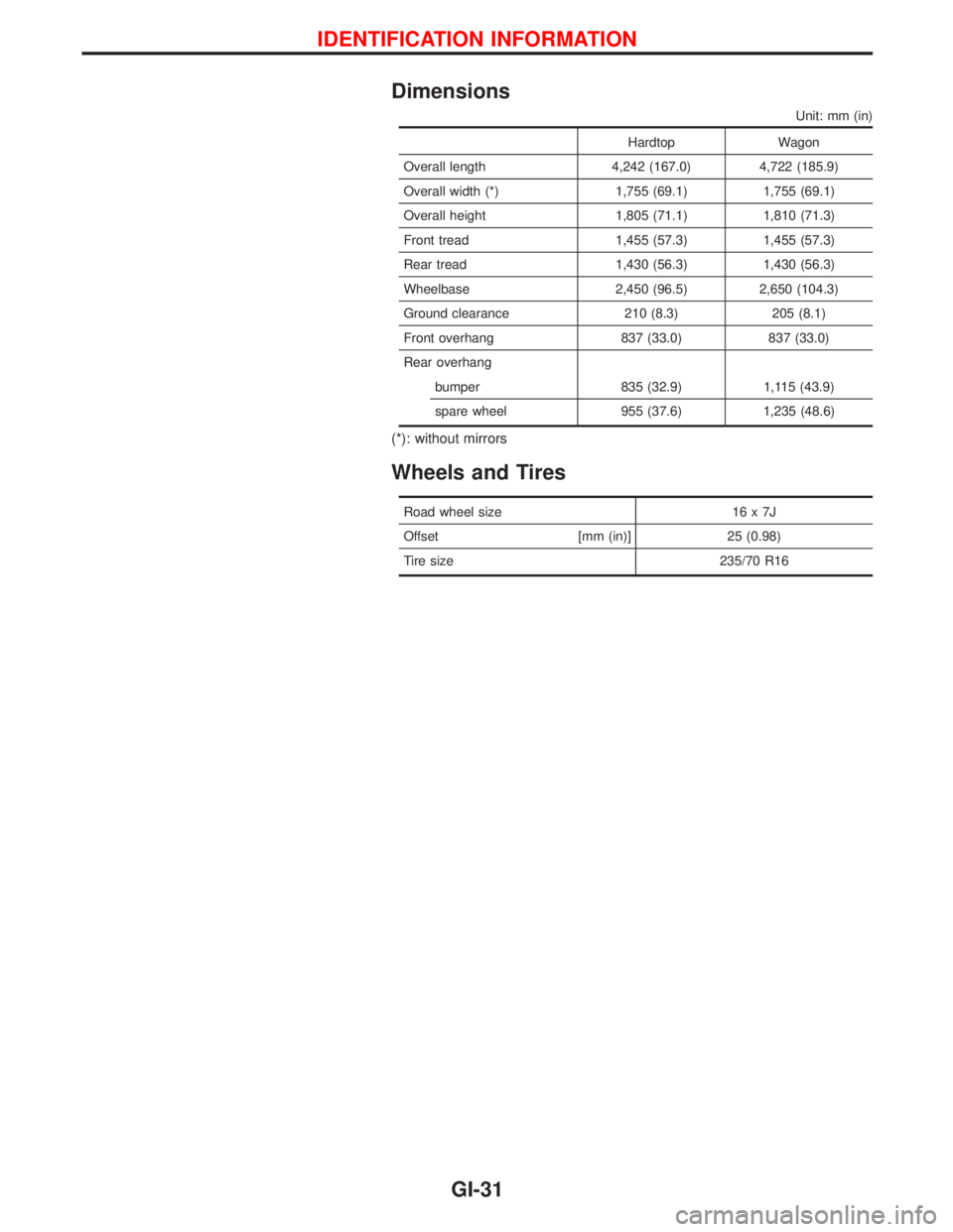
Dimensions
Unit: mm (in)
Hardtop Wagon
Overall length 4,242 (167.0) 4,722 (185.9)
Overall width (*) 1,755 (69.1) 1,755 (69.1)
Overall height 1,805 (71.1) 1,810 (71.3)
Front tread 1,455 (57.3) 1,455 (57.3)
Rear tread 1,430 (56.3) 1,430 (56.3)
Wheelbase 2,450 (96.5) 2,650 (104.3)
Ground clearance 210 (8.3) 205 (8.1)
Front overhang 837 (33.0) 837 (33.0)
Rear overhang
bumper 835 (32.9) 1,115 (43.9)
spare wheel 955 (37.6) 1,235 (48.6)
(*): without mirrors
Wheels and Tires
Road wheel size 16 x 7J
Offset [mm (in)] 25 (0.98)
Tire size 235/70 R16
IDENTIFICATION INFORMATION
GI-31
Page 1424 of 1767
TAIL/L - Wiring diagram ..................................EL-45
TCM circuit diagram ..........................................AT-7
TCM inspection table ......................................AT-46
TDC Pulse Signal .........................................EC-168
Temperature control cable and linkage
adjustment ..................................................HA-63
THEFT - Wiring diagram...............................EL-214
Theft warning system ...........EL-209, 210, 213, 230
Thermo control amp .................................HA-51, 61
Thermostat................................................LC-12, 31
Third (3rd) seat ...............................................BT-39
THLCNT - Wiring diagram ...........................EC-435
Three way catalyst precautions.........................GI-5
Throttle control solenoid valve .....................EC-435
Throttle position switch ...................................AT-60
Tie-rod .......................................................ST-19, 21
Tie-rod ball joints.............................................ST-20
Tightening torque of standard bolts.................GI-38
Time control system .....................EL-180, 182, 184
Timing chain ...................................................EM-26
Timing gear ....................................................EM-38
Tire rotation ....................................................MA-43
Tooth contact diff. .....................................PD-27, 52
Torque convertor clutch solenoid valve ..AT-72, 141
Torsion bar spring .......................................FA-4, 30
Tow truck towing ..............................................GI-33
Towing point.....................................................GI-34
Transaxle fluid replacement.....................MA-36, 37
Transfer case ..............................................TF-9, 12
Transfer fluid replacement (Part time
4WD model) .........................................MA-36, 37
Transfer oil replacement ..........................MA-36, 38
Transmission case (M/T)..........................MT-10, 14
TRANSMT - Wiring diagram ...........................EL-80
Tread-FR&RR (Dimensions)............................GI-25
Trim...............................................BT-18, 19, 20, 21
Trunk room trim...............................................BT-47
Turbocharger ..................................................EM-14
Turbocharger charge air cooler......................EM-11
Turbocharger precautions..................................GI-5
TURN - Wiring diagram ..................................EL-56
Turn signal lamp .......................................EL-55, 56
U
Under body .....................................................BT-53
Upper link (front susp.) ...................................FA-33
V
Vacuum hose (brake system) ........................BR-19Vacuum hose drawing (Engine
control)................................................EC-18, 304
Vacuum pump .............................EM-24, BR-23, 25
Valve clearance..............................................EM-35
Valve clearance adjustment.....................MA-20, 28
Valve guide ....................................................EM-59
Valve lifter ......................................................EM-32
Valve seat ......................................................EM-60
Valve spring ...................................................EM-61
Variable nozzle turbocharger control
solenoid valve ...........................................EC-281
Vehicle identification number...........................GI-29
Vehicle speed sensor (VSS) ..................EC-99, 397
Ventilator door control rod adjustment ...........HA-61
Viscosity number (SAE)...........................MA-17, 18
VNT - Wiring diagram ..................................EC-283
VSS - Wiring diagram ..................................EC-101
W
WARN - Wiring diagram ...........................EL-82, 93
Warning chime ..........................................EL-81, 93
Warning lamps ..........................................EL-81, 82
Washer, front ...................................................EL-94
Washer, rear....................................................EL-96
Water cock control rod adjustment ................HA-63
Water pump ..............................................LC-11, 29
Water temperature gauge ...............................EL-72
Weatherstrip - See Exterior ............................BT-21
Wheel alignment (front) ....................................FA-8
Wheel balance ...............................................MA-43
Wheel bearing (front axle) ................................FA-6
Wheel bearing (rear) ..................................RA-5, 16
Wheel hub (front) ........................................FA-4, 18
Wheel sensors (ABS)...............................BR-38, 42
Wheel size .......................................................GI-31
WINDOW - Wiring diagram ..........................EL-134
Window, back door .........................................BT-47
Window, door ..................................................BT-42
Window, rear side .....................................BT-42, 43
Window, side - See Rear side window ...........BT-43
Windshield.......................................................BT-42
WIP/R - Wiring diagram ..................................EL-96
WIPER - Wiring diagram ........................EL-94, 100
Wiper and washer.....................................EL-94, 98
Wiper, front......................................................EL-94
Wiper, rear ......................................................EL-96
Wiring Diagram (Cell code) list .....................EL-291
ALPHABETICAL INDEX
IDX-7
Page 1632 of 1767
IInstall driver air bag module to steering wheel to check fit or
alignment with the wheel.
ICheck steering wheel for excessive free play.
IInstall front passenger air bag module to instrument panel to
check fit or alignment with the instrument panel.
IInstall front side air bag module to seatback to check fit and
alignment with the seat.
3) Spiral cable
ICheck spiral cable for dents, cracks, or deformities.
ICheck connectors and protective tape for damage.
ICheck steering wheel for noise, binding or heavy operation.
4) Main harness, body harness, side air bag module sub-harness
ICheck connectors for poor connections, damage, and terminals
for deformities.
ICheck harnesses for binding, chafing or cut.
5) Front seat belt pre-tensioner
ICheck harness cover and connectors for damage, terminals for
deformities, and harness for binding.
ICheck belts for damage and anchors for loose mounting.
ICheck retractor for smooth operation.
IPerform self-diagnosis for seat belt pre-tensioner using ªAIR
BAGº warning lamp or CONSULT-II.
Refer to ªSRS Operation Checkº for details. (RS-36)
6) Side air bag (satellite) sensor
ICheck side air bag (satellite) sensor (including bracket portion)
for dents, cracks or deformities.
ICheck connectors for damage, and terminals for deformities.
CAUTION:
Replace previously used special bolts and ground bolt with
new ones.
Diagnosis Sensor Unit
REMOVAL AND INSTALLATION
CAUTION:
IBefore servicing SRS, turn the ignition switch off, discon-
nect both battery cables and wait at least 3 minutes.
IThe special bolts are coated with bonding agent while the
other bolt is for ground. Do not use old bolts after removal;
replace with new ones.
ICheck diagnosis sensor unit for proper installation.
ICheck diagnosis sensor unit to ensure it is free of
deformities, dents, cracks or rust. If they show any visible
signs of damage, replace them with new ones.
ICheck diagnosis sensor unit brackets to ensure they are
free of deformities or rust.
IReplace diagnosis sensor unit if it has been dropped or
sustained an impact.
IAfter replacement of diagnosis sensor unit, perform self-
diagnosis for SRS. Refer to ªSRS Operation Checkº for
details. (RS-36)
1. Disconnect driver, front passenger and front side air bag mod-
ule connectors. Also, disconnect front seat belt pre-tensioner
connector.
2. Remove console box. Refer to BT-22, ªINSTRUMENT PANEL
ASSEMBLYº.
3. Disconnect diagnosis sensor unit connector.
4. Remove ground bolt and also remove special bolts using the
TAMPER RESISTANT TORX (Size T50), from diagnosis sen-
sor unit.
Then remove the diagnosis sensor unit.
SUPPLEMENTAL RESTRAINT SYSTEM (SRS)
Maintenance Items (Cont'd)
RS-11
Page 1635 of 1767
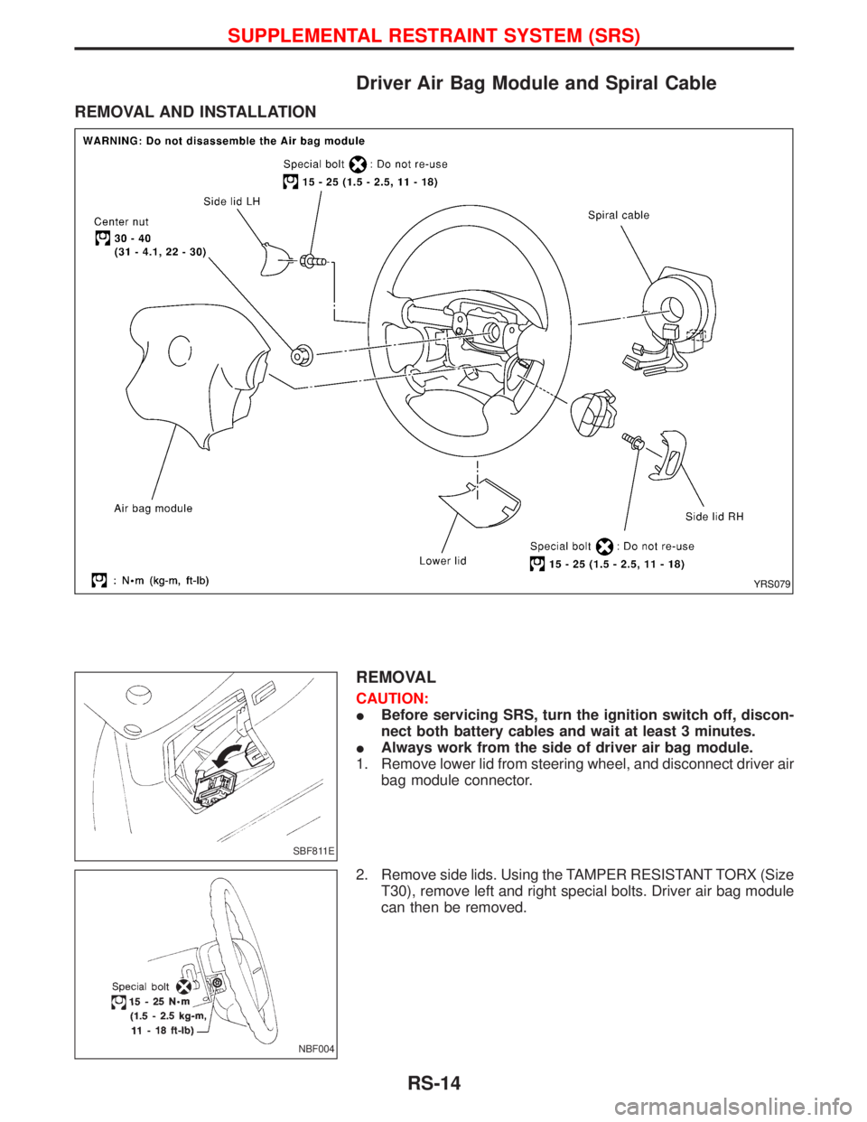
Driver Air Bag Module and Spiral Cable
REMOVAL AND INSTALLATION
REMOVAL
CAUTION:
IBefore servicing SRS, turn the ignition switch off, discon-
nect both battery cables and wait at least 3 minutes.
IAlways work from the side of driver air bag module.
1. Remove lower lid from steering wheel, and disconnect driver air
bag module connector.
2. Remove side lids. Using the TAMPER RESISTANT TORX (Size
T30), remove left and right special bolts. Driver air bag module
can then be removed.
YRS079
SBF811E
NBF004
SUPPLEMENTAL RESTRAINT SYSTEM (SRS)
RS-14