ignition NISSAN TERRANO 2002 Service Repair Manual
[x] Cancel search | Manufacturer: NISSAN, Model Year: 2002, Model line: TERRANO, Model: NISSAN TERRANO 2002Pages: 1767, PDF Size: 41.51 MB
Page 1673 of 1767
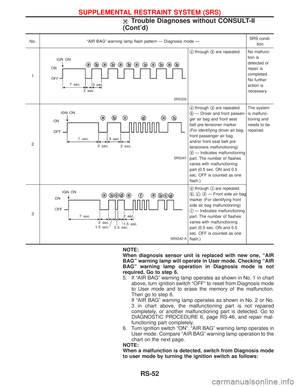
No. ªAIR BAGº warning lamp flash pattern Ð Diagnosis mode ÐSRS condi-
tion
1
SRS333
qathroughqbare repeated. No malfunc-
tion is
detected or
repair is
completed.
No further
action is
necessary.
2
SRS341
qathroughqdare repeated.
q
bÐ Driver and front passen-
ger air bag and front seat
belt pre-tensioner marker
(For identifying driver air bag,
front passenger air bag
and/or front seat belt pre-
tensioners malfunctioning)
q
dÐ Indicates malfunctioning
part. The number of flashes
varies with malfunctioning
part (0.5 sec. ON and 0.5
sec. OFF is counted as one
flash.)The system
is malfunc-
tioning and
needs to be
repaired.
3
SRS342-A
qathroughqfare repeated.
q
b,qc,qdÐ Front side air bag
marker (For identifying front
side air bag malfunctioning)
q
fÐ Indicates malfunctioning
part. The number of flashes
varies with malfunctioning
part (0.5 sec. ON and 0.5
sec. OFF is counted as one
flash.)
NOTE:
When diagnosis sensor unit is replaced with new one, ªAIR
BAGº warning lamp will operate in User mode. Checking ªAIR
BAGº warning lamp operation in Diagnosis mode is not
required. Go to step 6.
5. If ªAIR BAGº warning lamp operates as shown in No. 1 in chart
above, turn ignition switch ªOFFº to reset from Diagnosis mode
to User mode and to erase the memory of the malfunction.
Then go to step 6.
If ªAIR BAGº warning lamp operates as shown in No. 2 or No.
3 in chart above, the malfunctioning part is not repaired
completely, or another malfunctioning part is detected. Go to
DIAGNOSTIC PROCEDURE 6, page RS-46, and repair mal-
functioning part completely.
6. Turn ignition switch ªONº. ªAIR BAGº warning lamp operates in
User mode. Compare ªAIR BAGº warning lamp operation to the
chart on the next page.
NOTE:
When a malfunction is detected, switch from Diagnosis mode
to user mode by turning the ignition switch as follows:
SUPPLEMENTAL RESTRAINT SYSTEM (SRS)
Trouble Diagnoses without CONSULT-II
(Cont'd)
RS-52
Page 1674 of 1767
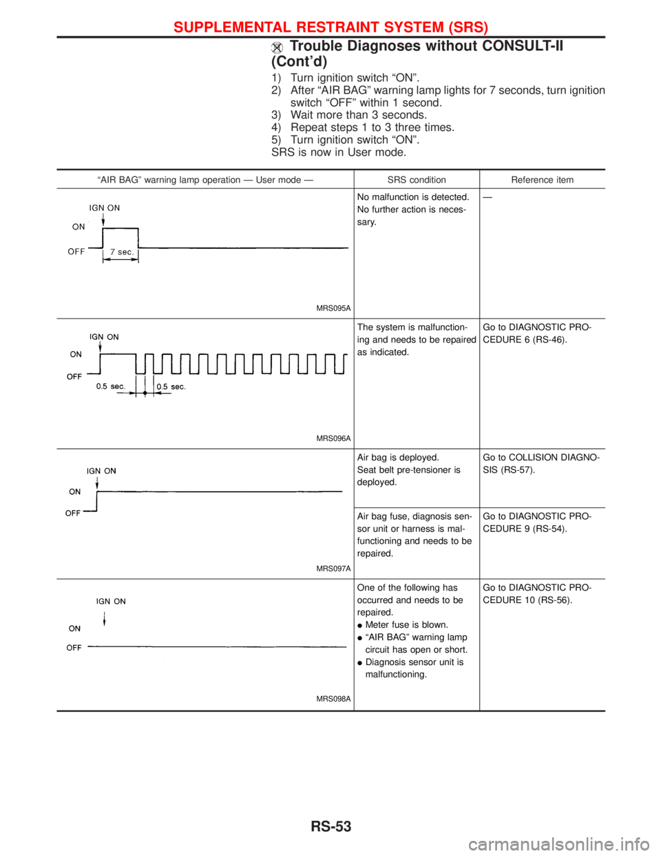
1) Turn ignition switch ªONº.
2) After ªAIR BAGº warning lamp lights for 7 seconds, turn ignition
switch ªOFFº within 1 second.
3) Wait more than 3 seconds.
4) Repeat steps 1 to 3 three times.
5) Turn ignition switch ªONº.
SRS is now in User mode.
ªAIR BAGº warning lamp operation Ð User mode Ð SRS condition Reference item
MRS095A
No malfunction is detected.
No further action is neces-
sary.Ð
MRS096A
The system is malfunction-
ing and needs to be repaired
as indicated.Go to DIAGNOSTIC PRO-
CEDURE 6 (RS-46).
MRS097A
Air bag is deployed.
Seat belt pre-tensioner is
deployed.Go to COLLISION DIAGNO-
SIS (RS-57).
Air bag fuse, diagnosis sen-
sor unit or harness is mal-
functioning and needs to be
repaired.Go to DIAGNOSTIC PRO-
CEDURE 9 (RS-54).
MRS098A
One of the following has
occurred and needs to be
repaired.
IMeter fuse is blown.
IªAIR BAGº warning lamp
circuit has open or short.
IDiagnosis sensor unit is
malfunctioning.Go to DIAGNOSTIC PRO-
CEDURE 10 (RS-56).
SUPPLEMENTAL RESTRAINT SYSTEM (SRS)
Trouble Diagnoses without CONSULT-II
(Cont'd)
RS-53
Page 1675 of 1767

DIAGNOSTIC PROCEDURE 8 (CONTINUED FROM
DIAGNOSTIC PROCEDURE 6)
Inspecting SRS malfunctioning record
1 CONSIDER POSSIBILITY OF NOT ERASING SELF-DIAGNOSTIC RESULT AFTER REPAIRING
Is it the first time for maintenance of SRS?
YesorNo
Ye sEGo to DIAGNOSTIC PROCEDURE 5 (RS-42). (Further inspection cannot be performed without CONSULT-II.)
NoEDiagnosis results (previously stored in the memory) might not be erased after repair. Go to DIAGNOSTIC PRO-
CEDURE 7, step 5 (RS-51).
Trouble Diagnoses: ªAIR BAGº Warning Lamp
Does Not Turn Off
DIAGNOSTIC PROCEDURE 9
1 SEE THE DEPLOYMENT OF AIR BAG MODULE
Is air bag module deployed?
YesorNo
Ye sERefer to COLLISION DIAGNOSIS (RS-57).
NoEGO TO 2.
2 CHECK AIR BAG FUSE
Is SRS ªAir Bagº fuse OK?
NRS093
OK or NG
OKEGO TO 4.
NGEGO TO 3.
3 CHECK AIR BAG FUSE AGAIN
Replace ªAIR BAGº fuse and turn ignition switch ON.
Is ªAIR BAGº fuse blown again?
Ye sERepair main harness.
NoEINSPECTION END
SUPPLEMENTAL RESTRAINT SYSTEM (SRS)
Trouble Diagnoses without CONSULT-II
(Cont'd)
RS-54
Page 1677 of 1767

Trouble Diagnoses: ªAIR BAGº Warning Lamp
Does Not Turn On
DIAGNOSTIC PROCEDURE 10
1 CHECK ªMETERº FUSE
Is meter fuse OK?
NRS092
OK or NG
OKEGO TO 3.
NGEGO TO 2.
2 CHECK ªMETERº FUSE AGAIN
Replace meter fuse and turn ignition switch ON.
Is meter fuse blown again?
Ye sERepair main harness.
NoEINSPECTION END
3 CHECK ªAIR BAGº WARNING LAMP LED
Is ªAIR BAGº warning lamp LED OK?
OK or NG
OKEGO TO 4.
NGEReplace ªAIR BAGº warning lamp LED.
4 CHECK HARNESS CONNECTION BETWEEN DIAGNOSIS SENSOR UNIT AND ªAIR BAGº WARNING LAMP
Disconnect diagnosis sensor unit connector and turn ignition switch ªONº.
IDoes ªAIR BAGº warning lamp turn on?
YesorNo
Ye sEReplace diagnosis sensor unit.
NoECheck the ground circuit of ªAIR BAGº warning lamp.
SUPPLEMENTAL RESTRAINT SYSTEM (SRS)
RS-56
Page 1694 of 1767
System Description
M/T MODELS
Power is supplied at all times
Ithrough 40A fusible link (letterC, located in the fuse and fusible link box)
Ito ignition switch terminal 1.
With the ignition switch in START position, power is supplied
Ifrom ignition switch terminal 1
Ito starter motor harness connector terminal 4.
The starter motor plunger closes and provides a closed circuit between the battery and starter motor. The
starter motor is grounded to the engine block. With power and ground supplied, cranking occurs and the engine
starts.
A/T MODELS
Power is supplied at all times
Ithrough 40A fusible link (letterC, located in the fuse and fusible link box)
Ito ignition switch terminal 1.
With the ignition switch in the START position, power is supplied
Ifrom ignition switch terminal 1
Ito park/neutral position relay terminal 4.
With the ignition switch ON or START position, power is supplied
Ithrough 10A fuse [No. 8, located in the fuse block (J/B)]
Ito park/neutral position (PNP) relay terminal 1.
With the selector lever in the P or N position, ground is supplied
Ito park/neutral position relay terminal 2 through the park/neutral position switch
Ifrom body grounds, M754 and M33.
Then park/neutral position relay is energized and power is supplied
Ifrom park/neutral position relay terminal 3
Ito starter motor harness connector terminal 1.
The starter motor plunger closes and provides a closed circuit between the battery and starter motor. The
starter motor is grounded to the engine block. With power and ground supplied, cranking occurs and the engine
starts.
STARTING SYSTEM
SC-13
Page 1704 of 1767
System Description
The alternator provides DC voltage to operate the vehicle's electrical system and to keep the battery charged.
The voltage output is controlled by the IC regulator.
Power is supplied at all times to alternator terminal 4 (S) through:
I10A fuse (No. 31, located in the fuse and fusible link box).
Terminal B supplies power to charge the battery and operate the vehicle's electrical system. Output voltage
is controlled by the IC regulator at terminal 4 (S) detecting the input voltage (ZD30DDTi engine models). The
charging circuit is protected by the 100A (A/T models) fusible link.
The alternator is grounded to the engine block.
With the ignition switch in the ON or START position, power is supplied
Ithrough 10A fuse [No. 12, located in the fuse block (J/B)]
Ito combination meter terminal 28 for the charge warning lamp.
Ground is supplied to terminal 2 of the combination meter through terminal 1(L) (TD27Ti engine models) or
3(L) (ZD30DDTi engine model) of the alternator. With power and ground supplied, the charge warning lamp
will illuminate. When the alternator is providing sufficient voltage with the engine running, the ground is opened
and the charge warning lamp will go off.
If the charge warning lamp illuminates with the engine running, a malfunction is indicated.
CHARGING SYSTEM
SC-23