sensor NISSAN TERRANO 2002 Service Workshop Manual
[x] Cancel search | Manufacturer: NISSAN, Model Year: 2002, Model line: TERRANO, Model: NISSAN TERRANO 2002Pages: 1767, PDF Size: 41.51 MB
Page 206 of 1767
Preparation
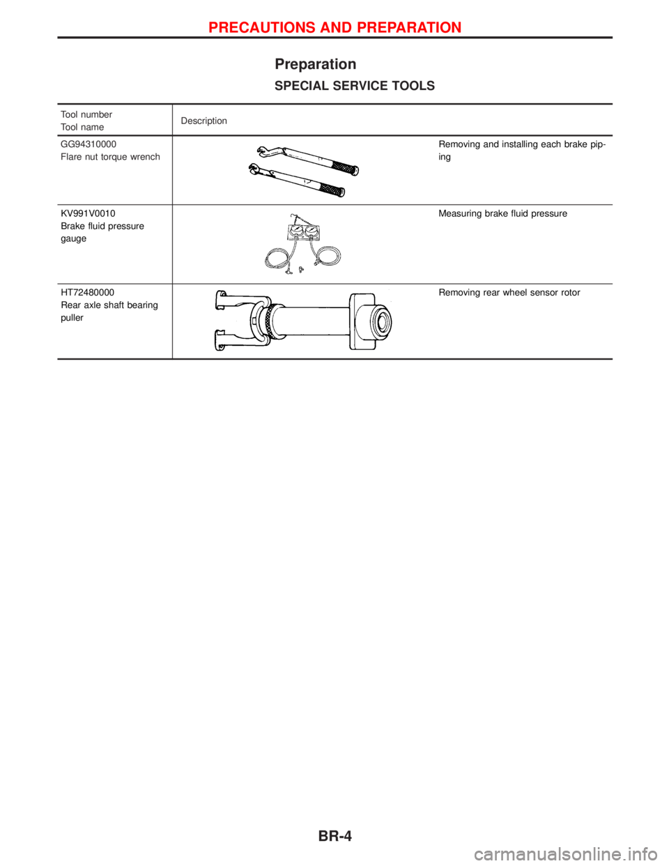
SPECIAL SERVICE TOOLS
Tool number
Tool nameDescription
GG94310000
Flare nut torque wrench
Removing and installing each brake pip-
ing
KV991V0010
Brake fluid pressure
gauge
Measuring brake fluid pressure
HT72480000
Rear axle shaft bearing
puller
Removing rear wheel sensor rotor
PRECAUTIONS AND PREPARATION
BR-4
Page 215 of 1767
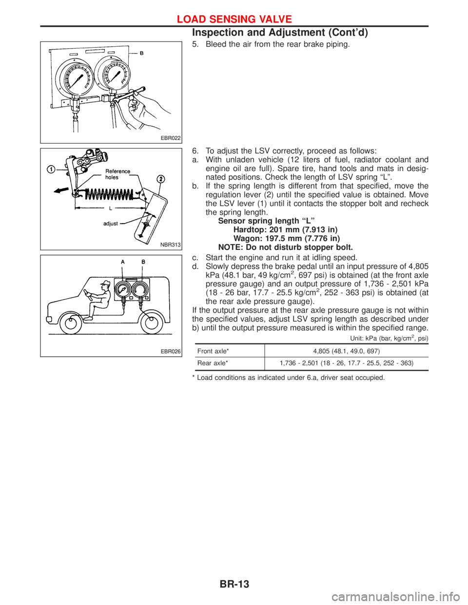
5. Bleed the air from the rear brake piping.
6. To adjust the LSV correctly, proceed as follows:
a. With unladen vehicle (12 liters of fuel, radiator coolant and
engine oil are full). Spare tire, hand tools and mats in desig-
nated positions. Check the length of LSV spring ªLº.
b. If the spring length is different from that specified, move the
regulation lever (2) until the specified value is obtained. Move
the LSV lever (1) until it contacts the stopper bolt and recheck
the spring length.
Sensor spring length ªLº
Hardtop: 201 mm (7.913 in)
Wagon: 197.5 mm (7.776 in)
NOTE: Do not disturb stopper bolt.
c. Start the engine and run it at idling speed.
d. Slowly depress the brake pedal until an input pressure of 4,805
kPa (48.1 bar, 49 kg/cm
2, 697 psi) is obtained (at the front axle
pressure gauge) and an output pressure of 1,736 - 2,501 kPa
(18 - 26 bar, 17.7 - 25.5 kg/cm
2, 252 - 363 psi) is obtained (at
the rear axle pressure gauge).
If the output pressure at the rear axle pressure gauge is not within
the specified values, adjust LSV spring length as described under
b) until the output pressure measured is within the specified range.
Unit: kPa (bar, kg/cm2, psi)
Front axle* 4,805 (48.1, 49.0, 697)
Rear axle* 1,736 - 2,501 (18 - 26, 17.7 - 25.5, 252 - 363)
* Load conditions as indicated under 6.a, driver seat occupied.
EBR022
NBR313
EBR026
LOAD SENSING VALVE
Inspection and Adjustment (Cont'd)
BR-13
Page 240 of 1767
System Description
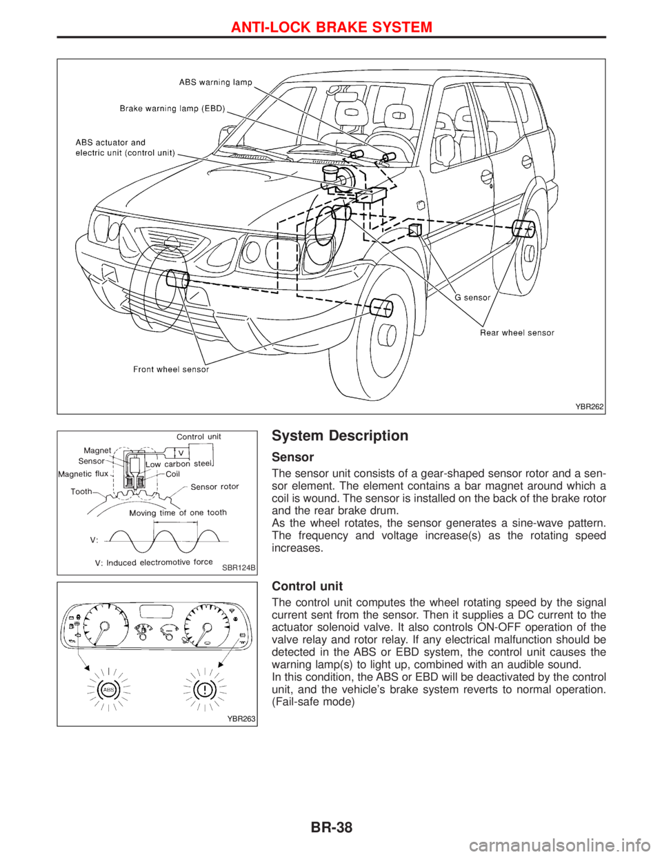
Sensor
The sensor unit consists of a gear-shaped sensor rotor and a sen-
sor element. The element contains a bar magnet around which a
coil is wound. The sensor is installed on the back of the brake rotor
and the rear brake drum.
As the wheel rotates, the sensor generates a sine-wave pattern.
The frequency and voltage increase(s) as the rotating speed
increases.
Control unit
The control unit computes the wheel rotating speed by the signal
current sent from the sensor. Then it supplies a DC current to the
actuator solenoid valve. It also controls ON-OFF operation of the
valve relay and rotor relay. If any electrical malfunction should be
detected in the ABS or EBD system, the control unit causes the
warning lamp(s) to light up, combined with an audible sound.
In this condition, the ABS or EBD will be deactivated by the control
unit, and the vehicle's brake system reverts to normal operation.
(Fail-safe mode)
YBR262
SBR124B
YBR263
ANTI-LOCK BRAKE SYSTEM
BR-38
Page 241 of 1767

G SENSOR
The G sensor analyses deceleration during braking to determine whether the vehicle is being driven on a road
with low surface resistance () (snow-covered road, etc.). The ABS control unit uses the signal from the
deceleration sensor to compensate for road surface conditions when controlling the braking operation.
NBR136
ANTI-LOCK BRAKE SYSTEM
System Description (Cont'd)
BR-39
Page 244 of 1767
Removal and Installation
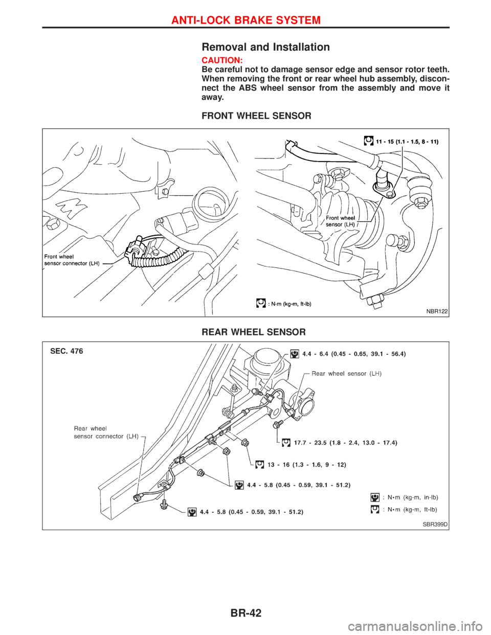
CAUTION:
Be careful not to damage sensor edge and sensor rotor teeth.
When removing the front or rear wheel hub assembly, discon-
nect the ABS wheel sensor from the assembly and move it
away.
FRONT WHEEL SENSOR
REAR WHEEL SENSOR
NBR122
SBR399D
ANTI-LOCK BRAKE SYSTEM
BR-42
Page 245 of 1767
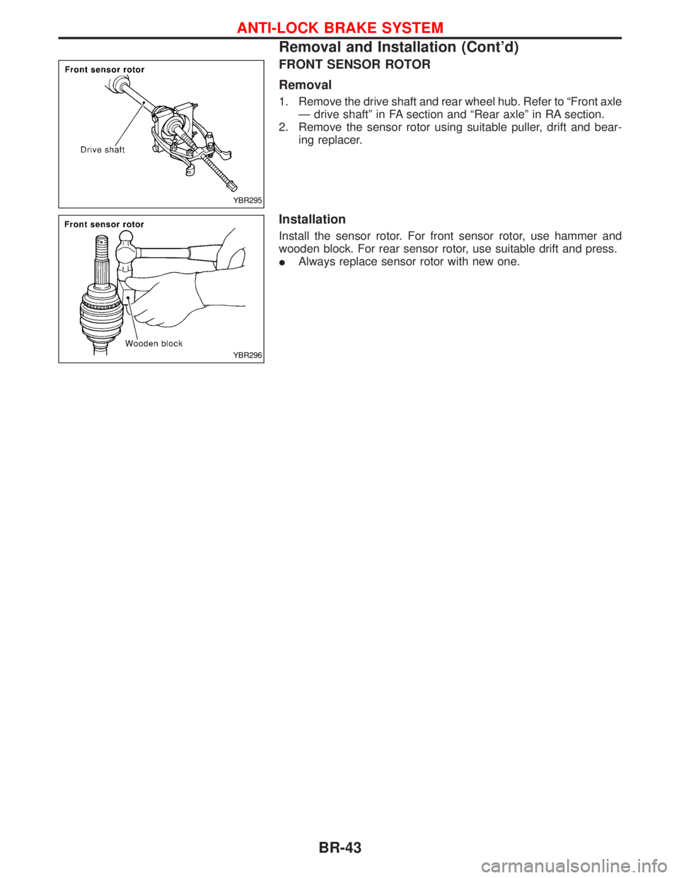
FRONT SENSOR ROTOR
Removal
1. Remove the drive shaft and rear wheel hub. Refer to ªFront axle
Ð drive shaftº in FA section and ªRear axleº in RA section.
2. Remove the sensor rotor using suitable puller, drift and bear-
ing replacer.
Installation
Install the sensor rotor. For front sensor rotor, use hammer and
wooden block. For rear sensor rotor, use suitable drift and press.
IAlways replace sensor rotor with new one.
YBR295
YBR296
ANTI-LOCK BRAKE SYSTEM
Removal and Installation (Cont'd)
BR-43
Page 246 of 1767
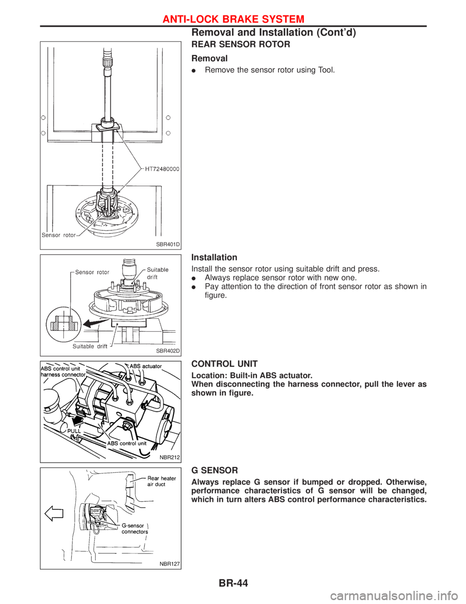
REAR SENSOR ROTOR
Removal
IRemove the sensor rotor using Tool.
Installation
Install the sensor rotor using suitable drift and press.
IAlways replace sensor rotor with new one.
IPay attention to the direction of front sensor rotor as shown in
figure.
CONTROL UNIT
Location: Built-in ABS actuator.
When disconnecting the harness connector, pull the lever as
shown in figure.
G SENSOR
Always replace G sensor if bumped or dropped. Otherwise,
performance characteristics of G sensor will be changed,
which in turn alters ABS control performance characteristics.
SBR401D
SBR402D
NBR212
NBR127
ANTI-LOCK BRAKE SYSTEM
Removal and Installation (Cont'd)
BR-44
Page 249 of 1767
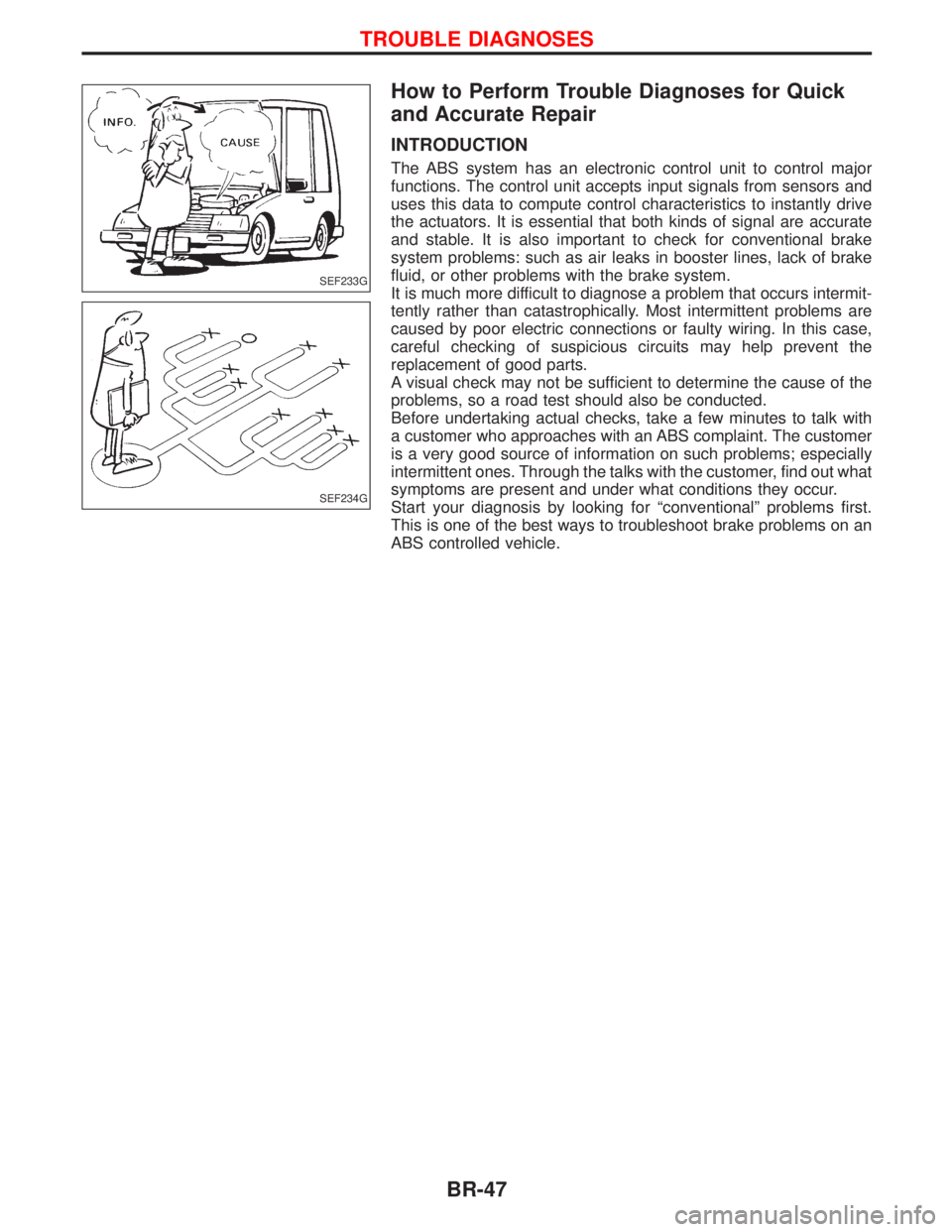
How to Perform Trouble Diagnoses for Quick
and Accurate Repair
INTRODUCTION
The ABS system has an electronic control unit to control major
functions. The control unit accepts input signals from sensors and
uses this data to compute control characteristics to instantly drive
the actuators. It is essential that both kinds of signal are accurate
and stable. It is also important to check for conventional brake
system problems: such as air leaks in booster lines, lack of brake
fluid, or other problems with the brake system.
It is much more difficult to diagnose a problem that occurs intermit-
tently rather than catastrophically. Most intermittent problems are
caused by poor electric connections or faulty wiring. In this case,
careful checking of suspicious circuits may help prevent the
replacement of good parts.
A visual check may not be sufficient to determine the cause of the
problems, so a road test should also be conducted.
Before undertaking actual checks, take a few minutes to talk with
a customer who approaches with an ABS complaint. The customer
is a very good source of information on such problems; especially
intermittent ones. Through the talks with the customer, find out what
symptoms are present and under what conditions they occur.
Start your diagnosis by looking for ªconventionalº problems first.
This is one of the best ways to troubleshoot brake problems on an
ABS controlled vehicle.
SEF233G
SEF234G
TROUBLE DIAGNOSES
BR-47
Page 260 of 1767
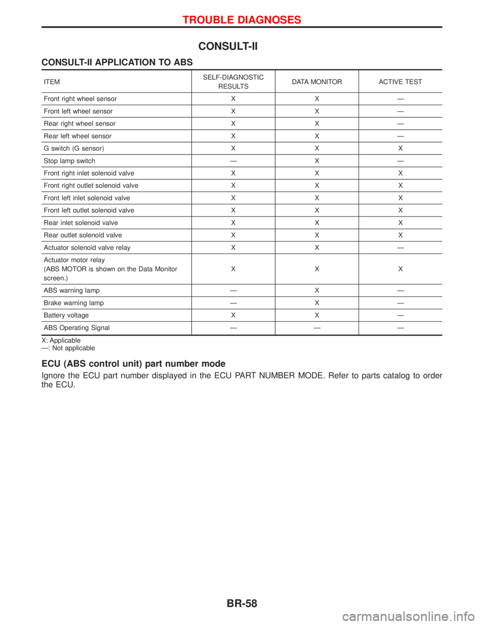
CONSULT-II
CONSULT-II APPLICATION TO ABS
ITEMSELF-DIAGNOSTIC
RESULTSDATA MONITOR ACTIVE TEST
Front right wheel sensor X X Ð
Front left wheel sensor X X Ð
Rear right wheel sensor X X Ð
Rear left wheel sensor X X Ð
G switch (G sensor) X X X
Stop lamp switch Ð X Ð
Front right inlet solenoid valve X X X
Front right outlet solenoid valve X X X
Front left inlet solenoid valve X X X
Front left outlet solenoid valve X X X
Rear inlet solenoid valve X X X
Rear outlet solenoid valve X X X
Actuator solenoid valve relay X X Ð
Actuator motor relay
(ABS MOTOR is shown on the Data Monitor
screen.)XXX
ABS warning lamp Ð X Ð
Brake warning lamp Ð X Ð
Battery voltage X X Ð
ABS Operating Signal Ð Ð Ð
X: Applicable
Ð: Not applicable
ECU (ABS control unit) part number mode
Ignore the ECU part number displayed in the ECU PART NUMBER MODE. Refer to parts catalog to order
the ECU.
TROUBLE DIAGNOSES
BR-58
Page 262 of 1767
![NISSAN TERRANO 2002 Service Workshop Manual SELF-DIAGNOSTIC RESULTS MODE
Diagnostic item Diagnostic item is detected when...Diagnostic
procedure
FR RH SENSORH
[OPEN]ICircuit for front right wheel sensor is open.
(An abnormally high input voltag NISSAN TERRANO 2002 Service Workshop Manual SELF-DIAGNOSTIC RESULTS MODE
Diagnostic item Diagnostic item is detected when...Diagnostic
procedure
FR RH SENSORH
[OPEN]ICircuit for front right wheel sensor is open.
(An abnormally high input voltag](/img/5/57393/w960_57393-261.png)
SELF-DIAGNOSTIC RESULTS MODE
Diagnostic item Diagnostic item is detected when...Diagnostic
procedure
FR RH SENSORH
[OPEN]ICircuit for front right wheel sensor is open.
(An abnormally high input voltage is entered.)4
FR LH SENSORH
[OPEN]ICircuit for front left wheel sensor is open.
(An abnormally high input voltage is entered.)4
RR RH SENSORH
[OPEN]ICircuit for rear right sensor is open.
(An abnormally high input voltage is entered.)4
RR LH SENSORH
[OPEN]ICircuit for rear left sensor is open.
(An abnormally high input voltage is entered.)4
FR RH SENSORH
[SHORT]ICircuit for front right wheel sensor is shorted.
(An abnormally low input voltage is entered.)4
FR LH SENSORH
[SHORT]ICircuit for front left wheel sensor is shorted.
(An abnormally low input voltage is entered.)4
RR RH SENSORH
[SHORT]ICircuit for rear right sensor is shorted.
(An abnormally low input voltage is entered.)4
RR LH SENSORH
[SHORT]ICircuit for rear left sensor is shorted.
(An abnormally low input voltage is entered.)4
ABS SENSORH
[ABNORMAL SIGNAL]ITeeth damage on sensor rotor or misalignment of wheel sensor.
(Abnormal wheel sensor signal is entered.)4
FR RH IN ABS SOL
[OPEN, SHORT]ICircuit for front right inlet solenoid valve is open or shorted.
(An abnormally low output voltage is entered.)3
FR LH IN ABS SOL
[OPEN, SHORT]ICircuit for front left inlet solenoid valve is open or shorted.
(An abnormally low output voltage is entered.)3
FR RH OUT ABS SOL
[OPEN, SHORT]ICircuit for front right outlet solenoid valve is open or shorted.
(An abnormally low output voltage is entered.)3
FR LH OUT ABS SOL
[OPEN, SHORT]ICircuit for front left outlet solenoid valve is open or shorted.
(An abnormally low output voltage is entered.)3
RR IN ABS SOL
[OPEN, SHORT]ICircuit for rear right outlet solenoid valve is open or shorted.
(An abnormally high output voltage is entered.)3
RR OUT ABS SOL
[OPEN, SHORT]ICircuit for rear left outlet solenoid valve is open or shorted.
(An abnormally high output voltage is entered.)3
ABS ACTUATOR RELAY
[ABNORMAL]IActuator solenoid valve relay is ON, even if control unit sends OFF signal.
IActuator solenoid valve relay is OFF, even if control unit sends ON signal.6
ABS MOTOR RELAY
[ABNORMAL]ICircuit for ABS motor relay is open or shorted.
ICircuit for actuator motor is open or shorted.
IActuator motor relay is stuck.5
BATTERY VOLT
[VB-LOW]IPower source voltage supplied to ABS control unit is abnormally low. 7
CONTROL UNITIFunction of calculation in ABS control unit has failed. 9
G-SENSOR
[ABNORMAL]IG sensor is open.8
HIf a tire slips on rough roads for more than 10 seconds, the ABS warning lamp may come on. In this case, the malfunctioning code
regarding the wheel sensors may be memorized. Turn off the ignition switch, restart the engine and drive the vehicle at speeds
above 30 km/h (19 MPH).
TROUBLE DIAGNOSES
CONSULT-II Inspection Procedure (Cont'd)
BR-60