Full system NISSAN TERRANO 2002 Service Repair Manual
[x] Cancel search | Manufacturer: NISSAN, Model Year: 2002, Model line: TERRANO, Model: NISSAN TERRANO 2002Pages: 1767, PDF Size: 41.51 MB
Page 6 of 1767
Supplemental Restraint System (SRS) ªAIR
BAGº and ªSEAT BELT PRE-TENSIONERº
The Supplemental Restraint System such as ªAIR BAGº and ªSEAT BELT PRE-TENSIONERº used along with
a seat belt, helps to reduce the risk or severity of injury to the driver and front passenger in a frontal collision.
The SRS system composition which is available to NISSAN MODEL R20 is as follows (The composition var-
ies according to the destination.):
Driver air bag module (located in the center of the steering wheel), front passenger air bag module (located
on the instrument panel on passenger side), seat belt pre-tensioner, a diagnosis sensor unit, warning lamp,
wiring harness and spiral cable.
Information necessary to service the system safely is included in theRS sectionof this Service Manual.
WARNING:
ITo avoid rendering the SRS inoperative, which could increase the risk of personal injury or death
in the event of a collision which would result in air bag inflation, all maintenance must be performed
by an authorized NISSAN dealer.
IImproper maintenance, including incorrect removal and installation of the SRS, can lead to per-
sonal injury caused by unintentional activation of the system. For removal of Spiral Cable and Air
Bag Module, see the RS section.
IDo not use electrical test equipment on any circuit related to the SRS unless instructed to in this
Service Manual. Spiral cable and wiring harnesses covered with yellow insulation either just before
the harness connectors or for the complete harness are related to the SRS.
Precautions
IBefore proceeding with disassembly, thoroughly clean the outside of the transmission. It is important to
prevent the internal parts from becoming contaminated by dirt or other foreign matter.
IDisassembly should be done in a clean work area.
IUse lint-free cloth or towels for wiping parts clean. Common shop rags can leave fibers that could inter-
fere with the operation of the transmission.
IPlace disassembled parts in order for easier and proper assembly.
IAll parts should be carefully cleaned with a general purpose, non-flammable solvent before inspection or
reassembly.
IGaskets, seals and O-rings should be replaced any time the transmission is disassembled.
IIt is very important to perform functional tests whenever they are indicated.
IThe valve body contains precision parts and requires extreme care when parts are removed and serviced.
Place removed parts in a parts rack in order to replace them in correct positions and sequences. Care will
also prevent springs and small parts from becoming scattered or lost.
IProperly installed valves, sleeves, plugs, etc. will slide along bores in valve body under their own weight.
IBefore assembly, apply a coat of recommended ATF to all parts. Apply petroleum jelly to protect O-rings
and seals, and to hold bearings and washers in place during assembly. Do not use grease.
IExtreme care should be taken to avoid damage to O-rings, seals and gaskets when assembling.
IAfter overhaul, refill the transmission with new ATF.
IWhen the A/T drain plug is removed, only some of the fluid is drained. Old A/T fluid will remain in torque
converter and ATF cooling system.
Always follow the procedures under ªChanging A/T Fluidº in the MA section when changing A/T fluid.
PREPARATION AND PRECAUTIONS
AT- 4
Page 15 of 1767
TCM FUNCTION
The function of the TCM is to:
IReceive input signals sent from various switches and sensors.
IDetermine required line pressure, shifting point, lock-up operation, and engine brake operation.
ISend required output signals to the respective solenoids.
INPUT/OUTPUT SIGNAL OF TCM
Sensors and solenoid valves Function
InputPark/neutral position switch Detects select lever position and sends a signal to TCM.
Throttle (accelerator) position sensor Detects throttle valve position and sends a signal to TCM.
Closed throttle position switch Detects throttle valve's fully-closed position and sends a signal to TCM.
Wide open throttle position switchDetects a throttle valve position of greater than 1/2 of full throttle and sends a
signal to TCM.
Engine speed signal From ECM.
A/T fluid temperature sensor Detects transmission fluid temperature and sends a signal to TCM.
Revolution sensor Detects output shaft rpm and sends a signal to TCM.
Vehicle speed sensorUsed as an auxiliary vehicle speed sensor. Sends a signal when revolution sen-
sor (installed on transmission) malfunctions.
Overdrive control switch
A/T mode switchSends a signal, which prohibits a shift to ªD
4º (overdrive) position, to the TCM.
OutputShift solenoid valve A/BSelects shifting point suited to driving conditions in relation to a signal sent from
TCM.
Line pressure solenoid valveRegulates (or decreases) line pressure suited to driving conditions in relation to
a signal sent from TCM.
Torque converter clutch solenoid valveRegulates (or decreases) lock-up pressure suited to driving conditions in relation
to a signal sent from TCM.
Overrun clutch solenoid valveControls an ªengine brakeº effect suited to driving conditions in relation to a sig-
nal sent from TCM.
O/D OFF indicator lamp
SPORT indicator lampShows TCM malfunctions, when A/T control components malfunction.
OVERALL SYSTEM
Control System (Cont'd)
AT-13
Page 18 of 1767
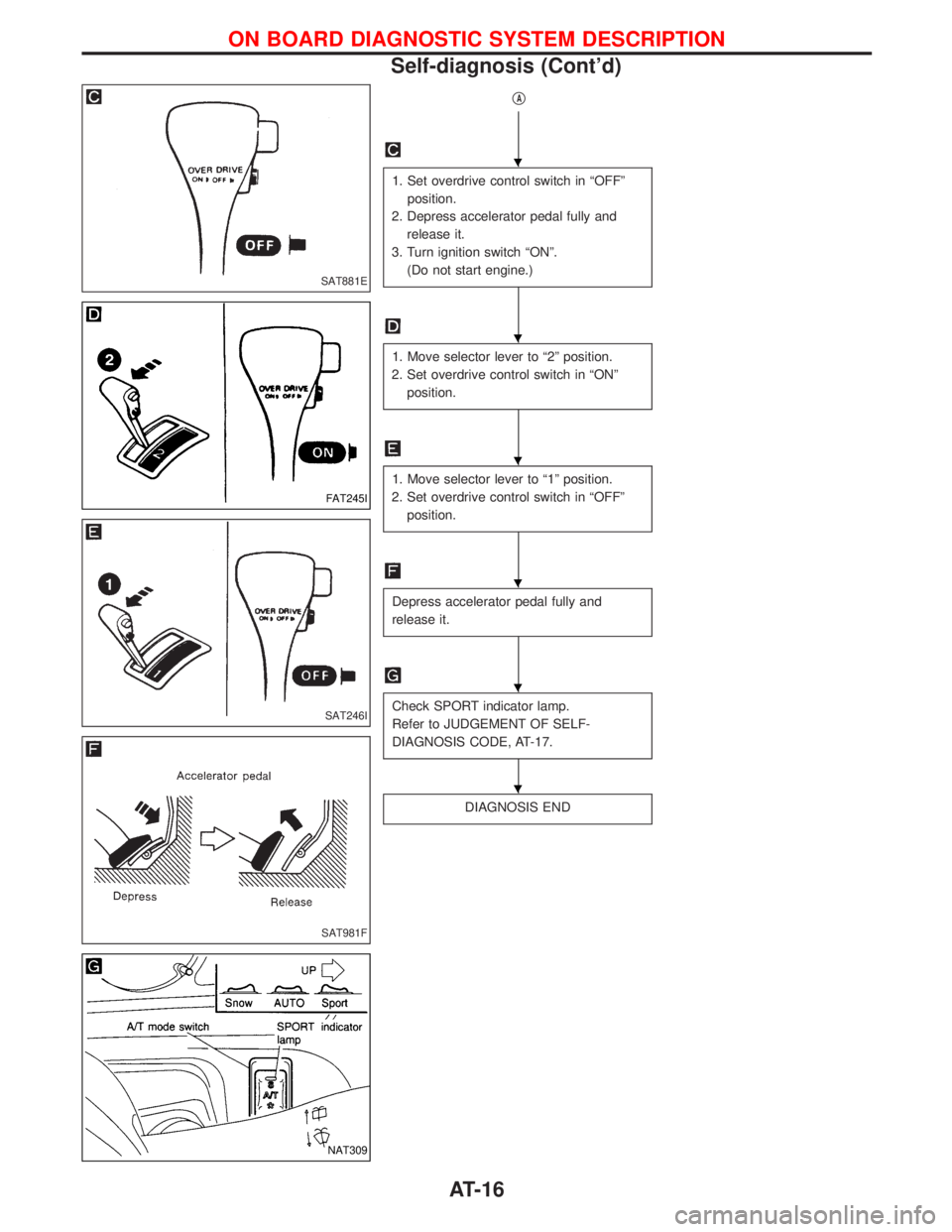
qA
1. Set overdrive control switch in ªOFFº
position.
2. Depress accelerator pedal fully and
release it.
3. Turn ignition switch ªONº.
(Do not start engine.)
1. Move selector lever to ª2º position.
2. Set overdrive control switch in ªONº
position.
1. Move selector lever to ª1º position.
2. Set overdrive control switch in ªOFFº
position.
Depress accelerator pedal fully and
release it.
Check SPORT indicator lamp.
Refer to JUDGEMENT OF SELF-
DIAGNOSIS CODE, AT-17.
DIAGNOSIS END
SAT881E
FAT245I
SAT246I
SAT981F
NAT309
H
H
H
H
H
H
ON BOARD DIAGNOSTIC SYSTEM DESCRIPTION
Self-diagnosis (Cont'd)
AT-16
Page 28 of 1767
Work Flow
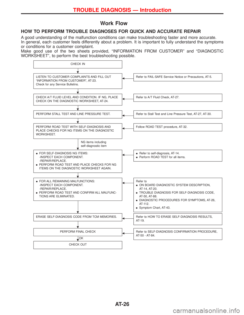
HOW TO PERFORM TROUBLE DIAGNOSES FOR QUICK AND ACCURATE REPAIR
A good understanding of the malfunction conditions can make troubleshooting faster and more accurate.
In general, each customer feels differently about a problem. It is important to fully understand the symptoms
or conditions for a customer complaint.
Make good use of the two sheets provided, ªINFORMATION FROM CUSTOMERº and ªDIAGNOSTIC
WORKSHEETº, to perform the best troubleshooting possible.
CHECK IN
LISTEN TO CUSTOMER COMPLAINTS AND FILL OUT
ªINFORMATION FROM CUSTOMERº, AT-23.
Check for any Service Bulletins.FRefer to FAIL-SAFE Service Notice or Precautions, AT-5.
CHECK A/T FLUID LEVEL AND CONDITION. IF NG, PLACE
CHECK ON THE DIAGNOSTIC WORKSHEET, AT-24.FRefer to A/T Fluid Check, AT-27.
PERFORM STALL TEST AND LINE PRESSURE TEST.FRefer to Stall Test and Line Pressure Test, AT-27, AT-30.
PERFORM ROAD TEST WITH SELF-DIAGNOSIS AND
PLACE CHECKS FOR NG ITEMS ON THE DIAGNOSTIC
WORKSHEET.
NG items including
self-diagnostic item
FFollow ROAD TEST procedure, AT-32.
IFOR SELF-DIAGNOSIS NG ITEMS:
-INSPECT EACH COMPONENT.
-REPAIR/REPLACE.
IPERFORM ROAD TEST AND PLACE CHECKS FOR NG
ITEMS ON THE DIAGNOSTIC WORKSHEET AGAIN.FIRefer to self-diagnosis, AT-14.
IPerform ROAD TEST for all items.
IFOR ALL REMAINING MALFUNCTIONS:
-INSPECT EACH COMPONENT.
-REPAIR/REPLACE.
IPERFORM ROAD TEST AND CONFIRM ALL MALFUNC-
TIONS ARE ELIMINATED.FRefer to
ION BOARD DIAGNOSTIC SYSTEM DESCRIPTION,
AT-14, AT-20.
ITROUBLE DIAGNOSIS FOR SELF-DIAGNOSIS CODE,
AT-50, AT-88.
IDIAGNOSTIC PROCEDURES FOR SYMPTOMS, AT-26,
AT-112.
ISymptom Chart, AT-43.
ERASE SELF-DIAGNOSIS CODE FROM TCM MEMORIES.FRefer to HOW TO ERASE SELF-DIAGNOSIS RESULTS,
AT-19.
PERFORM FINAL CHECK
OK
FRefer to SELF-DIAGNOSIS CONFIRMATION PROCEDURE,
AT-50 - AT-84.
CHECK OUT
H
H
H
H
H
H
H
H
H
TROUBLE DIAGNOSIS Ð Introduction
AT-26
Page 63 of 1767
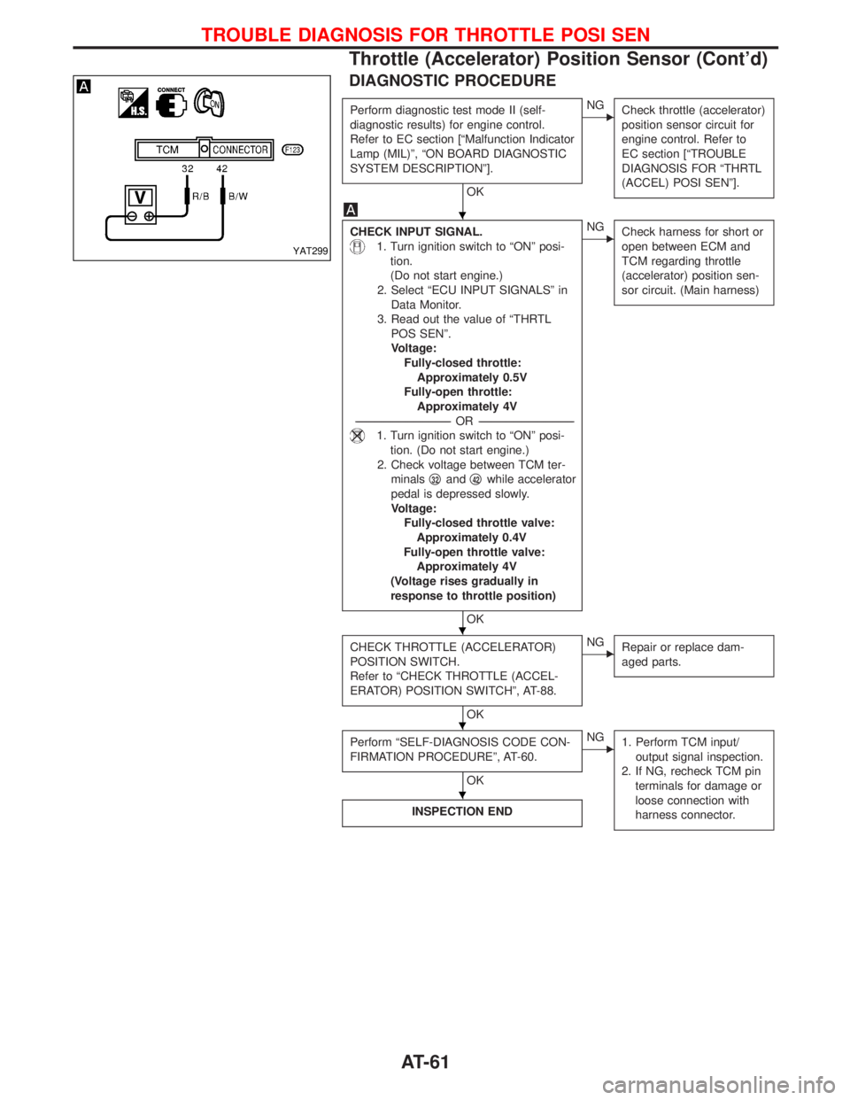
DIAGNOSTIC PROCEDURE
Perform diagnostic test mode II (self-
diagnostic results) for engine control.
Refer to EC section [ªMalfunction Indicator
Lamp (MIL)º, ªON BOARD DIAGNOSTIC
SYSTEM DESCRIPTIONº].
OK
ENG
Check throttle (accelerator)
position sensor circuit for
engine control. Refer to
EC section [ªTROUBLE
DIAGNOSIS FOR ªTHRTL
(ACCEL) POSI SENº].
CHECK INPUT SIGNAL.
1. Turn ignition switch to ªONº posi-
tion.
(Do not start engine.)
2. Select ªECU INPUT SIGNALSº in
Data Monitor.
3. Read out the value of ªTHRTL
POS SENº.
Voltage:
Fully-closed throttle:
Approximately 0.5V
Fully-open throttle:
Approximately 4V
-----------------------------------------------------------------------------------------------------------------------OR -----------------------------------------------------------------------------------------------------------------------
1. Turn ignition switch to ªONº posi-
tion. (Do not start engine.)
2. Check voltage between TCM ter-
minalsq
32andq42while accelerator
pedal is depressed slowly.
Voltage:
Fully-closed throttle valve:
Approximately 0.4V
Fully-open throttle valve:
Approximately 4V
(Voltage rises gradually in
response to throttle position)
OK
ENG
Check harness for short or
open between ECM and
TCM regarding throttle
(accelerator) position sen-
sor circuit. (Main harness)
CHECK THROTTLE (ACCELERATOR)
POSITION SWITCH.
Refer to ªCHECK THROTTLE (ACCEL-
ERATOR) POSITION SWITCHº, AT-88.
OK
ENG
Repair or replace dam-
aged parts.
Perform ªSELF-DIAGNOSIS CODE CON-
FIRMATION PROCEDUREº, AT-60.
OK
ENG
1. Perform TCM input/
output signal inspection.
2. If NG, recheck TCM pin
terminals for damage or
loose connection with
harness connector.
INSPECTION END
YAT299
H
H
H
H
TROUBLE DIAGNOSIS FOR THROTTLE POSI SEN
Throttle (Accelerator) Position Sensor (Cont'd)
AT-61
Page 207 of 1767
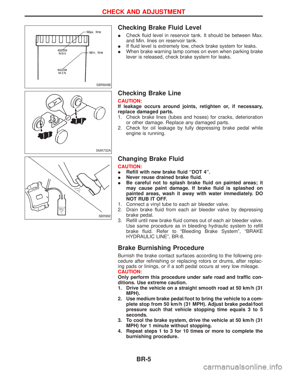
Checking Brake Fluid Level
ICheck fluid level in reservoir tank. It should be between Max.
and Min. lines on reservoir tank.
IIf fluid level is extremely low, check brake system for leaks.
IWhen brake warning lamp comes on even when parking brake
lever is released, check brake system for leaks.
Checking Brake Line
CAUTION:
If leakage occurs around joints, retighten or, if necessary,
replace damaged parts.
1. Check brake lines (tubes and hoses) for cracks, deterioration
or other damage. Replace any damaged parts.
2. Check for oil leakage by fully depressing brake pedal while
engine is running.
Changing Brake Fluid
CAUTION:
IRefill with new brake fluid ªDOT 4º.
INever reuse drained brake fluid.
IBe careful not to splash brake fluid on painted areas; it
may cause paint damage. If brake fluid is splashed on
painted areas, wash it away with water immediately. DO
NOT RUB IT OFF.
1. Connect a vinyl tube to each air bleeder valve.
2. Drain brake fluid from each air bleeder valve by depressing
brake pedal.
3. Refill until new brake fluid comes out of each air bleeder valve.
Use same procedure as in bleeding hydraulic system to refill
brake fluid. Refer to ªBleeding Brake Systemº, ªBRAKE
HYDRAULIC LINEº, BR-8.
Brake Burnishing Procedure
Burnish the brake contact surfaces according to the following pro-
cedure after refinishing or replacing rotors or drums, after replac-
ing pads or linings, or if a soft pedal occurs at very low mileage.
CAUTION:
Only perform this procedure under safe road and traffic con-
ditions. Use extreme caution.
1. Drive the vehicle on a straight smooth road at 50 km/h (31
MPH).
2. Use medium brake pedal/foot to bring the vehicle to a com-
plete stop from 50 km/h (31 MPH). Adjust brake pedal/foot
pressure such that vehicle stopping time equals 3 to 5
seconds.
3. To cool the brake system, drive the vehicle at 50 km/h (31
MPH) for 1 minute without stopping.
4. Repeat steps 1 to 3 for 10 times or more to complete the
burnishing procedure.
SBR849B
SMA732A
SBR992
CHECK AND ADJUSTMENT
BR-5
Page 210 of 1767
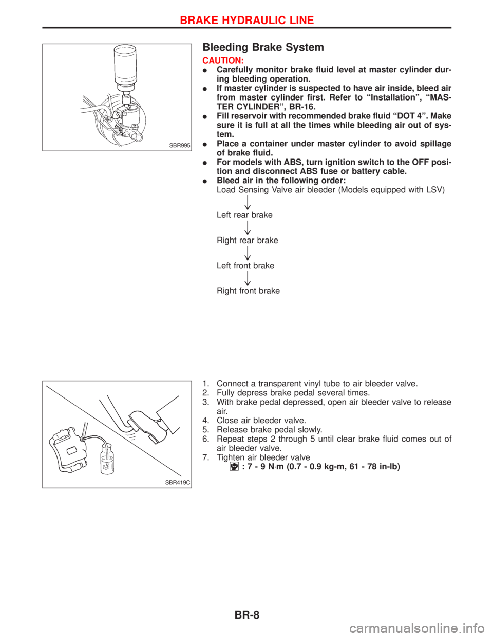
Bleeding Brake System
CAUTION:
ICarefully monitor brake fluid level at master cylinder dur-
ing bleeding operation.
IIf master cylinder is suspected to have air inside, bleed air
from master cylinder first. Refer to ªInstallationº, ªMAS-
TER CYLINDERº, BR-16.
IFill reservoir with recommended brake fluid ªDOT 4º. Make
sure it is full at all the times while bleeding air out of sys-
tem.
IPlace a container under master cylinder to avoid spillage
of brake fluid.
IFor models with ABS, turn ignition switch to the OFF posi-
tion and disconnect ABS fuse or battery cable.
IBleed air in the following order:
Load Sensing Valve air bleeder (Models equipped with LSV)
"
Left rear brake
"
Right rear brake
"
Left front brake
"
Right front brake
1. Connect a transparent vinyl tube to air bleeder valve.
2. Fully depress brake pedal several times.
3. With brake pedal depressed, open air bleeder valve to release
air.
4. Close air bleeder valve.
5. Release brake pedal slowly.
6. Repeat steps 2 through 5 until clear brake fluid comes out of
air bleeder valve.
7. Tighten air bleeder valve
:7-9N×m (0.7 - 0.9 kg-m, 61 - 78 in-lb)
SBR995
SBR419C
BRAKE HYDRAULIC LINE
BR-8
Page 217 of 1767
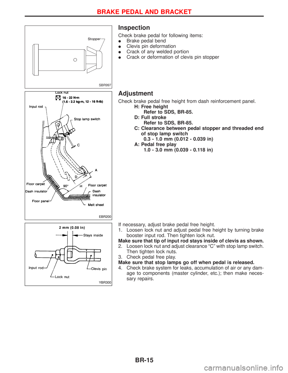
Inspection
Check brake pedal for following items:
IBrake pedal bend
IClevis pin deformation
ICrack of any welded portion
ICrack or deformation of clevis pin stopper
Adjustment
Check brake pedal free height from dash reinforcement panel.
H: Free height
Refer to SDS, BR-85.
D: Full stroke
Refer to SDS, BR-85.
C: Clearance between pedal stopper and threaded end
of stop lamp switch
0.3 - 1.0 mm (0.012 - 0.039 in)
A: Pedal free play
1.0 - 3.0 mm (0.039 - 0.118 in)
If necessary, adjust brake pedal free height.
1. Loosen lock nut and adjust pedal free height by turning brake
booster input rod. Then tighten lock nut.
Make sure that tip of input rod stays inside of clevis as shown.
2. Loosen lock nut and adjust clearance ªCº with stop lamp switch.
Then tighten lock nuts.
3. Check pedal free play.
Make sure that stop lamps go off when pedal is released.
4. Check brake system for leaks, accumulation of air or any dam-
age to components (master cylinder, etc.); then make neces-
sary repairs.
SBR997
EBR200
YBR300
BRAKE PEDAL AND BRACKET
BR-15
Page 248 of 1767
6. Loosen/remove mounting nuts between actuator and bracket.
Installation
CAUTION:
After installation, pay attention to the following points:
IRefill brake fluid and bleed air. Refer to ªCHECK AND
ADJUSTMENTº, BR-5 and ªBleeding Brake Systemº,
ªBRAKE HYDRAULIC LINEº, BR-8, respectively.
1. Install actuator on bracket without tightening fixings.
2. Assemble brake tubes to actuator without tightening tube nuts.
Ensure that correct tubes are connected to each port.
3. Fully tighten actuator and bracket fixings to specified torque.
4. Fully tighten flare nuts to specified torque, BR-9.
5. Secure ABS control unit harness connector and battery cable.
ANTI-LOCK BRAKE SYSTEM
Removal and Installation (Cont'd)
BR-46
Page 290 of 1767
Service Notice
IWhen removing or installing various parts, place a cloth or padding onto the vehicle body to prevent
scratches.
IHandle trim, molding, instruments, grille, etc. carefully during removing or installing. Be careful not to oil
or damage them.
IApply sealing compound where necessary when installing parts.
IWhen applying sealing compound, be careful that the sealing compound does not protrude from parts.
IWhen replacing any metal parts (for example body outer panel, members, etc.), be sure to take rust pre-
vention measures.
Supplemental Restraint System (SRS) ªAIR
BAGº and ªSEAT BELT PRE-TENSIONERº
The Supplemental Restraint System such as ªAIR BAGº and ªSEAT BELT PRE-TENSIONERº used along with
a seat belt, helps to reduce the risk or severity of injury to the driver and front passenger for certain types of
collision. The SRS system composition which is available to NISSAN MODEL R20 is as follows (The compo-
sition varies according to the destination and optional equipment.):
IFor a frontal collision
The Supplemental Restraint System consists of driver air bag module (located in the center of the steer-
ing wheel), front passenger air bag module (located on the instrument panel on passenger side), front seat
belt pre-tensioners, a diagnosis sensor unit, warning lamp, wiring harness and spiral cable.
IFor a side collision
The Supplemental Restraint System consists of front side air bag module (located in the outer side of front
seat), side air bag (satellite) sensor, diagnosis sensor unit (one of components of air bags for a frontal
collision), wiring harness, warning lamp (one of components of air bags for a frontal collision).
Information necessary to service the system safely is included in theRSsection of this Service Manual.
WARNING:
ITo avoid rendering the SRS inoperative, which could increase the risk of personal injury or death
in the event of a collision which would result in air bag inflation, all maintenance should be per-
formed by an authorized NISSAN dealer.
IImproper maintenance, including incorrect removal and installation of the SRS, can lead to per-
sonal injury caused by unintentional activation of the system. For removal of Spiral Cable and Air
Bag Module, see the RS section.
IDo not use electrical test equipment on any circuit related to the SRS unless instructed to in this
Service Manual. Spiral cable and wiring harnesses covered with yellow insulation tape either just
before the harness connectors or for the complete harness are related to the SRS.
PRECAUTIONS
BT-2