transmission fluid NISSAN TERRANO 2002 Service Repair Manual
[x] Cancel search | Manufacturer: NISSAN, Model Year: 2002, Model line: TERRANO, Model: NISSAN TERRANO 2002Pages: 1767, PDF Size: 41.51 MB
Page 3 of 1767
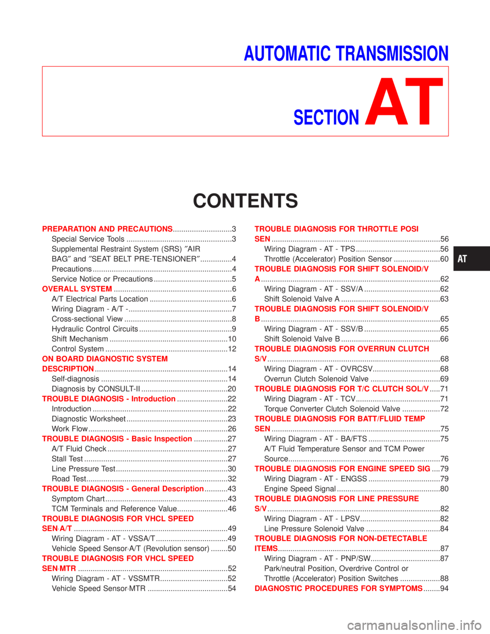
AUTOMATIC TRANSMISSION
SECTION
AT
CONTENTS
PREPARATION AND PRECAUTIONS............................3
Special Service Tools ..................................................3
Supplemental Restraint System (SRS)²AIR
BAG²and²SEAT BELT PRE-TENSIONER²...............4
Precautions ..................................................................4
Service Notice or Precautions .....................................5
OVERALL SYSTEM........................................................6
A/T Electrical Parts Location .......................................6
Wiring Diagram - A/T -.................................................7
Cross-sectional View ...................................................8
Hydraulic Control Circuits ............................................9
Shift Mechanism ........................................................10
Control System ..........................................................12
ON BOARD DIAGNOSTIC SYSTEM
DESCRIPTION...............................................................14
Self-diagnosis ............................................................14
Diagnosis by CONSULT-II .........................................20
TROUBLE DIAGNOSIS - Introduction........................22
Introduction ................................................................22
Diagnostic Worksheet ................................................23
Work Flow ..................................................................26
TROUBLE DIAGNOSIS - Basic Inspection................27
A/T Fluid Check .........................................................27
Stall Test ....................................................................27
Line Pressure Test .....................................................30
Road Test...................................................................32
TROUBLE DIAGNOSIS - General Description...........43
Symptom Chart ..........................................................43
TCM Terminals and Reference Value........................46
TROUBLE DIAGNOSIS FOR VHCL SPEED
SEN×A/T.........................................................................49
Wiring Diagram - AT - VSSA/T ..................................49
Vehicle Speed Sensor×A/T (Revolution sensor) ........50
TROUBLE DIAGNOSIS FOR VHCL SPEED
SEN×MTR.......................................................................52
Wiring Diagram - AT - VSSMTR ................................52
Vehicle Speed Sensor×MTR ......................................54TROUBLE DIAGNOSIS FOR THROTTLE POSI
SEN................................................................................56
Wiring Diagram - AT - TPS ........................................56
Throttle (Accelerator) Position Sensor ......................60
TROUBLE DIAGNOSIS FOR SHIFT SOLENOID/V
A.....................................................................................62
Wiring Diagram - AT - SSV/A ....................................62
Shift Solenoid Valve A ...............................................63
TROUBLE DIAGNOSIS FOR SHIFT SOLENOID/V
B.....................................................................................65
Wiring Diagram - AT - SSV/B ....................................65
Shift Solenoid Valve B ...............................................66
TROUBLE DIAGNOSIS FOR OVERRUN CLUTCH
S/V..................................................................................68
Wiring Diagram - AT - OVRCSV................................68
Overrun Clutch Solenoid Valve .................................69
TROUBLE DIAGNOSIS FOR T/C CLUTCH SOL/V.....71
Wiring Diagram - AT - TCV........................................71
Torque Converter Clutch Solenoid Valve ..................72
TROUBLE DIAGNOSIS FOR BATT/FLUID TEMP
SEN................................................................................75
Wiring Diagram - AT - BA/FTS ..................................75
A/T Fluid Temperature Sensor and TCM Power
Source........................................................................76
TROUBLE DIAGNOSIS FOR ENGINE SPEED SIG....79
Wiring Diagram - AT - ENGSS ..................................79
Engine Speed Signal .................................................80
TROUBLE DIAGNOSIS FOR LINE PRESSURE
S/V..................................................................................82
Wiring Diagram - AT - LPSV......................................82
Line Pressure Solenoid Valve ...................................84
TROUBLE DIAGNOSIS FOR NON-DETECTABLE
ITEMS.............................................................................87
Wiring Diagram - AT - PNP/SW.................................87
Park/neutral Position, Overdrive Control or
Throttle (Accelerator) Position Switches ...................88
DIAGNOSTIC PROCEDURES FOR SYMPTOMS........94
Page 6 of 1767
Supplemental Restraint System (SRS) ªAIR
BAGº and ªSEAT BELT PRE-TENSIONERº
The Supplemental Restraint System such as ªAIR BAGº and ªSEAT BELT PRE-TENSIONERº used along with
a seat belt, helps to reduce the risk or severity of injury to the driver and front passenger in a frontal collision.
The SRS system composition which is available to NISSAN MODEL R20 is as follows (The composition var-
ies according to the destination.):
Driver air bag module (located in the center of the steering wheel), front passenger air bag module (located
on the instrument panel on passenger side), seat belt pre-tensioner, a diagnosis sensor unit, warning lamp,
wiring harness and spiral cable.
Information necessary to service the system safely is included in theRS sectionof this Service Manual.
WARNING:
ITo avoid rendering the SRS inoperative, which could increase the risk of personal injury or death
in the event of a collision which would result in air bag inflation, all maintenance must be performed
by an authorized NISSAN dealer.
IImproper maintenance, including incorrect removal and installation of the SRS, can lead to per-
sonal injury caused by unintentional activation of the system. For removal of Spiral Cable and Air
Bag Module, see the RS section.
IDo not use electrical test equipment on any circuit related to the SRS unless instructed to in this
Service Manual. Spiral cable and wiring harnesses covered with yellow insulation either just before
the harness connectors or for the complete harness are related to the SRS.
Precautions
IBefore proceeding with disassembly, thoroughly clean the outside of the transmission. It is important to
prevent the internal parts from becoming contaminated by dirt or other foreign matter.
IDisassembly should be done in a clean work area.
IUse lint-free cloth or towels for wiping parts clean. Common shop rags can leave fibers that could inter-
fere with the operation of the transmission.
IPlace disassembled parts in order for easier and proper assembly.
IAll parts should be carefully cleaned with a general purpose, non-flammable solvent before inspection or
reassembly.
IGaskets, seals and O-rings should be replaced any time the transmission is disassembled.
IIt is very important to perform functional tests whenever they are indicated.
IThe valve body contains precision parts and requires extreme care when parts are removed and serviced.
Place removed parts in a parts rack in order to replace them in correct positions and sequences. Care will
also prevent springs and small parts from becoming scattered or lost.
IProperly installed valves, sleeves, plugs, etc. will slide along bores in valve body under their own weight.
IBefore assembly, apply a coat of recommended ATF to all parts. Apply petroleum jelly to protect O-rings
and seals, and to hold bearings and washers in place during assembly. Do not use grease.
IExtreme care should be taken to avoid damage to O-rings, seals and gaskets when assembling.
IAfter overhaul, refill the transmission with new ATF.
IWhen the A/T drain plug is removed, only some of the fluid is drained. Old A/T fluid will remain in torque
converter and ATF cooling system.
Always follow the procedures under ªChanging A/T Fluidº in the MA section when changing A/T fluid.
PREPARATION AND PRECAUTIONS
AT- 4
Page 14 of 1767
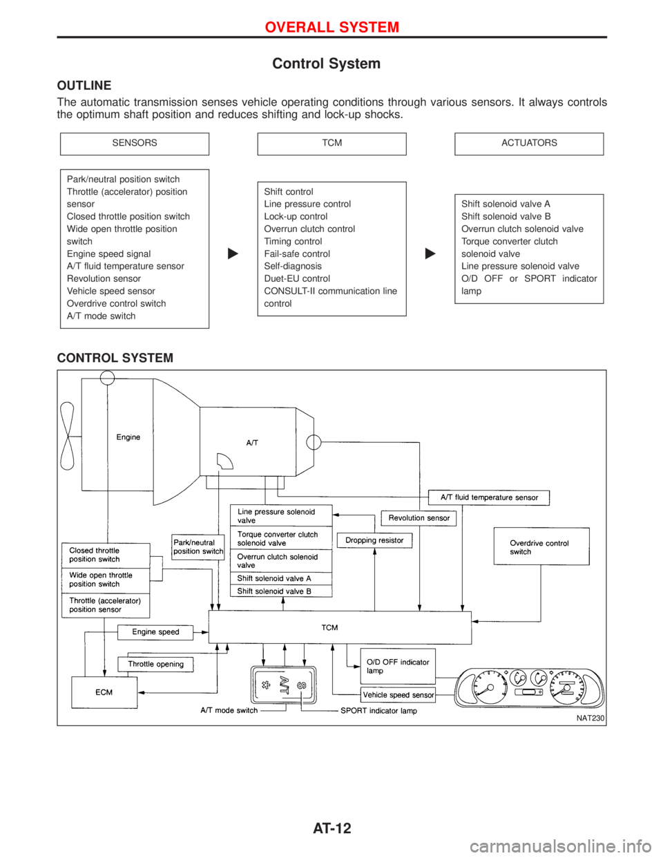
Control System
OUTLINE
The automatic transmission senses vehicle operating conditions through various sensors. It always controls
the optimum shaft position and reduces shifting and lock-up shocks.
SENSORSTCMACTUATORS
Park/neutral position switch
Throttle (accelerator) position
sensor
Closed throttle position switch
Wide open throttle position
switch
Engine speed signal
A/T fluid temperature sensor
Revolution sensor
Vehicle speed sensor
Overdrive control switch
A/T mode switch
E
Shift control
Line pressure control
Lock-up control
Overrun clutch control
Timing control
Fail-safe control
Self-diagnosis
Duet-EU control
CONSULT-II communication line
control
E
Shift solenoid valve A
Shift solenoid valve B
Overrun clutch solenoid valve
Torque converter clutch
solenoid valve
Line pressure solenoid valve
O/D OFF or SPORT indicator
lamp
CONTROL SYSTEM
NAT230
OVERALL SYSTEM
AT-12
Page 15 of 1767
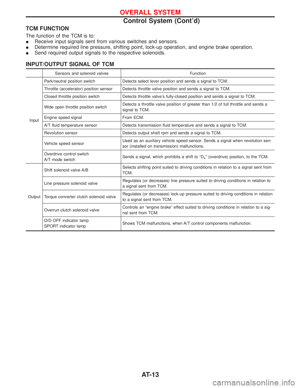
TCM FUNCTION
The function of the TCM is to:
IReceive input signals sent from various switches and sensors.
IDetermine required line pressure, shifting point, lock-up operation, and engine brake operation.
ISend required output signals to the respective solenoids.
INPUT/OUTPUT SIGNAL OF TCM
Sensors and solenoid valves Function
InputPark/neutral position switch Detects select lever position and sends a signal to TCM.
Throttle (accelerator) position sensor Detects throttle valve position and sends a signal to TCM.
Closed throttle position switch Detects throttle valve's fully-closed position and sends a signal to TCM.
Wide open throttle position switchDetects a throttle valve position of greater than 1/2 of full throttle and sends a
signal to TCM.
Engine speed signal From ECM.
A/T fluid temperature sensor Detects transmission fluid temperature and sends a signal to TCM.
Revolution sensor Detects output shaft rpm and sends a signal to TCM.
Vehicle speed sensorUsed as an auxiliary vehicle speed sensor. Sends a signal when revolution sen-
sor (installed on transmission) malfunctions.
Overdrive control switch
A/T mode switchSends a signal, which prohibits a shift to ªD
4º (overdrive) position, to the TCM.
OutputShift solenoid valve A/BSelects shifting point suited to driving conditions in relation to a signal sent from
TCM.
Line pressure solenoid valveRegulates (or decreases) line pressure suited to driving conditions in relation to
a signal sent from TCM.
Torque converter clutch solenoid valveRegulates (or decreases) lock-up pressure suited to driving conditions in relation
to a signal sent from TCM.
Overrun clutch solenoid valveControls an ªengine brakeº effect suited to driving conditions in relation to a sig-
nal sent from TCM.
O/D OFF indicator lamp
SPORT indicator lampShows TCM malfunctions, when A/T control components malfunction.
OVERALL SYSTEM
Control System (Cont'd)
AT-13
Page 29 of 1767
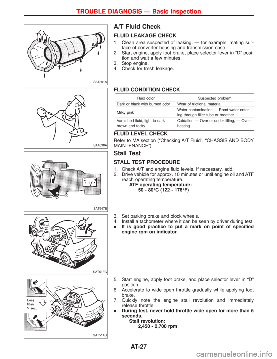
A/T Fluid Check
FLUID LEAKAGE CHECK
1. Clean area suspected of leaking. Ð for example, mating sur-
face of converter housing and transmission case.
2. Start engine, apply foot brake, place selector lever in ªDº posi-
tion and wait a few minutes.
3. Stop engine.
4. Check for fresh leakage.
FLUID CONDITION CHECK
Fluid color Suspected problem
Dark or black with burned odor Wear of frictional material
Milky pinkWater contamination Ð Road water enter-
ing through filler tube or breather
Varnished fluid, light to dark
brown and tackyOxidation Ð Over or under filling, Ð Over-
heating
FLUID LEVEL CHECK
Refer to MA section (ªChecking A/T Fluidº, ªCHASSIS AND BODY
MAINTENANCEº).
Stall Test
STALL TEST PROCEDURE
1. Check A/T and engine fluid levels. If necessary, add.
2. Drive vehicle for approx. 10 minutes or until engine oil and ATF
reach operating temperature.
ATF operating temperature:
50 - 80ÉC (122 - 176ÉF)
3. Set parking brake and block wheels.
4. Install a tachometer where it can be seen by driver during test.
IIt is good practice to put a mark on point of specified
engine rpm on indicator.
5. Start engine, apply foot brake, and place selector lever in ªDº
position.
6. Accelerate to wide open throttle gradually while applying foot
brake.
7. Quickly note the engine stall revolution and immediately
release throttle.
IDuring test, never hold throttle wide open for more than 5
seconds.
Stall revolution:
2,450 - 2,700 rpm
SAT801A
SAT638A
SAT647B
SAT513G
SAT514G
TROUBLE DIAGNOSIS Ð Basic Inspection
AT-27
Page 45 of 1767
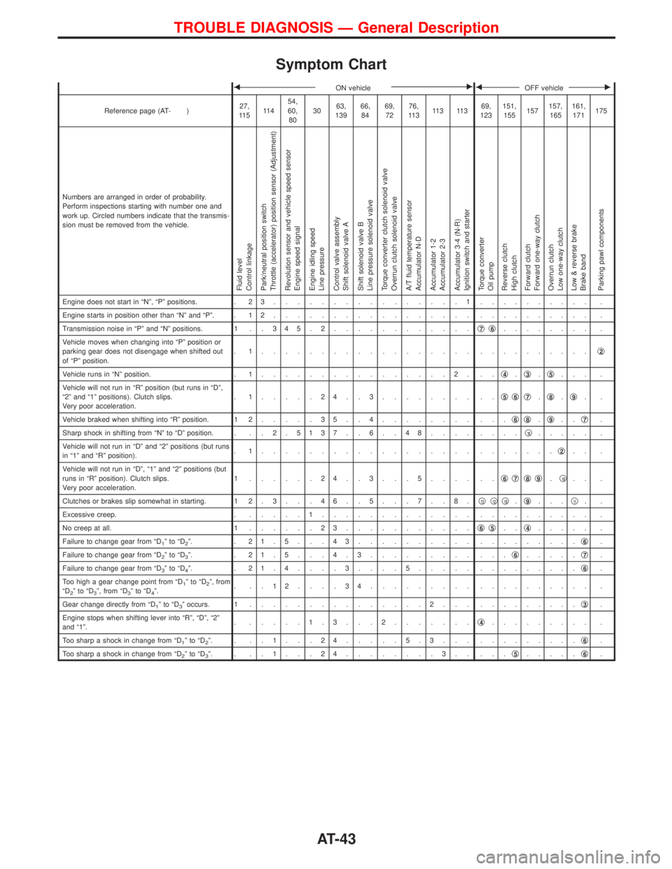
Symptom Chart
FON vehicleEFOFF vehicleE
Reference page (AT- )27,
11 511 454,
60,
803063,
13966,
8469,
7276,
11 311 3 11 369,
123151,
155157157,
165161,
171175
Numbers are arranged in order of probability.
Perform inspections starting with number one and
work up. Circled numbers indicate that the transmis-
sion must be removed from the vehicle.
Fluid level
Control linkage
Park/neutral position switch
Throttle (accelerator) position sensor (Adjustment)
Revolution sensor and vehicle speed sensor
Engine speed signal
Engine idling speed
Line pressure
Control valve assembly
Shift solenoid valve A
Shift solenoid valve B
Line pressure solenoid valve
Torque converter clutch solenoid valve
Overrun clutch solenoid valve
A/T fluid temperature sensor
Accumulator N-D
Accumulator 1-2
Accumulator 2-3
Accumulator 3-4 (N-R)
Ignition switch and starter
Torque converter
Oil pump
Reverse clutch
High clutch
Forward clutch
Forward one-way clutch
Overrun clutch
Low one-way clutch
Low & reverse brake
Brake band
Parking pawl components
Engine does not start in ªNº, ªPº positions. . 2 3................1.......... .
Engine starts in position other than ªNº and ªPº. . 1 2................. .......... .
Transmission noise in ªPº and ªNº positions. 1 . . 3 4 5 . 2............q
7q6........ .
Vehicle moves when changing into ªPº position or
parking gear does not disengage when shifted out
of ªPº position.. 1.................. ..........q
2
Vehicle runs in ªNº position. . 1................2. ..q4.q3.q5... .
Vehicle will not run in ªRº position (but runs in ªDº,
ª2º and ª1º positions). Clutch slips.
Very poor acceleration.. 1.....24..3........ ..q
5q6q7.q8.q9..
Vehicle braked when shifting into ªRº position. 1 2.....35..4........ ...q
6q8.q9..q7.
Sharp shock in shifting from ªNº to ªDº position. . . . 2 .5137 . . 6 . . 48.... ....q
10..... .
Vehicle will not run in ªDº and ª2º positions (but runs
in ª1º and ªRº position).. 1.................. .......q
2.. .
Vehicle will not run in ªDº, ª1º and ª2º positions (but
runs in ªRº position). Clutch slips.
Very poor acceleration.1 ......24..3...5.... ..q
6q7q8q9.q10.. .
Clutches or brakes slip somewhat in starting. 1 2 . 3 . . . 4 6 . . 5 . . . 7 . . 8 .q
13q12q10.q9...q11..
Excessive creep. ......1............. .......... .
No creep at all. 1......23...........q
6q5..q4..... .
Failure to change gear from ªD
1ºtoªD2º. . 21.5...43.......... .........q6.
Failure to change gear from ªD
2ºtoªD3º. . 21.5...4.3......... ...q6.....q7.
Failure to change gear from ªD
3ºtoªD4º. . 21.4....3....5..... .........q6.
Too high a gear change point from ªD
1ºtoªD2º, from
ªD2ºtoªD3º, from ªD3ºtoªD4º.. ..12....34......... .......... .
Gear change directly from ªD
1ºtoªD3º occurs. 1...............2... .........q3.
Engine stops when shifting lever into ªRº, ªDº, ª2º
and ª1º.. .....1.3...2.......q
4......... .
Too sharp a shock in change from ªD
1ºtoªD2º. . ..1...24.....5.3... .........q6.
Too sharp a shock in change from ªD
2ºtoªD3º. . ..1...24........3.. ...q5.....q6.
TROUBLE DIAGNOSIS Ð General Description
AT-43
Page 46 of 1767
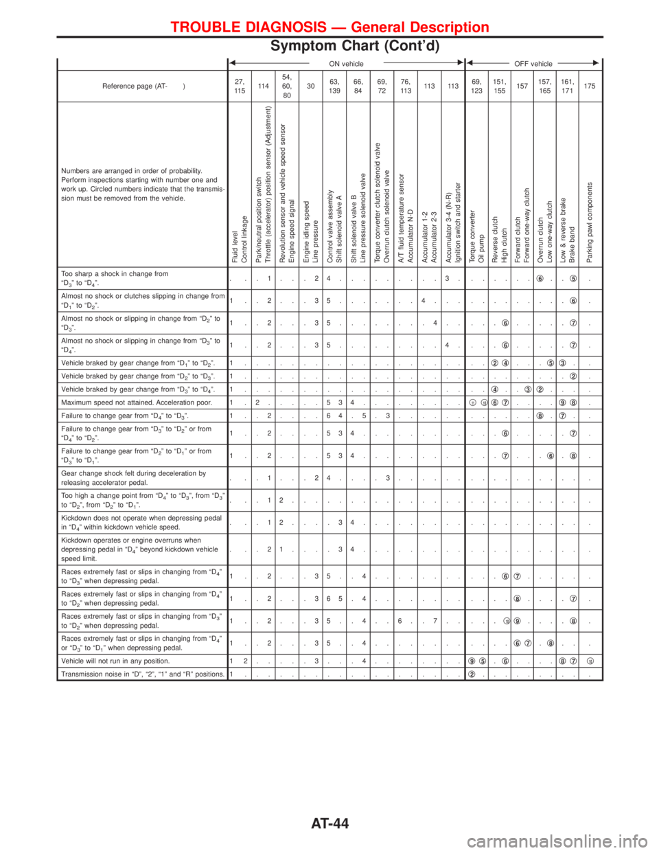
FON vehicleEFOFF vehicleE
Reference page (AT- )27,
11 511 454,
60,
803063,
13966,
8469,
7276,
11 311 3 11 369,
123151,
155157157,
165161,
171175
Numbers are arranged in order of probability.
Perform inspections starting with number one and
work up. Circled numbers indicate that the transmis-
sion must be removed from the vehicle.
Fluid level
Control linkage
Park/neutral position switch
Throttle (accelerator) position sensor (Adjustment)
Revolution sensor and vehicle speed sensor
Engine speed signal
Engine idling speed
Line pressure
Control valve assembly
Shift solenoid valve A
Shift solenoid valve B
Line pressure solenoid valve
Torque converter clutch solenoid valve
Overrun clutch solenoid valve
A/T fluid temperature sensor
Accumulator N-D
Accumulator 1-2
Accumulator 2-3
Accumulator 3-4 (N-R)
Ignition switch and starter
Torque converter
Oil pump
Reverse clutch
High clutch
Forward clutch
Forward one-way clutch
Overrun clutch
Low one-way clutch
Low & reverse brake
Brake band
Parking pawl components
Too sharp a shock in change from
ªD3ºtoªD4º.. ..1...24.........3. ......q6..q5.
Almost no shock or clutches slipping in change from
ªD
1ºtoªD2º.1 ..2...35.......4... .........q6.
Almost no shock or slipping in change from ªD
2ºto
ªD3º.1 ..2...35........4.. ...q6.....q7.
Almost no shock or slipping in change from ªD
3ºto
ªD4º.1 ..2...35.........4. ...q6.....q7.
Vehicle braked by gear change from ªD
1ºtoªD2º. 1 ................... ..q2q4...q5q3..
Vehicle braked by gear change from ªD
2ºtoªD3º. 1 ................... .........q2.
Vehicle braked by gear change from ªD
3ºtoªD4º. 1 ................... ..q4..q3q2... .
Maximum speed not attained. Acceleration poor. 1 . 2.....534.........q
11q10q6q7....q9q8.
Failure to change gear from ªD
4ºtoªD3º. 1 ..2....64.5.3...... ......q8.q7..
Failure to change gear from ªD
3ºtoªD2º or from
ªD4ºtoªD2º.1 ..2....534......... ...q6.....q7.
Failure to change gear from ªD
2ºtoªD1º or from
ªD3ºtoªD1º.1 ..2....534......... ...q7...q6.q8.
Gear change shock felt during deceleration by
releasing accelerator pedal.. ..1...24....3...... .......... .
Too high a change point from ªD
4ºtoªD3º, from ªD3º
to ªD2º, from ªD2ºtoªD1º.. ..12............... .......... .
Kickdown does not operate when depressing pedal
in ªD
4º within kickdown vehicle speed.. ..12....34......... .......... .
Kickdown operates or engine overruns when
depressing pedal in ªD
4º beyond kickdown vehicle
speed limit.. ..21....34......... .......... .
Races extremely fast or slips in changing from ªD
4º
to ªD3º when depressing pedal.1 ..2...35..4........ ...q6q7..... .
Races extremely fast or slips in changing from ªD
4º
to ªD2º when depressing pedal.1 ..2...365.4........ ....q8....q7.
Races extremely fast or slips in changing from ªD
3º
to ªD2º when depressing pedal.1 ..2...35..4..6..7.. ...q10q9....q8.
Races extremely fast or slips in changing from ªD
4º
or ªD3ºtoªD1º when depressing pedal.1 ..2...35..4........ ....q6q7.q8.. .
Vehicle will not run in any position. 1 2.....3...4........q
9q5.q6....q8q7q10
Transmission noise in ªDº, ª2º, ª1º and ªRº positions. 1...................q2......... .
TROUBLE DIAGNOSIS Ð General Description
Symptom Chart (Cont'd)
AT-44
Page 47 of 1767
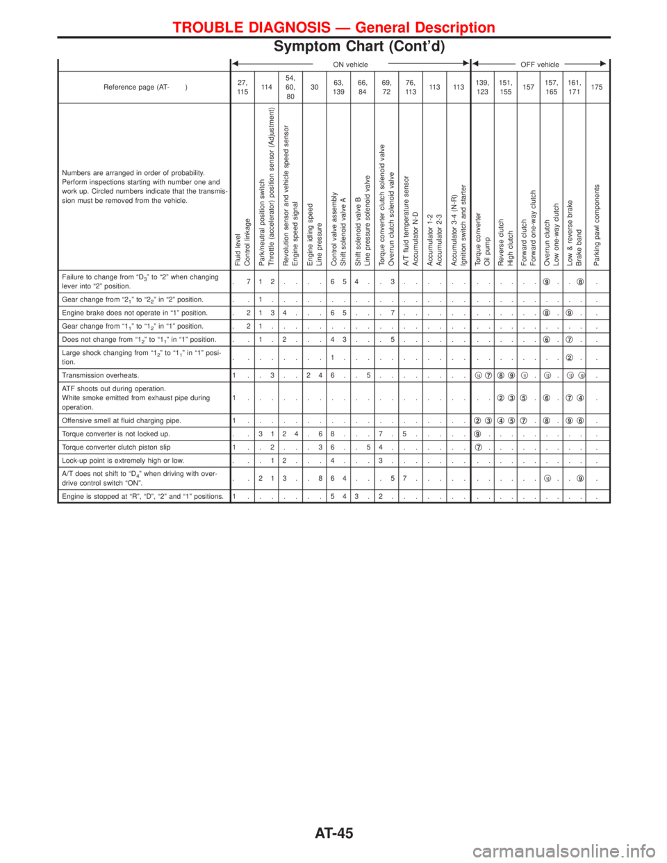
FON vehicleEFOFF vehicleE
Reference page (AT- )27,
11 511 454,
60,
803063,
13966,
8469,
7276,
11 311 3 11 3139,
123151,
155157157,
165161,
171175
Numbers are arranged in order of probability.
Perform inspections starting with number one and
work up. Circled numbers indicate that the transmis-
sion must be removed from the vehicle.
Fluid level
Control linkage
Park/neutral position switch
Throttle (accelerator) position sensor (Adjustment)
Revolution sensor and vehicle speed sensor
Engine speed signal
Engine idling speed
Line pressure
Control valve assembly
Shift solenoid valve A
Shift solenoid valve B
Line pressure solenoid valve
Torque converter clutch solenoid valve
Overrun clutch solenoid valve
A/T fluid temperature sensor
Accumulator N-D
Accumulator 1-2
Accumulator 2-3
Accumulator 3-4 (N-R)
Ignition switch and starter
Torque converter
Oil pump
Reverse clutch
High clutch
Forward clutch
Forward one-way clutch
Overrun clutch
Low one-way clutch
Low & reverse brake
Brake band
Parking pawl components
Failure to change from ªD3º to ª2º when changing
lever into ª2º position.. 712....654..3...... ......q9..q8.
Gear change from ª2
1ºtoª22º in ª2º position. . . 1................. .......... .
Engine brake does not operate in ª1º position. .2134 . . . 65 . . . 7...... ......q
8.q9..
Gear change from ª1
1ºtoª12º in ª1º position. . 2 1................. .......... .
Does not change from ª1
2ºtoª11º in ª1º position. . . 1 . 2 . . . 4 3 . . . 5...... ......q6.q7..
Large shock changing from ª1
2ºtoª11º in ª1º posi-
tion.. .......1........... ........q2..
Transmission overheats. 1 . . 3 . . 2 4 6 . . 5........q
14q7q8q9q11.q12.q13q10.
ATF shoots out during operation.
White smoke emitted from exhaust pipe during
operation.1 ................... ..q
2q3q5.q6.q7q4.
Offensive smell at fluid charging pipe. 1...................q
2q3q4q5q7.q8.q9q6.
Torque converter is not locked up. . .3124 . 68 . . . 7 . 5.....q
9......... .
Torque converter clutch piston slip 1 . . 2 . . . 3 6 . . 5 4.......q
7......... .
Lock-up point is extremely high or low. . . . 1 2 . . . 4 . . . 3....... .......... .
A/T does not shift to ªD
4º when driving with over-
drive control switch ªONº.. .213..864...57..... ......q10..q9.
Engine is stopped at ªRº, ªDº, ª2º and ª1º positions. 1.......543.2....... .......... .
TROUBLE DIAGNOSIS Ð General Description
Symptom Chart (Cont'd)
AT-45
Page 120 of 1767
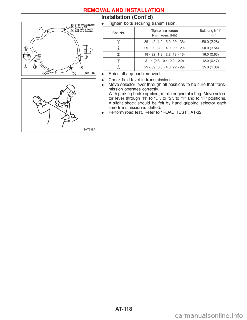
ITighten bolts securing transmission.
Bolt No.Tightening torque
N×m (kg-m, ft-lb)Bolt length ªº
mm (in)
q
139 - 49 (4.0 - 5.0, 29 - 36) 58.0 (2.28)
q
229 - 39 (3.0 - 4.0, 22 - 29) 90.0 (3.54)
q
318 - 22 (1.8 - 2.2, 13 - 16) 16.0 (0.63)
q
43 - 4 (0.3 - 0.4, 2.2 - 2.9) 12.0 (0.47)
q
529 - 39 (3.0 - 4.0, 22 - 29) 35.0 (1.38)
IReinstall any part removed.
ICheck fluid level in transmission.
IMove selector lever through all positions to be sure that trans-
mission operates correctly.
With parking brake applied, rotate engine at idling. Move selec-
tor lever through ªNº to ªDº, to ª2º, to ª1º and to ªRº positions.
A slight shock should be felt by hand gripping selector each
time transmission is shifted.
IPerform road test. Refer to ªROAD TESTº, AT-32.NAT287
SAT638A
REMOVAL AND INSTALLATION
Installation (Cont'd)
AT-118
Page 194 of 1767
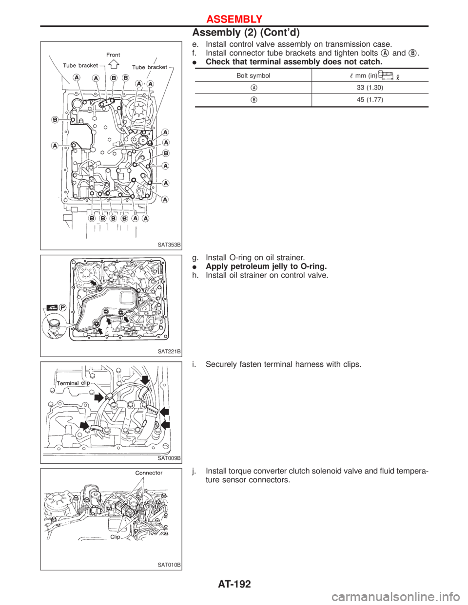
e. Install control valve assembly on transmission case.
f. Install connector tube brackets and tighten boltsq
AandqB.
ICheck that terminal assembly does not catch.
Bolt symbolmm (in)
qA33 (1.30)
q
B45 (1.77)
g. Install O-ring on oil strainer.
IApply petroleum jelly to O-ring.
h. Install oil strainer on control valve.
i. Securely fasten terminal harness with clips.
j. Install torque converter clutch solenoid valve and fluid tempera-
ture sensor connectors.
SAT353B
SAT221B
SAT009B
SAT010B
ASSEMBLY
Assembly (2) (Cont'd)
AT-192