battery NISSAN TERRANO 2002 Service Repair Manual
[x] Cancel search | Manufacturer: NISSAN, Model Year: 2002, Model line: TERRANO, Model: NISSAN TERRANO 2002Pages: 1767, PDF Size: 41.51 MB
Page 20 of 1767
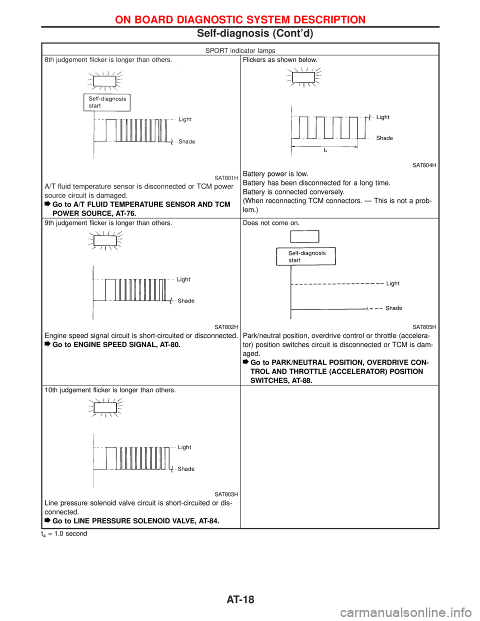
SPORT indicator lamps
8th judgement flicker is longer than others.
SAT801H
A/T fluid temperature sensor is disconnected or TCM power
source circuit is damaged.
Go to A/T FLUID TEMPERATURE SENSOR AND TCM
POWER SOURCE, AT-76.
Flickers as shown below.
SAT804H
Battery power is low.
Battery has been disconnected for a long time.
Battery is connected conversely.
(When reconnecting TCM connectors. Ð This is not a prob-
lem.)
9th judgement flicker is longer than others.
SAT802H
Engine speed signal circuit is short-circuited or disconnected.
Go to ENGINE SPEED SIGNAL, AT-80.
Does not come on.
SAT805H
Park/neutral position, overdrive control or throttle (accelera-
tor) position switches circuit is disconnected or TCM is dam-
aged.
Go to PARK/NEUTRAL POSITION, OVERDRIVE CON-
TROL AND THROTTLE (ACCELERATOR) POSITION
SWITCHES, AT-88.
10th judgement flicker is longer than others.
SAT803H
Line pressure solenoid valve circuit is short-circuited or dis-
connected.
Go to LINE PRESSURE SOLENOID VALVE, AT-84.
t4= 1.0 second
ON BOARD DIAGNOSTIC SYSTEM DESCRIPTION
Self-diagnosis (Cont'd)
AT-18
Page 22 of 1767
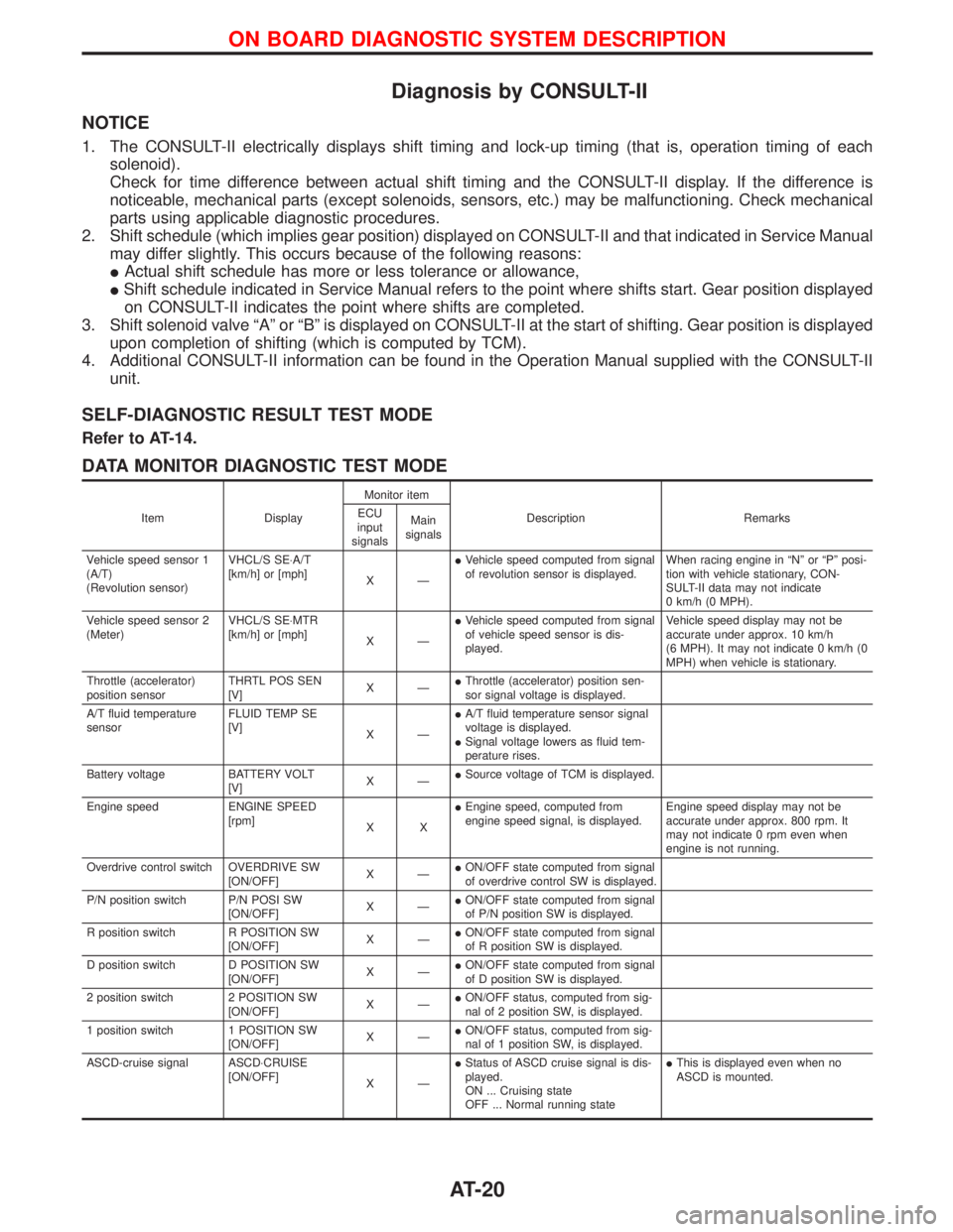
Diagnosis by CONSULT-II
NOTICE
1. The CONSULT-II electrically displays shift timing and lock-up timing (that is, operation timing of each
solenoid).
Check for time difference between actual shift timing and the CONSULT-II display. If the difference is
noticeable, mechanical parts (except solenoids, sensors, etc.) may be malfunctioning. Check mechanical
parts using applicable diagnostic procedures.
2. Shift schedule (which implies gear position) displayed on CONSULT-II and that indicated in Service Manual
may differ slightly. This occurs because of the following reasons:
IActual shift schedule has more or less tolerance or allowance,
IShift schedule indicated in Service Manual refers to the point where shifts start. Gear position displayed
on CONSULT-II indicates the point where shifts are completed.
3. Shift solenoid valve ªAº or ªBº is displayed on CONSULT-II at the start of shifting. Gear position is displayed
upon completion of shifting (which is computed by TCM).
4. Additional CONSULT-II information can be found in the Operation Manual supplied with the CONSULT-II
unit.
SELF-DIAGNOSTIC RESULT TEST MODE
Refer to AT-14.
DATA MONITOR DIAGNOSTIC TEST MODE
Item DisplayMonitor item
Description Remarks ECU
input
signalsMain
signals
Vehicle speed sensor 1
(A/T)
(Revolution sensor)VHCL/S SE×A/T
[km/h] or [mph]
XÐIVehicle speed computed from signal
of revolution sensor is displayed.When racing engine in ªNº or ªPº posi-
tion with vehicle stationary, CON-
SULT-II data may not indicate
0 km/h (0 MPH).
Vehicle speed sensor 2
(Meter)VHCL/S SE×MTR
[km/h] or [mph]
XÐIVehicle speed computed from signal
of vehicle speed sensor is dis-
played.Vehicle speed display may not be
accurate under approx. 10 km/h
(6 MPH). It may not indicate 0 km/h (0
MPH) when vehicle is stationary.
Throttle (accelerator)
position sensorTHRTL POS SEN
[V]XÐIThrottle (accelerator) position sen-
sor signal voltage is displayed.
A/T fluid temperature
sensorFLUID TEMP SE
[V]
XÐIA/T fluid temperature sensor signal
voltage is displayed.
ISignal voltage lowers as fluid tem-
perature rises.
Battery voltage BATTERY VOLT
[V]XÐISource voltage of TCM is displayed.
Engine speed ENGINE SPEED
[rpm]
XXIEngine speed, computed from
engine speed signal, is displayed.Engine speed display may not be
accurate under approx. 800 rpm. It
may not indicate 0 rpm even when
engine is not running.
Overdrive control switch OVERDRIVE SW
[ON/OFF]XÐION/OFF state computed from signal
of overdrive control SW is displayed.
P/N position switch P/N POSI SW
[ON/OFF]XÐION/OFF state computed from signal
of P/N position SW is displayed.
R position switch R POSITION SW
[ON/OFF]XÐION/OFF state computed from signal
of R position SW is displayed.
D position switch D POSITION SW
[ON/OFF]XÐION/OFF state computed from signal
of D position SW is displayed.
2 position switch 2 POSITION SW
[ON/OFF]XÐION/OFF status, computed from sig-
nal of 2 position SW, is displayed.
1 position switch 1 POSITION SW
[ON/OFF]XÐION/OFF status, computed from sig-
nal of 1 position SW, is displayed.
ASCD-cruise signal ASCD×CRUISE
[ON/OFF]
XÐIStatus of ASCD cruise signal is dis-
played.
ON ... Cruising state
OFF ... Normal running stateIThis is displayed even when no
ASCD is mounted.
ON BOARD DIAGNOSTIC SYSTEM DESCRIPTION
AT-20
Page 26 of 1767
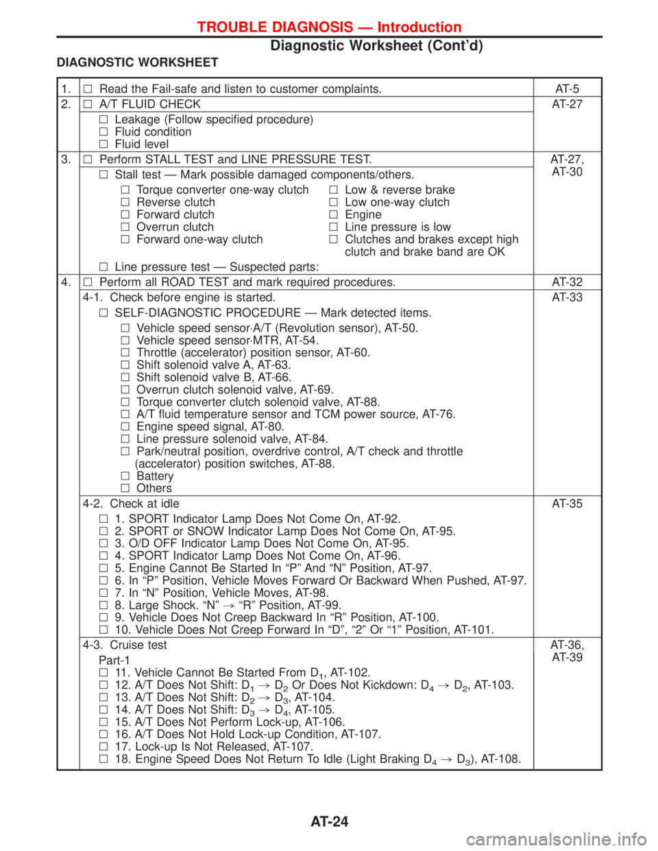
DIAGNOSTIC WORKSHEET
1.lRead the Fail-safe and listen to customer complaints. AT-5
2.lA/T FLUID CHECK AT-27
lLeakage (Follow specified procedure)
lFluid condition
lFluid level
3.lPerform STALL TEST and LINE PRESSURE TEST. AT-27,
AT-30
lStall test Ð Mark possible damaged components/others.
lTorque converter one-way clutch
lReverse clutch
lForward clutch
lOverrun clutch
lForward one-way clutchlLow & reverse brake
lLow one-way clutch
lEngine
lLine pressure is low
lClutches and brakes except high
clutch and brake band are OK
lLine pressure test Ð Suspected parts:
4.lPerform all ROAD TEST and mark required procedures. AT-32
4-1. Check before engine is started. AT-33
lSELF-DIAGNOSTIC PROCEDURE Ð Mark detected items.
lVehicle speed sensor×A/T (Revolution sensor), AT-50.
lVehicle speed sensor×MTR, AT-54.
lThrottle (accelerator) position sensor, AT-60.
lShift solenoid valve A, AT-63.
lShift solenoid valve B, AT-66.
lOverrun clutch solenoid valve, AT-69.
lTorque converter clutch solenoid valve, AT-88.
lA/T fluid temperature sensor and TCM power source, AT-76.
lEngine speed signal, AT-80.
lLine pressure solenoid valve, AT-84.
lPark/neutral position, overdrive control, A/T check and throttle
(accelerator) position switches, AT-88.
lBattery
lOthers
4-2. Check at idle AT-35
l1. SPORT Indicator Lamp Does Not Come On, AT-92.
l2. SPORT or SNOW Indicator Lamp Does Not Come On, AT-95.
l3. O/D OFF Indicator Lamp Does Not Come On, AT-95.
l4. SPORT Indicator Lamp Does Not Come On, AT-96.
l5. Engine Cannot Be Started In ªPº And ªNº Position, AT-97.
l6. In ªPº Position, Vehicle Moves Forward Or Backward When Pushed, AT-97.
l7. In ªNº Position, Vehicle Moves, AT-98.
l8. Large Shock. ªNº,ªRº Position, AT-99.
l9. Vehicle Does Not Creep Backward In ªRº Position, AT-100.
l10. Vehicle Does Not Creep Forward In ªDº, ª2º Or ª1º Position, AT-101.
4-3. Cruise testAT-36,
AT-39
Part-1
l11. Vehicle Cannot Be Started From D
1, AT-102.
l12. A/T Does Not Shift: D
1,D2Or Does Not Kickdown: D4,D2, AT-103.
l13. A/T Does Not Shift: D
2,D3, AT-104.
l14. A/T Does Not Shift: D
3,D4, AT-105.
l15. A/T Does Not Perform Lock-up, AT-106.
l16. A/T Does Not Hold Lock-up Condition, AT-107.
l17. Lock-up Is Not Released, AT-107.
l18. Engine Speed Does Not Return To Idle (Light Braking D
4,D3), AT-108.
TROUBLE DIAGNOSIS Ð Introduction
Diagnostic Worksheet (Cont'd)
AT-24
Page 27 of 1767
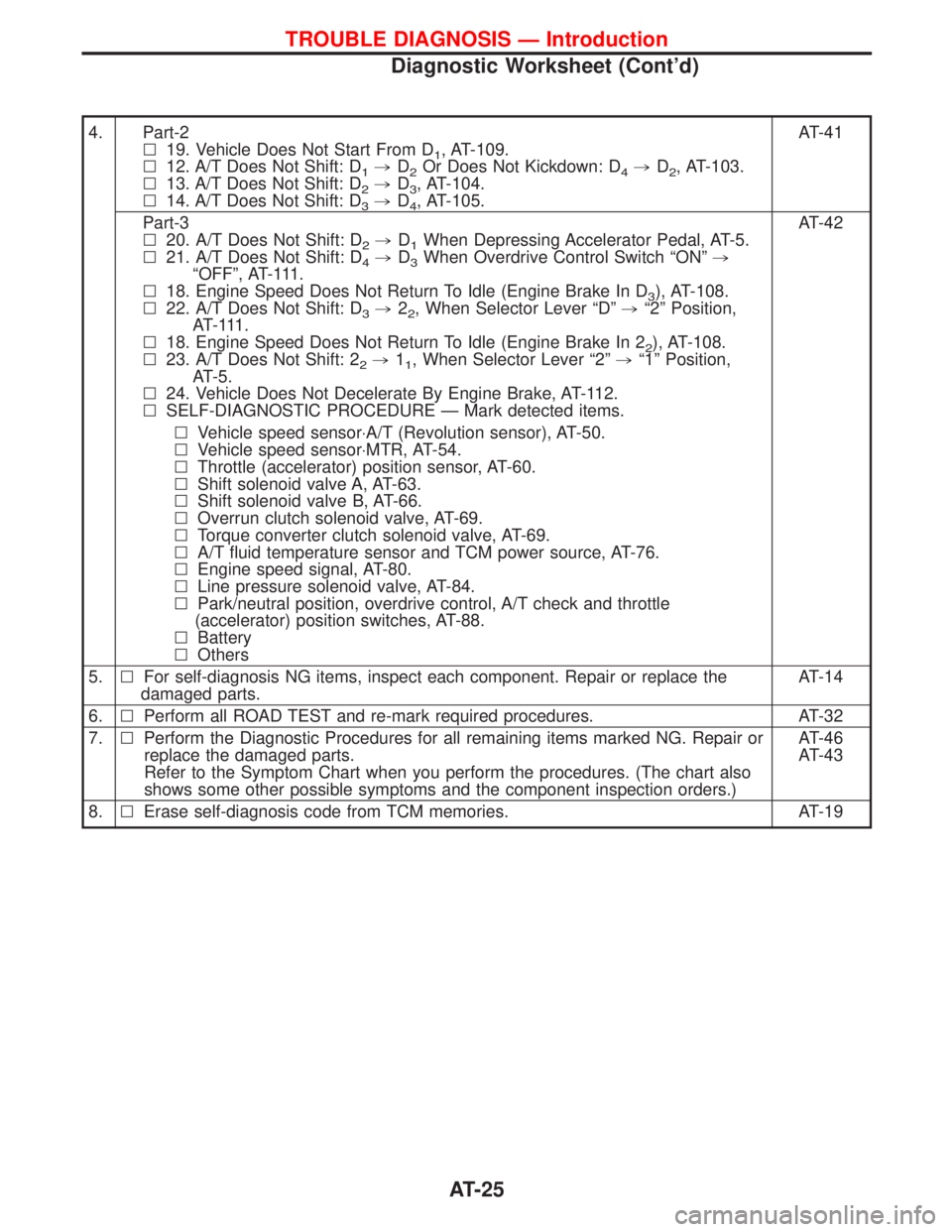
4. Part-2
l19. Vehicle Does Not Start From D
1, AT-109.
l12. A/T Does Not Shift: D
1,D2Or Does Not Kickdown: D4,D2, AT-103.
l13. A/T Does Not Shift: D
2,D3, AT-104.
l14. A/T Does Not Shift: D
3,D4, AT-105.AT-41
Part-3
l20. A/T Does Not Shift: D
2,D1When Depressing Accelerator Pedal, AT-5.
l21. A/T Does Not Shift: D
4,D3When Overdrive Control Switch ªONº,
ªOFFº, AT-111.
l18. Engine Speed Does Not Return To Idle (Engine Brake In D
3), AT-108.
l22. A/T Does Not Shift: D
3,22, When Selector Lever ªDº,ª2º Position,
AT- 111 .
l18. Engine Speed Does Not Return To Idle (Engine Brake In 2
2), AT-108.
l23. A/T Does Not Shift: 2
2,11, When Selector Lever ª2º,ª1º Position,
AT-5.
l24. Vehicle Does Not Decelerate By Engine Brake, AT-112.
lSELF-DIAGNOSTIC PROCEDURE Ð Mark detected items.AT-42
lVehicle speed sensor×A/T (Revolution sensor), AT-50.
lVehicle speed sensor×MTR, AT-54.
lThrottle (accelerator) position sensor, AT-60.
lShift solenoid valve A, AT-63.
lShift solenoid valve B, AT-66.
lOverrun clutch solenoid valve, AT-69.
lTorque converter clutch solenoid valve, AT-69.
lA/T fluid temperature sensor and TCM power source, AT-76.
lEngine speed signal, AT-80.
lLine pressure solenoid valve, AT-84.
lPark/neutral position, overdrive control, A/T check and throttle
(accelerator) position switches, AT-88.
lBattery
lOthers
5.lFor self-diagnosis NG items, inspect each component. Repair or replace the
damaged parts.AT-14
6.lPerform all ROAD TEST and re-mark required procedures. AT-32
7.lPerform the Diagnostic Procedures for all remaining items marked NG. Repair or
replace the damaged parts.
Refer to the Symptom Chart when you perform the procedures. (The chart also
shows some other possible symptoms and the component inspection orders.)AT-46
AT-43
8.lErase self-diagnosis code from TCM memories. AT-19
TROUBLE DIAGNOSIS Ð Introduction
Diagnostic Worksheet (Cont'd)
AT-25
Page 49 of 1767
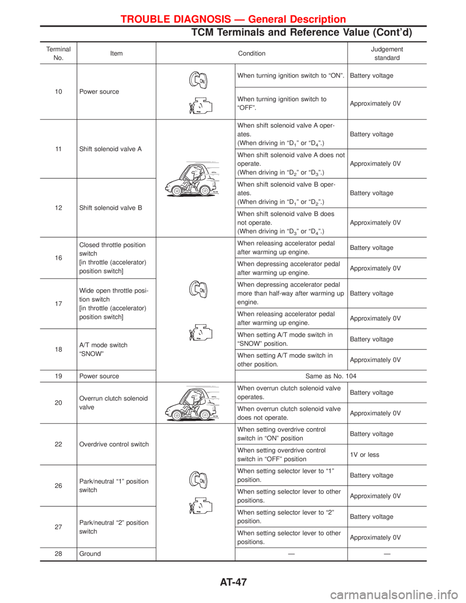
Terminal
No.Item ConditionJudgement
standard
10 Power source
When turning ignition switch to ªONº. Battery voltage
When turning ignition switch to
ªOFFº.Approximately 0V
11 Shift solenoid valve A
When shift solenoid valve A oper-
ates.
(When driving in ªD
1ºorªD4º.)Battery voltage
When shift solenoid valve A does not
operate.
(When driving in ªD
2ºorªD3º.)Approximately 0V
12 Shift solenoid valve BWhen shift solenoid valve B oper-
ates.
(When driving in ªD
1ºorªD2º.)Battery voltage
When shift solenoid valve B does
not operate.
(When driving in ªD
3ºorªD4º.)Approximately 0V
16Closed throttle position
switch
[in throttle (accelerator)
position switch]
When releasing accelerator pedal
after warming up engine.Battery voltage
When depressing accelerator pedal
after warming up engine.Approximately 0V
17Wide open throttle posi-
tion switch
[in throttle (accelerator)
position switch]When depressing accelerator pedal
more than half-way after warming up
engine.Battery voltage
When releasing accelerator pedal
after warming up engine.Approximately 0V
18A/T mode switch
ªSNOWºWhen setting A/T mode switch in
ªSNOWº position.Battery voltage
When setting A/T mode switch in
other position.Approximately 0V
19 Power source Same as No. 104
20Overrun clutch solenoid
valve
When overrun clutch solenoid valve
operates.Battery voltage
When overrun clutch solenoid valve
does not operate.Approximately 0V
22 Overdrive control switch
When setting overdrive control
switch in ªONº positionBattery voltage
When setting overdrive control
switch in ªOFFº position1V or less
26Park/neutral ª1º position
switchWhen setting selector lever to ª1º
position.Battery voltage
When setting selector lever to other
positions.Approximately 0V
27Park/neutral ª2º position
switchWhen setting selector lever to ª2º
position.Battery voltage
When setting selector lever to other
positions.Approximately 0V
28 Ground Ð Ð
TROUBLE DIAGNOSIS Ð General Description
TCM Terminals and Reference Value (Cont'd)
AT-47
Page 50 of 1767
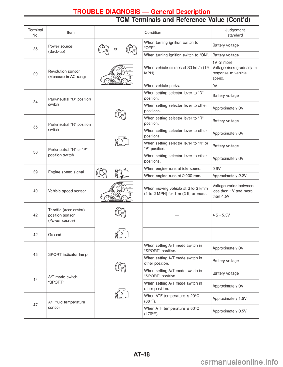
Terminal
No.Item ConditionJudgement
standard
28Power source
(Back-up)
or
When turning ignition switch to
ªOFFº.Battery voltage
When turning ignition switch to ªONº. Battery voltage
29Revolution sensor
(Measure in AC rang)
When vehicle cruises at 30 km/h (19
MPH).1V or more
Voltage rises gradually in
response to vehicle
speed.
When vehicle parks. 0V
34Park/neutral ªDº position
switch
When setting selector lever to ªDº
position.Battery voltage
When setting selector lever to other
positions.Approximately 0V
35Park/neutral ªRº position
switchWhen setting selector lever to ªRº
position.Battery voltage
When setting selector lever to other
positions.Approximately 0V
36Park/neutral ªNº or ªPº
position switchWhen setting selector lever to ªNº or
ªPº position.Battery voltage
When setting selector lever to other
positions.Approximately 0V
39 Engine speed signal
When engine runs at idle speed. 0.8V
When engine runs at 2,000 rpm. Approximately 2.2V
40 Vehicle speed sensor
When moving vehicle at 2 to 3 km/h
(1 to 2 MPH) for1m(3ft)ormore.Voltage varies between
less than 1V and more
than 4.5V
42Throttle (accelerator)
position sensor
(Power source)
Ð 4.5 - 5.5V
42 Ground Ð Ð
43 SPORT indicator lamp
When setting A/T mode switch in
ªSPORTº position.Approximately 0V
When setting A/T mode switch in
other position.Battery voltage
44A/T mode switch
ªSPORTºWhen setting A/T mode switch in
ªSPORTº position.Battery voltage
When setting A/T mode switch in
other position.Approximately 0V
47A/T fluid temperature
sensorWhen ATF temperature is 20ÉC
(68ÉF).Approximately 1.5V
When ATF temperature is 80ÉC
(176ÉF).Approximately 0.5V
TROUBLE DIAGNOSIS Ð General Description
TCM Terminals and Reference Value (Cont'd)
AT-48
Page 66 of 1767
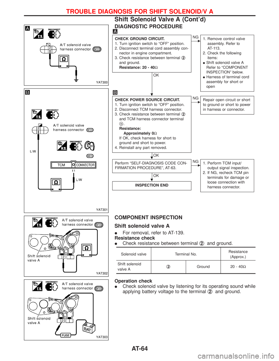
DIAGNOSTIC PROCEDURE
CHECK GROUND CIRCUIT.
1. Turn ignition switch to ªOFFº position.
2. Disconnect terminal cord assembly con-
nector in engine compartment.
3. Check resistance between terminalq
2
and ground.
Resistance: 20 - 40W
OK
ENG
1. Remove control valve
assembly. Refer to
AT-113.
2. Check the following
items:
IShift solenoid valve A
Refer to ªCOMPONENT
INSPECTIONº below.
IHarness of terminal cord
assembly for short or
open
CHECK POWER SOURCE CIRCUIT.
1. Turn ignition switch to ªOFFº position.
2. Disconnect TCM harness connector.
3. Check resistance between terminalq
2
and TCM harness connector terminal
q
11.
Resistance:
Approximately 0W
If OK, check harness for short to
ground and short to power.
4. Reinstall any part removed.
OK
ENG
Repair open circuit or short
to ground or short to power
in harness or connector.
Perform ªSELF-DIAGNOSIS CODE CON-
FIRMATION PROCEDUREº, AT-63.
OK
ENG
1. Perform TCM input/
output signal inspection.
2. If NG, recheck TCM pin
terminals for damage or
loose connection with
harness connector.
INSPECTION END
COMPONENT INSPECTION
Shift solenoid valve A
IFor removal, refer to AT-139.
Resistance check
ICheck resistance between terminalq
2and ground.
Solenoid valve Terminal No.Resistance
(Approx.)
Shift solenoid
valve Aq
2Ground 20 - 40W
Operation check
ICheck solenoid valve by listening for its operating sound while
applying battery voltage to the terminalq
2and ground.
YAT300
YAT301
YAT302
YAT303
H
H
H
TROUBLE DIAGNOSIS FOR SHIFT SOLENOID/V A
Shift Solenoid Valve A (Cont'd)
AT-64
Page 69 of 1767
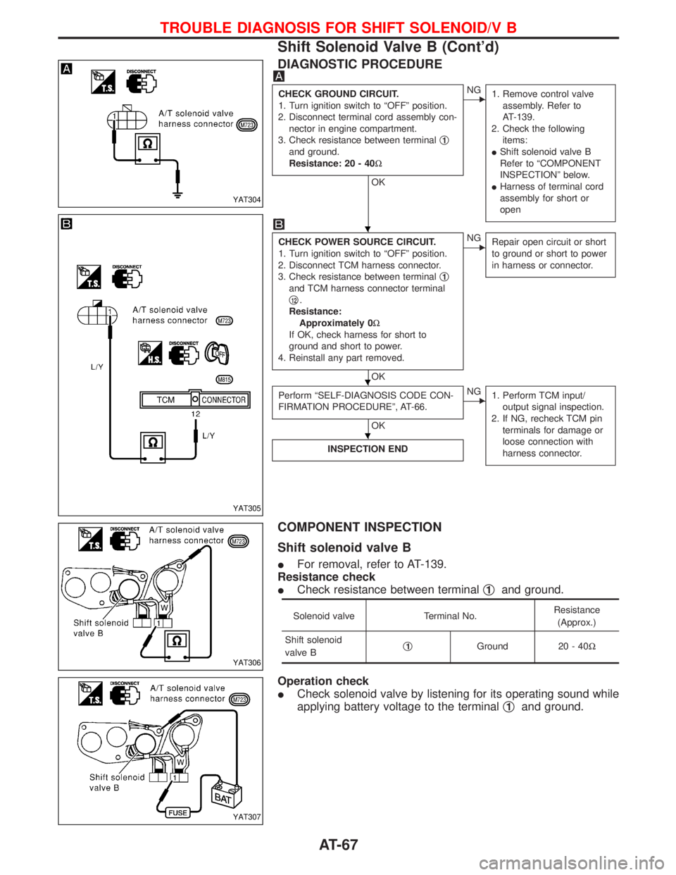
DIAGNOSTIC PROCEDURE
CHECK GROUND CIRCUIT.
1. Turn ignition switch to ªOFFº position.
2. Disconnect terminal cord assembly con-
nector in engine compartment.
3. Check resistance between terminalq
1
and ground.
Resistance: 20 - 40W
OK
ENG
1. Remove control valve
assembly. Refer to
AT-139.
2. Check the following
items:
IShift solenoid valve B
Refer to ªCOMPONENT
INSPECTIONº below.
IHarness of terminal cord
assembly for short or
open
CHECK POWER SOURCE CIRCUIT.
1. Turn ignition switch to ªOFFº position.
2. Disconnect TCM harness connector.
3. Check resistance between terminalq
1
and TCM harness connector terminal
q
12.
Resistance:
Approximately 0W
If OK, check harness for short to
ground and short to power.
4. Reinstall any part removed.
OK
ENG
Repair open circuit or short
to ground or short to power
in harness or connector.
Perform ªSELF-DIAGNOSIS CODE CON-
FIRMATION PROCEDUREº, AT-66.
OK
ENG
1. Perform TCM input/
output signal inspection.
2. If NG, recheck TCM pin
terminals for damage or
loose connection with
harness connector.
INSPECTION END
COMPONENT INSPECTION
Shift solenoid valve B
IFor removal, refer to AT-139.
Resistance check
ICheck resistance between terminalq
1and ground.
Solenoid valve Terminal No.Resistance
(Approx.)
Shift solenoid
valve Bq
1Ground 20 - 40W
Operation check
ICheck solenoid valve by listening for its operating sound while
applying battery voltage to the terminalq
1and ground.
YAT304
YAT305
YAT306
YAT307
H
H
H
TROUBLE DIAGNOSIS FOR SHIFT SOLENOID/V B
Shift Solenoid Valve B (Cont'd)
AT-67
Page 72 of 1767
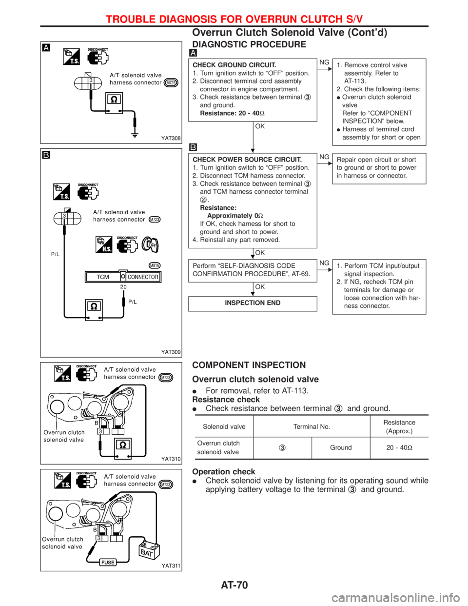
DIAGNOSTIC PROCEDURE
CHECK GROUND CIRCUIT.
1. Turn ignition switch to ªOFFº position.
2. Disconnect terminal cord assembly
connector in engine compartment.
3. Check resistance between terminalq
3
and ground.
Resistance: 20 - 40W
OK
ENG
1. Remove control valve
assembly. Refer to
AT-113.
2. Check the following items:
IOverrun clutch solenoid
valve
Refer to ªCOMPONENT
INSPECTIONº below.
IHarness of terminal cord
assembly for short or open
CHECK POWER SOURCE CIRCUIT.
1. Turn ignition switch to ªOFFº position.
2. Disconnect TCM harness connector.
3. Check resistance between terminalq
3
and TCM harness connector terminal
q
20.
Resistance:
Approximately 0W
If OK, check harness for short to
ground and short to power.
4. Reinstall any part removed.
OK
ENG
Repair open circuit or short
to ground or short to power
in harness or connector.
Perform ªSELF-DIAGNOSIS CODE
CONFIRMATION PROCEDUREº, AT-69.
OK
ENG
1. Perform TCM input/output
signal inspection.
2. If NG, recheck TCM pin
terminals for damage or
loose connection with har-
ness connector.
INSPECTION END
COMPONENT INSPECTION
Overrun clutch solenoid valve
IFor removal, refer to AT-113.
Resistance check
ICheck resistance between terminalq
3and ground.
Solenoid valve Terminal No.Resistance
(Approx.)
Overrun clutch
solenoid valveq
3Ground 20 - 40W
Operation check
ICheck solenoid valve by listening for its operating sound while
applying battery voltage to the terminalq
3and ground.
YAT308
YAT309
YAT310
YAT311
H
H
H
TROUBLE DIAGNOSIS FOR OVERRUN CLUTCH S/V
Overrun Clutch Solenoid Valve (Cont'd)
AT-70
Page 76 of 1767
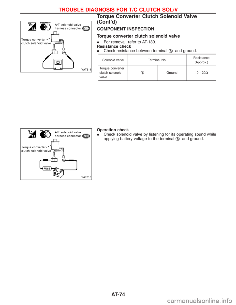
COMPONENT INSPECTION
Torque converter clutch solenoid valve
IFor removal, refer to AT-139.
Resistance check
ICheck resistance between terminalq
6and ground.
Solenoid valve Terminal No.Resistance
(Approx.)
Torque converter
clutch solenoid
valveq
6Ground 10 - 20W
Operation check
ICheck solenoid valve by listening for its operating sound while
applying battery voltage to the terminalq
6and ground.
YAT314
YAT315
TROUBLE DIAGNOSIS FOR T/C CLUTCH SOL/V
Torque Converter Clutch Solenoid Valve
(Cont'd)
AT-74