turn signal NISSAN TERRANO 2002 Service Repair Manual
[x] Cancel search | Manufacturer: NISSAN, Model Year: 2002, Model line: TERRANO, Model: NISSAN TERRANO 2002Pages: 1767, PDF Size: 41.51 MB
Page 16 of 1767
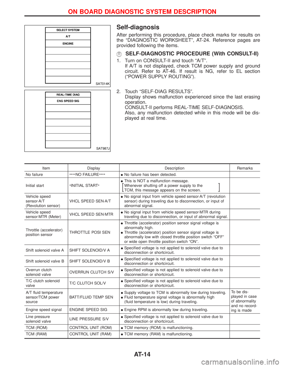
Self-diagnosis
After performing this procedure, place check marks for results on
the ªDIAGNOSTIC WORKSHEETº, AT-24. Reference pages are
provided following the items.
SELF-DIAGNOSTIC PROCEDURE (With CONSULT-II)
1. Turn on CONSULT-II and touch ªA/Tº.
If A/T is not displayed, check TCM power supply and ground
circuit. Refer to AT-46. If result is NG, refer to EL section
(ªPOWER SUPPLY ROUTINGº).
2. Touch ªSELF-DIAG RESULTSº.
Display shows malfunction experienced since the last erasing
operation.
CONSULT-II performs REAL-TIME SELF-DIAGNOSIS.
Also, any malfunction detected while in this mode will be dis-
played at real time.
Item Display Description Remarks
No failure
****NO FAILURE
****INo failure has been detected.
Initial start
*INITIAL START
*IThis is NOT a malfunction message.
Whenever shutting off a power supply to the
TCM, this message appears on the screen.
[]
Vehicle speed
sensor×A/T
(Revolution sensor)VHCL SPEED SEN×A/TINo signal input from vehicle speed sensor×A/T (revolution
sensor) during traveling due to disconnection, or input of
abnormal signal.
Vehicle speed
sensor×MTR (Meter)VHCL SPEED SEN×MTRINo signal input from vehicle speed sensor×MTR during
traveling due to disconnection, or input of abnormal signal.
Throttle (accelerator)
position sensorTHROTTLE POSI SENIThrottle (accelerator) position sensor signal voltage is
abnormally high.
IThrottle (accelerator) position sensor signal voltage is
abnormally low with closed throttle position switch ªOFFº
or wide open throttle position switch ªONº.
Shift solenoid valve A SHIFT SOLENOID/V AISpecified voltage is not applied to solenoid valve due to
disconnection or shortcircuit.
Shift solenoid valve B SHIFT SOLENOID/V BISpecified voltage is not applied to solenoid valve due to
disconnection or shortcircuit.
Overrun clutch
solenoid valveOVERRUN CLUTCH S/VISpecified voltage is not applied to solenoid valve due to
disconnection or shortcircuit.
T/C clutch solenoid
valveT/C CLUTCH SOL/VISpecified voltage is not applied to solenoid valve due to
disconnection or shortcircuit.
A/T fluid temperature
sensor/TCM power
sourceBATT/FLUID TEMP SENISupply voltage to TCM is abnormally low during traveling.
IFluid temperature signal voltage is abnormally high
(fluid temperature is low) during traveling.To be dis-
played in case
of abnormality
and no record-
ing is made Engine speed signal ENGINE SPEED SIGIEngine RPM is abnormally low during traveling.
Line pressure
solenoid valveLINE PRESSURE S/VISpecified voltage is not applied to solenoid valve due to
disconnection or shortcircuit.
TCM (ROM) CONTROL UNIT (ROM)ITCM memory (ROM) is malfunctioning.
TCM (RAM) CONTROL UNIT (RAM)ITCM memory (RAM) is malfunctioning.
SAT014K
SAT987J
ON BOARD DIAGNOSTIC SYSTEM DESCRIPTION
AT-14
Page 26 of 1767
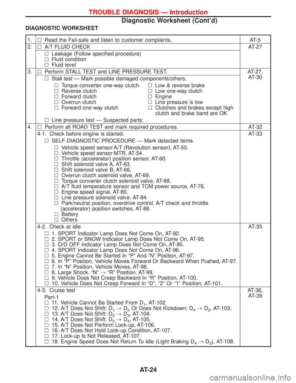
DIAGNOSTIC WORKSHEET
1.lRead the Fail-safe and listen to customer complaints. AT-5
2.lA/T FLUID CHECK AT-27
lLeakage (Follow specified procedure)
lFluid condition
lFluid level
3.lPerform STALL TEST and LINE PRESSURE TEST. AT-27,
AT-30
lStall test Ð Mark possible damaged components/others.
lTorque converter one-way clutch
lReverse clutch
lForward clutch
lOverrun clutch
lForward one-way clutchlLow & reverse brake
lLow one-way clutch
lEngine
lLine pressure is low
lClutches and brakes except high
clutch and brake band are OK
lLine pressure test Ð Suspected parts:
4.lPerform all ROAD TEST and mark required procedures. AT-32
4-1. Check before engine is started. AT-33
lSELF-DIAGNOSTIC PROCEDURE Ð Mark detected items.
lVehicle speed sensor×A/T (Revolution sensor), AT-50.
lVehicle speed sensor×MTR, AT-54.
lThrottle (accelerator) position sensor, AT-60.
lShift solenoid valve A, AT-63.
lShift solenoid valve B, AT-66.
lOverrun clutch solenoid valve, AT-69.
lTorque converter clutch solenoid valve, AT-88.
lA/T fluid temperature sensor and TCM power source, AT-76.
lEngine speed signal, AT-80.
lLine pressure solenoid valve, AT-84.
lPark/neutral position, overdrive control, A/T check and throttle
(accelerator) position switches, AT-88.
lBattery
lOthers
4-2. Check at idle AT-35
l1. SPORT Indicator Lamp Does Not Come On, AT-92.
l2. SPORT or SNOW Indicator Lamp Does Not Come On, AT-95.
l3. O/D OFF Indicator Lamp Does Not Come On, AT-95.
l4. SPORT Indicator Lamp Does Not Come On, AT-96.
l5. Engine Cannot Be Started In ªPº And ªNº Position, AT-97.
l6. In ªPº Position, Vehicle Moves Forward Or Backward When Pushed, AT-97.
l7. In ªNº Position, Vehicle Moves, AT-98.
l8. Large Shock. ªNº,ªRº Position, AT-99.
l9. Vehicle Does Not Creep Backward In ªRº Position, AT-100.
l10. Vehicle Does Not Creep Forward In ªDº, ª2º Or ª1º Position, AT-101.
4-3. Cruise testAT-36,
AT-39
Part-1
l11. Vehicle Cannot Be Started From D
1, AT-102.
l12. A/T Does Not Shift: D
1,D2Or Does Not Kickdown: D4,D2, AT-103.
l13. A/T Does Not Shift: D
2,D3, AT-104.
l14. A/T Does Not Shift: D
3,D4, AT-105.
l15. A/T Does Not Perform Lock-up, AT-106.
l16. A/T Does Not Hold Lock-up Condition, AT-107.
l17. Lock-up Is Not Released, AT-107.
l18. Engine Speed Does Not Return To Idle (Light Braking D
4,D3), AT-108.
TROUBLE DIAGNOSIS Ð Introduction
Diagnostic Worksheet (Cont'd)
AT-24
Page 27 of 1767
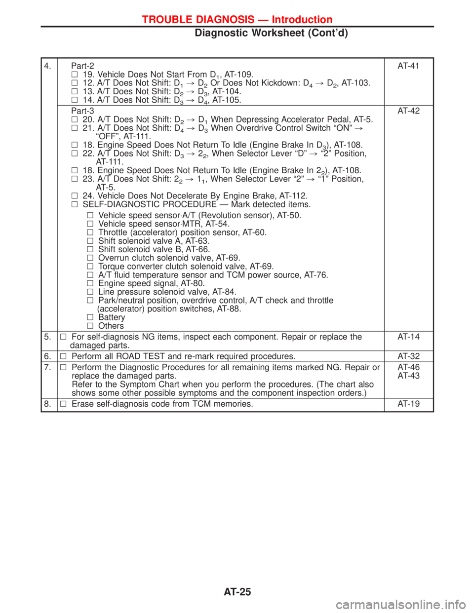
4. Part-2
l19. Vehicle Does Not Start From D
1, AT-109.
l12. A/T Does Not Shift: D
1,D2Or Does Not Kickdown: D4,D2, AT-103.
l13. A/T Does Not Shift: D
2,D3, AT-104.
l14. A/T Does Not Shift: D
3,D4, AT-105.AT-41
Part-3
l20. A/T Does Not Shift: D
2,D1When Depressing Accelerator Pedal, AT-5.
l21. A/T Does Not Shift: D
4,D3When Overdrive Control Switch ªONº,
ªOFFº, AT-111.
l18. Engine Speed Does Not Return To Idle (Engine Brake In D
3), AT-108.
l22. A/T Does Not Shift: D
3,22, When Selector Lever ªDº,ª2º Position,
AT- 111 .
l18. Engine Speed Does Not Return To Idle (Engine Brake In 2
2), AT-108.
l23. A/T Does Not Shift: 2
2,11, When Selector Lever ª2º,ª1º Position,
AT-5.
l24. Vehicle Does Not Decelerate By Engine Brake, AT-112.
lSELF-DIAGNOSTIC PROCEDURE Ð Mark detected items.AT-42
lVehicle speed sensor×A/T (Revolution sensor), AT-50.
lVehicle speed sensor×MTR, AT-54.
lThrottle (accelerator) position sensor, AT-60.
lShift solenoid valve A, AT-63.
lShift solenoid valve B, AT-66.
lOverrun clutch solenoid valve, AT-69.
lTorque converter clutch solenoid valve, AT-69.
lA/T fluid temperature sensor and TCM power source, AT-76.
lEngine speed signal, AT-80.
lLine pressure solenoid valve, AT-84.
lPark/neutral position, overdrive control, A/T check and throttle
(accelerator) position switches, AT-88.
lBattery
lOthers
5.lFor self-diagnosis NG items, inspect each component. Repair or replace the
damaged parts.AT-14
6.lPerform all ROAD TEST and re-mark required procedures. AT-32
7.lPerform the Diagnostic Procedures for all remaining items marked NG. Repair or
replace the damaged parts.
Refer to the Symptom Chart when you perform the procedures. (The chart also
shows some other possible symptoms and the component inspection orders.)AT-46
AT-43
8.lErase self-diagnosis code from TCM memories. AT-19
TROUBLE DIAGNOSIS Ð Introduction
Diagnostic Worksheet (Cont'd)
AT-25
Page 50 of 1767
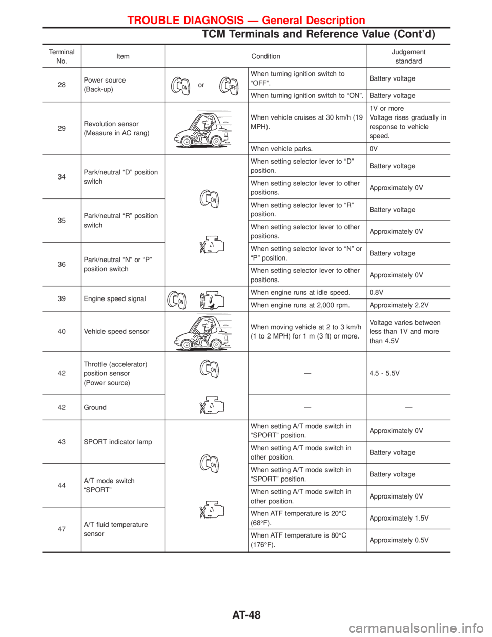
Terminal
No.Item ConditionJudgement
standard
28Power source
(Back-up)
or
When turning ignition switch to
ªOFFº.Battery voltage
When turning ignition switch to ªONº. Battery voltage
29Revolution sensor
(Measure in AC rang)
When vehicle cruises at 30 km/h (19
MPH).1V or more
Voltage rises gradually in
response to vehicle
speed.
When vehicle parks. 0V
34Park/neutral ªDº position
switch
When setting selector lever to ªDº
position.Battery voltage
When setting selector lever to other
positions.Approximately 0V
35Park/neutral ªRº position
switchWhen setting selector lever to ªRº
position.Battery voltage
When setting selector lever to other
positions.Approximately 0V
36Park/neutral ªNº or ªPº
position switchWhen setting selector lever to ªNº or
ªPº position.Battery voltage
When setting selector lever to other
positions.Approximately 0V
39 Engine speed signal
When engine runs at idle speed. 0.8V
When engine runs at 2,000 rpm. Approximately 2.2V
40 Vehicle speed sensor
When moving vehicle at 2 to 3 km/h
(1 to 2 MPH) for1m(3ft)ormore.Voltage varies between
less than 1V and more
than 4.5V
42Throttle (accelerator)
position sensor
(Power source)
Ð 4.5 - 5.5V
42 Ground Ð Ð
43 SPORT indicator lamp
When setting A/T mode switch in
ªSPORTº position.Approximately 0V
When setting A/T mode switch in
other position.Battery voltage
44A/T mode switch
ªSPORTºWhen setting A/T mode switch in
ªSPORTº position.Battery voltage
When setting A/T mode switch in
other position.Approximately 0V
47A/T fluid temperature
sensorWhen ATF temperature is 20ÉC
(68ÉF).Approximately 1.5V
When ATF temperature is 80ÉC
(176ÉF).Approximately 0.5V
TROUBLE DIAGNOSIS Ð General Description
TCM Terminals and Reference Value (Cont'd)
AT-48
Page 63 of 1767
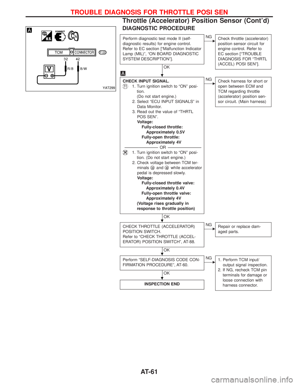
DIAGNOSTIC PROCEDURE
Perform diagnostic test mode II (self-
diagnostic results) for engine control.
Refer to EC section [ªMalfunction Indicator
Lamp (MIL)º, ªON BOARD DIAGNOSTIC
SYSTEM DESCRIPTIONº].
OK
ENG
Check throttle (accelerator)
position sensor circuit for
engine control. Refer to
EC section [ªTROUBLE
DIAGNOSIS FOR ªTHRTL
(ACCEL) POSI SENº].
CHECK INPUT SIGNAL.
1. Turn ignition switch to ªONº posi-
tion.
(Do not start engine.)
2. Select ªECU INPUT SIGNALSº in
Data Monitor.
3. Read out the value of ªTHRTL
POS SENº.
Voltage:
Fully-closed throttle:
Approximately 0.5V
Fully-open throttle:
Approximately 4V
-----------------------------------------------------------------------------------------------------------------------OR -----------------------------------------------------------------------------------------------------------------------
1. Turn ignition switch to ªONº posi-
tion. (Do not start engine.)
2. Check voltage between TCM ter-
minalsq
32andq42while accelerator
pedal is depressed slowly.
Voltage:
Fully-closed throttle valve:
Approximately 0.4V
Fully-open throttle valve:
Approximately 4V
(Voltage rises gradually in
response to throttle position)
OK
ENG
Check harness for short or
open between ECM and
TCM regarding throttle
(accelerator) position sen-
sor circuit. (Main harness)
CHECK THROTTLE (ACCELERATOR)
POSITION SWITCH.
Refer to ªCHECK THROTTLE (ACCEL-
ERATOR) POSITION SWITCHº, AT-88.
OK
ENG
Repair or replace dam-
aged parts.
Perform ªSELF-DIAGNOSIS CODE CON-
FIRMATION PROCEDUREº, AT-60.
OK
ENG
1. Perform TCM input/
output signal inspection.
2. If NG, recheck TCM pin
terminals for damage or
loose connection with
harness connector.
INSPECTION END
YAT299
H
H
H
H
TROUBLE DIAGNOSIS FOR THROTTLE POSI SEN
Throttle (Accelerator) Position Sensor (Cont'd)
AT-61
Page 65 of 1767
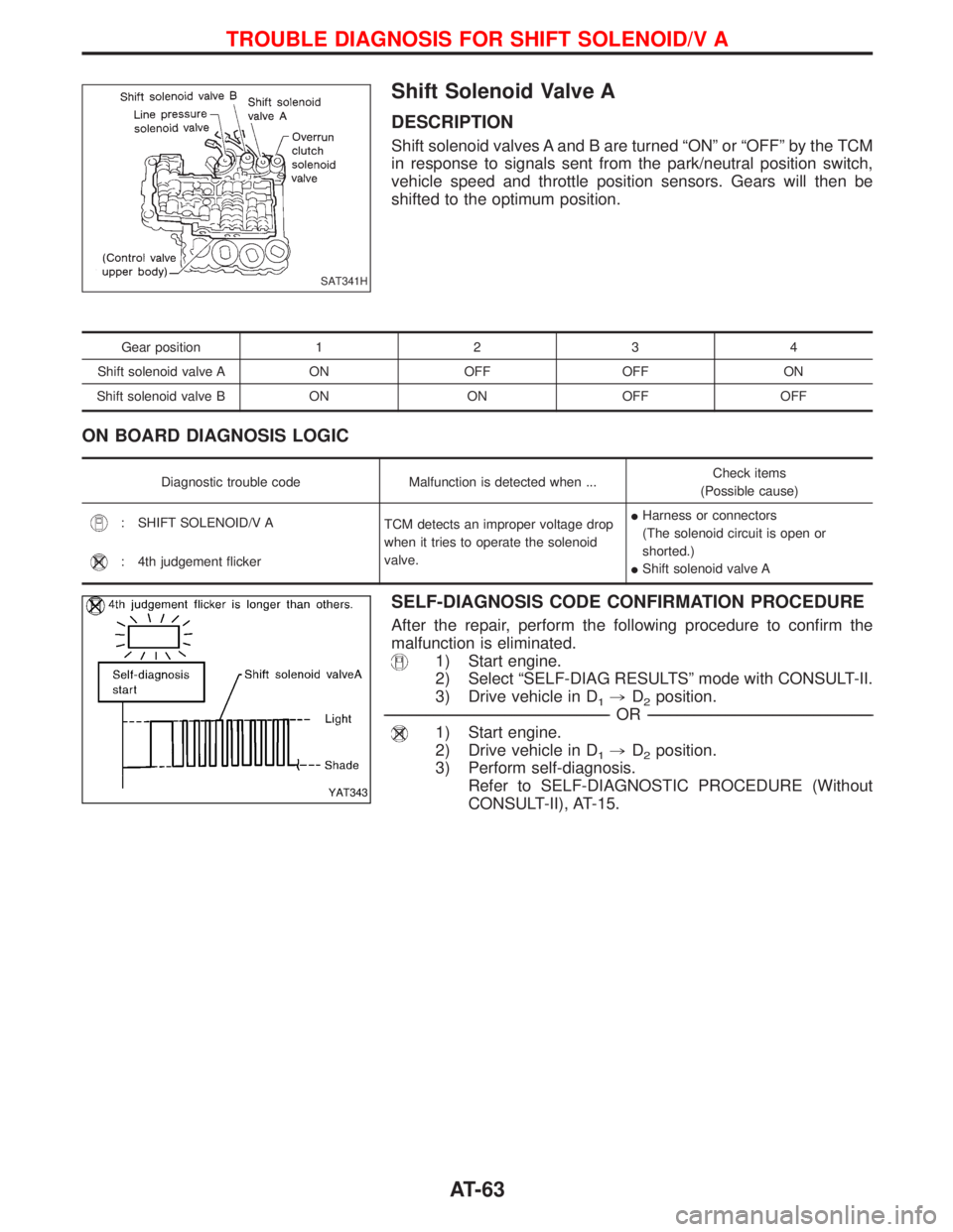
Shift Solenoid Valve A
DESCRIPTION
Shift solenoid valves A and B are turned ªONº or ªOFFº by the TCM
in response to signals sent from the park/neutral position switch,
vehicle speed and throttle position sensors. Gears will then be
shifted to the optimum position.
Gear position1234
Shift solenoid valve A ON OFF OFF ON
Shift solenoid valve B ON ON OFF OFF
ON BOARD DIAGNOSIS LOGIC
Diagnostic trouble code Malfunction is detected when ...Check items
(Possible cause)
: SHIFT SOLENOID/V A
TCM detects an improper voltage drop
when it tries to operate the solenoid
valve.IHarness or connectors
(The solenoid circuit is open or
shorted.)
IShift solenoid valve A
: 4th judgement flicker
SELF-DIAGNOSIS CODE CONFIRMATION PROCEDURE
After the repair, perform the following procedure to confirm the
malfunction is eliminated.
1) Start engine.
2) Select ªSELF-DIAG RESULTSº mode with CONSULT-II.
3) Drive vehicle in D
1,D2position.
------------------------------------------------------------------------------------------------------------------------------------------------------------------------------------------------------------------------------------------------------------OR------------------------------------------------------------------------------------------------------------------------------------------------------------------------------------------------------------------------------------------------------------
1) Start engine.
2) Drive vehicle in D
1,D2position.
3) Perform self-diagnosis.
Refer to SELF-DIAGNOSTIC PROCEDURE (Without
CONSULT-II), AT-15.
SAT341H
YAT343
TROUBLE DIAGNOSIS FOR SHIFT SOLENOID/V A
AT-63
Page 66 of 1767
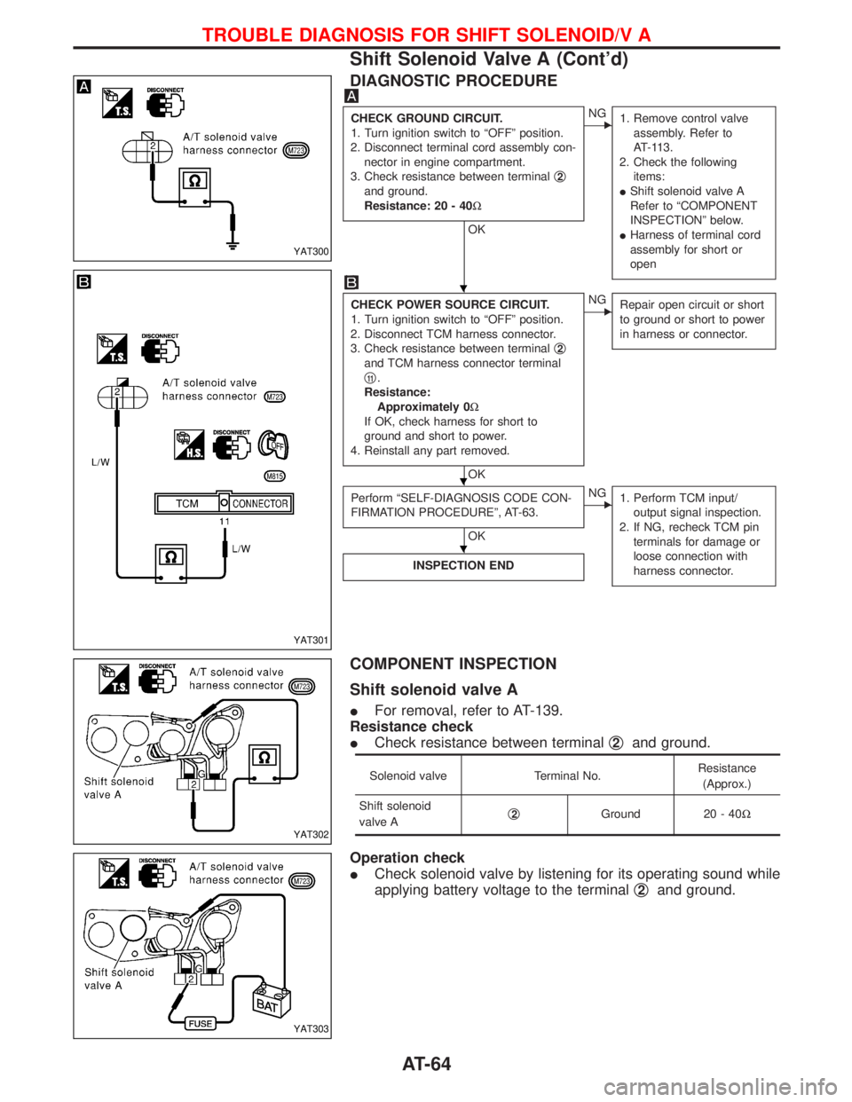
DIAGNOSTIC PROCEDURE
CHECK GROUND CIRCUIT.
1. Turn ignition switch to ªOFFº position.
2. Disconnect terminal cord assembly con-
nector in engine compartment.
3. Check resistance between terminalq
2
and ground.
Resistance: 20 - 40W
OK
ENG
1. Remove control valve
assembly. Refer to
AT-113.
2. Check the following
items:
IShift solenoid valve A
Refer to ªCOMPONENT
INSPECTIONº below.
IHarness of terminal cord
assembly for short or
open
CHECK POWER SOURCE CIRCUIT.
1. Turn ignition switch to ªOFFº position.
2. Disconnect TCM harness connector.
3. Check resistance between terminalq
2
and TCM harness connector terminal
q
11.
Resistance:
Approximately 0W
If OK, check harness for short to
ground and short to power.
4. Reinstall any part removed.
OK
ENG
Repair open circuit or short
to ground or short to power
in harness or connector.
Perform ªSELF-DIAGNOSIS CODE CON-
FIRMATION PROCEDUREº, AT-63.
OK
ENG
1. Perform TCM input/
output signal inspection.
2. If NG, recheck TCM pin
terminals for damage or
loose connection with
harness connector.
INSPECTION END
COMPONENT INSPECTION
Shift solenoid valve A
IFor removal, refer to AT-139.
Resistance check
ICheck resistance between terminalq
2and ground.
Solenoid valve Terminal No.Resistance
(Approx.)
Shift solenoid
valve Aq
2Ground 20 - 40W
Operation check
ICheck solenoid valve by listening for its operating sound while
applying battery voltage to the terminalq
2and ground.
YAT300
YAT301
YAT302
YAT303
H
H
H
TROUBLE DIAGNOSIS FOR SHIFT SOLENOID/V A
Shift Solenoid Valve A (Cont'd)
AT-64
Page 68 of 1767
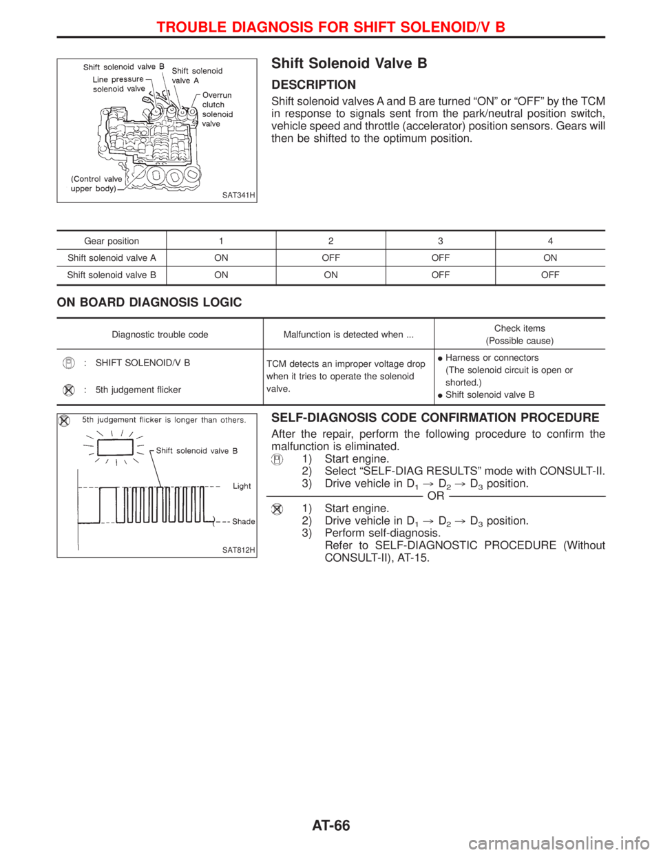
Shift Solenoid Valve B
DESCRIPTION
Shift solenoid valves A and B are turned ªONº or ªOFFº by the TCM
in response to signals sent from the park/neutral position switch,
vehicle speed and throttle (accelerator) position sensors. Gears will
then be shifted to the optimum position.
Gear position1234
Shift solenoid valve A ON OFF OFF ON
Shift solenoid valve B ON ON OFF OFF
ON BOARD DIAGNOSIS LOGIC
Diagnostic trouble code Malfunction is detected when ...Check items
(Possible cause)
: SHIFT SOLENOID/V B
TCM detects an improper voltage drop
when it tries to operate the solenoid
valve.IHarness or connectors
(The solenoid circuit is open or
shorted.)
IShift solenoid valve B
: 5th judgement flicker
SELF-DIAGNOSIS CODE CONFIRMATION PROCEDURE
After the repair, perform the following procedure to confirm the
malfunction is eliminated.
1) Start engine.
2) Select ªSELF-DIAG RESULTSº mode with CONSULT-II.
3) Drive vehicle in D
1,D2,D3position.
------------------------------------------------------------------------------------------------------------------------------------------------------------------------------------------------------------------------------------------------------------OR------------------------------------------------------------------------------------------------------------------------------------------------------------------------------------------------------------------------------------------------------------
1) Start engine.
2) Drive vehicle in D
1,D2,D3position.
3) Perform self-diagnosis.
Refer to SELF-DIAGNOSTIC PROCEDURE (Without
CONSULT-II), AT-15.
SAT341H
SAT812H
TROUBLE DIAGNOSIS FOR SHIFT SOLENOID/V B
AT-66
Page 69 of 1767
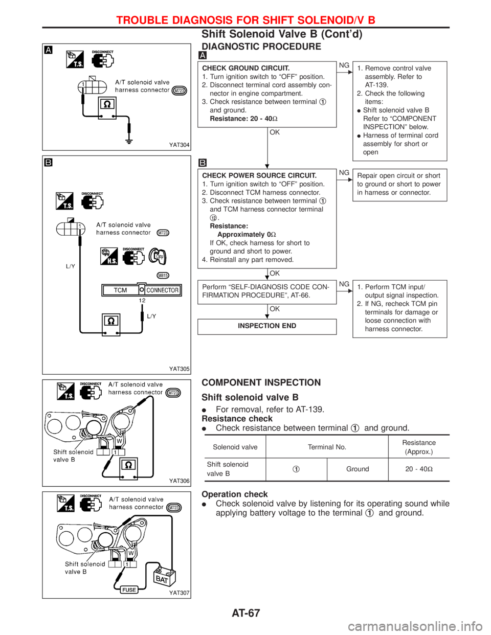
DIAGNOSTIC PROCEDURE
CHECK GROUND CIRCUIT.
1. Turn ignition switch to ªOFFº position.
2. Disconnect terminal cord assembly con-
nector in engine compartment.
3. Check resistance between terminalq
1
and ground.
Resistance: 20 - 40W
OK
ENG
1. Remove control valve
assembly. Refer to
AT-139.
2. Check the following
items:
IShift solenoid valve B
Refer to ªCOMPONENT
INSPECTIONº below.
IHarness of terminal cord
assembly for short or
open
CHECK POWER SOURCE CIRCUIT.
1. Turn ignition switch to ªOFFº position.
2. Disconnect TCM harness connector.
3. Check resistance between terminalq
1
and TCM harness connector terminal
q
12.
Resistance:
Approximately 0W
If OK, check harness for short to
ground and short to power.
4. Reinstall any part removed.
OK
ENG
Repair open circuit or short
to ground or short to power
in harness or connector.
Perform ªSELF-DIAGNOSIS CODE CON-
FIRMATION PROCEDUREº, AT-66.
OK
ENG
1. Perform TCM input/
output signal inspection.
2. If NG, recheck TCM pin
terminals for damage or
loose connection with
harness connector.
INSPECTION END
COMPONENT INSPECTION
Shift solenoid valve B
IFor removal, refer to AT-139.
Resistance check
ICheck resistance between terminalq
1and ground.
Solenoid valve Terminal No.Resistance
(Approx.)
Shift solenoid
valve Bq
1Ground 20 - 40W
Operation check
ICheck solenoid valve by listening for its operating sound while
applying battery voltage to the terminalq
1and ground.
YAT304
YAT305
YAT306
YAT307
H
H
H
TROUBLE DIAGNOSIS FOR SHIFT SOLENOID/V B
Shift Solenoid Valve B (Cont'd)
AT-67
Page 72 of 1767
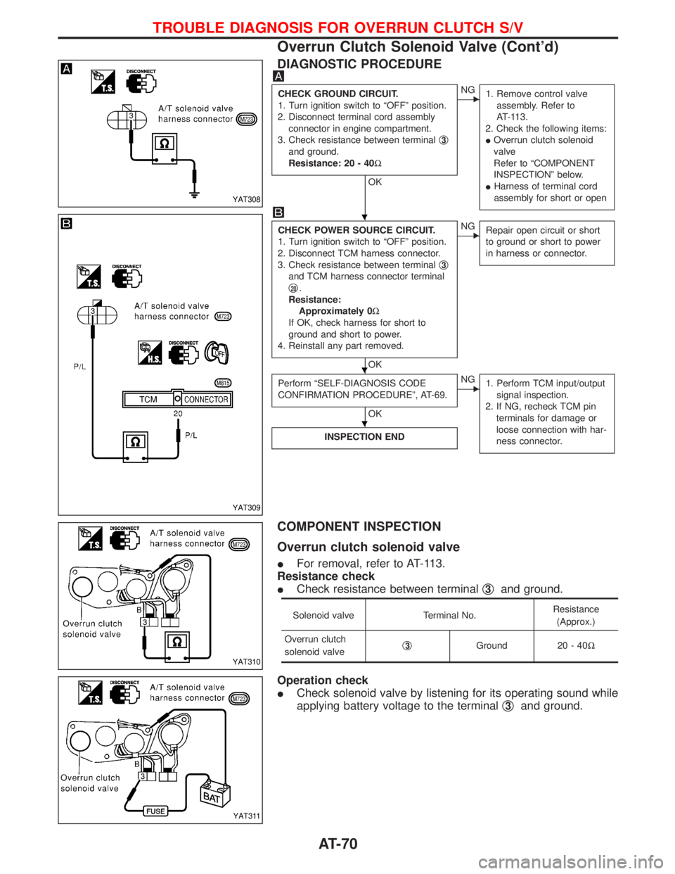
DIAGNOSTIC PROCEDURE
CHECK GROUND CIRCUIT.
1. Turn ignition switch to ªOFFº position.
2. Disconnect terminal cord assembly
connector in engine compartment.
3. Check resistance between terminalq
3
and ground.
Resistance: 20 - 40W
OK
ENG
1. Remove control valve
assembly. Refer to
AT-113.
2. Check the following items:
IOverrun clutch solenoid
valve
Refer to ªCOMPONENT
INSPECTIONº below.
IHarness of terminal cord
assembly for short or open
CHECK POWER SOURCE CIRCUIT.
1. Turn ignition switch to ªOFFº position.
2. Disconnect TCM harness connector.
3. Check resistance between terminalq
3
and TCM harness connector terminal
q
20.
Resistance:
Approximately 0W
If OK, check harness for short to
ground and short to power.
4. Reinstall any part removed.
OK
ENG
Repair open circuit or short
to ground or short to power
in harness or connector.
Perform ªSELF-DIAGNOSIS CODE
CONFIRMATION PROCEDUREº, AT-69.
OK
ENG
1. Perform TCM input/output
signal inspection.
2. If NG, recheck TCM pin
terminals for damage or
loose connection with har-
ness connector.
INSPECTION END
COMPONENT INSPECTION
Overrun clutch solenoid valve
IFor removal, refer to AT-113.
Resistance check
ICheck resistance between terminalq
3and ground.
Solenoid valve Terminal No.Resistance
(Approx.)
Overrun clutch
solenoid valveq
3Ground 20 - 40W
Operation check
ICheck solenoid valve by listening for its operating sound while
applying battery voltage to the terminalq
3and ground.
YAT308
YAT309
YAT310
YAT311
H
H
H
TROUBLE DIAGNOSIS FOR OVERRUN CLUTCH S/V
Overrun Clutch Solenoid Valve (Cont'd)
AT-70