suspension NISSAN TERRANO 2002 Service Repair Manual
[x] Cancel search | Manufacturer: NISSAN, Model Year: 2002, Model line: TERRANO, Model: NISSAN TERRANO 2002Pages: 1767, PDF Size: 41.51 MB
Page 1 of 1767
Edition: February 2002
Release: February 2002 (01)
Publication No.: SM2E00-1R20E0E
GENERAL INFORMATIONGI
MAINTENANCEMA
ENGINE MECHANICALEM
ENGINE LUBRICATION &
COOLING SYSTEMSLC
ENGINE CONTROL SYSTEMEC
ACCELERATOR CONTROL,
FUEL & EXHAUST SYSTEMFE
CLUTCHCL
MANUAL TRANSMISSIONMT
AUTOMATIC TRANSMISSIONAT
TRANSFERTF
PROPELLER SHAFT &
DIFFERENTIAL CARRIERPD
FRONT AXLE & FRONT SUSPENSIONFA
REAR AXLE & REAR SUSPENSIONRA
BRAKE SYSTEMBR
STEERING SYSTEMST
RESTRAINT SYSTEMRS
BODY & TRIMBT
HEATER & AIR CONDITIONERHA
STARTING & CHARGING SYSTEMSSC
ELECTRICAL SYSTEMEL
ALPHABETICAL INDEXIDX
TERRANO
MODEL R20 SERIES
NISSAN EUROPE N.V.
NISSAN EUROPE N.V.
Produced in The Netherlands
QUICK REFERENCE INDEX
Page 232 of 1767
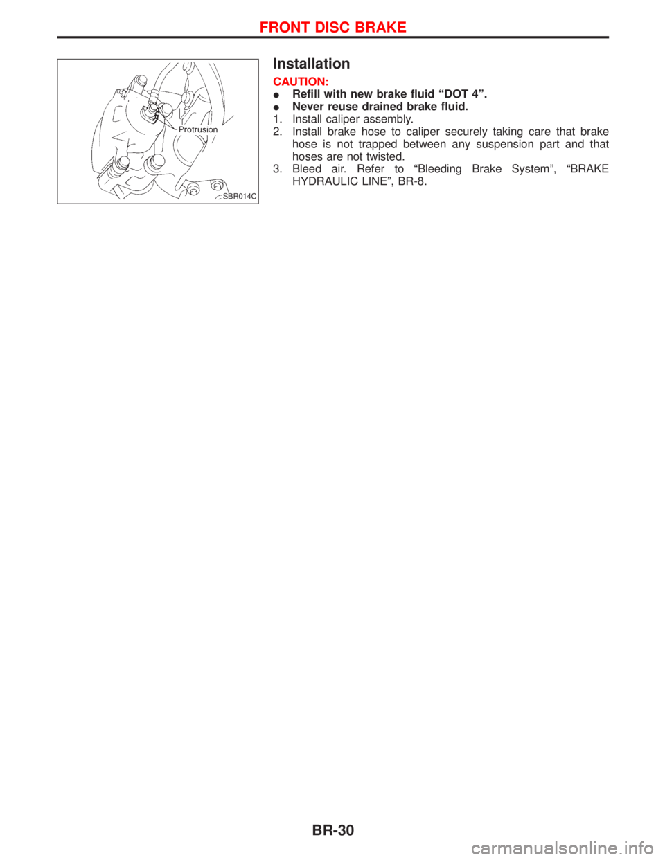
Installation
CAUTION:
IRefill with new brake fluid ªDOT 4º.
INever reuse drained brake fluid.
1. Install caliper assembly.
2. Install brake hose to caliper securely taking care that brake
hose is not trapped between any suspension part and that
hoses are not twisted.
3. Bleed air. Refer to ªBleeding Brake Systemº, ªBRAKE
HYDRAULIC LINEº, BR-8.
SBR014C
FRONT DISC BRAKE
BR-30
Page 1259 of 1767
FRONT AXLE & FRONT SUSPENSION
SECTION
FA
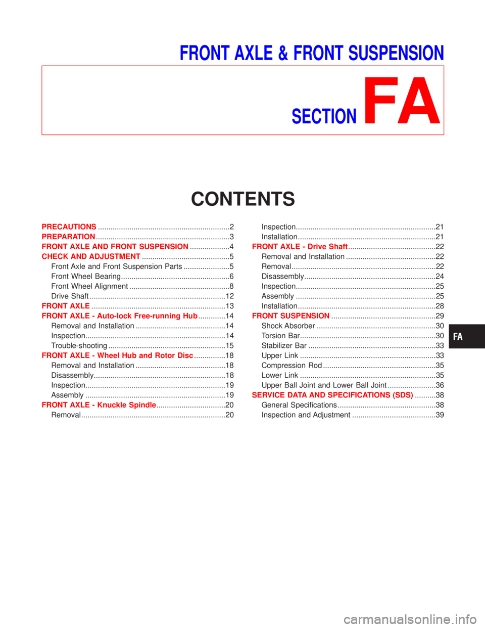
CONTENTS
PRECAUTIONS...............................................................2
PREPARATION................................................................3
FRONT AXLE AND FRONT SUSPENSION...................4
CHECK AND ADJUSTMENT..........................................5
Front Axle and Front Suspension Parts ......................5
Front Wheel Bearing....................................................6
Front Wheel Alignment ................................................8
Drive Shaft .................................................................12
FRONT AXLE................................................................13
FRONT AXLE - Auto-lock Free-running Hub.............14
Removal and Installation ...........................................14
Inspection...................................................................14
Trouble-shooting ........................................................15
FRONT AXLE - Wheel Hub and Rotor Disc...............18
Removal and Installation ...........................................18
Disassembly...............................................................18
Inspection...................................................................19
Assembly ...................................................................19
FRONT AXLE - Knuckle Spindle.................................20
Removal .....................................................................20Inspection...................................................................21
Installation ..................................................................21
FRONT AXLE - Drive Shaft..........................................22
Removal and Installation ...........................................22
Removal .....................................................................22
Disassembly...............................................................24
Inspection...................................................................25
Assembly ...................................................................25
Installation ..................................................................28
FRONT SUSPENSION..................................................29
Shock Absorber .........................................................30
Torsion Bar.................................................................30
Stabilizer Bar .............................................................33
Upper Link .................................................................33
Compression Rod ......................................................35
Lower Link .................................................................35
Upper Ball Joint and Lower Ball Joint .......................36
SERVICE DATA AND SPECIFICATIONS (SDS)..........38
General Specifications ...............................................38
Inspection and Adjustment ........................................39
Page 1260 of 1767
(1) When installing each rubber part, final tightening must be car-
ried out under unladen condition * with tires on ground.
* Fuel, radiator coolant and engine oil full. Spare tire, jack,
hand tools and mats in designated positions.
(2) When removing each suspension part, check wheel alignment
and adjust if necessary.
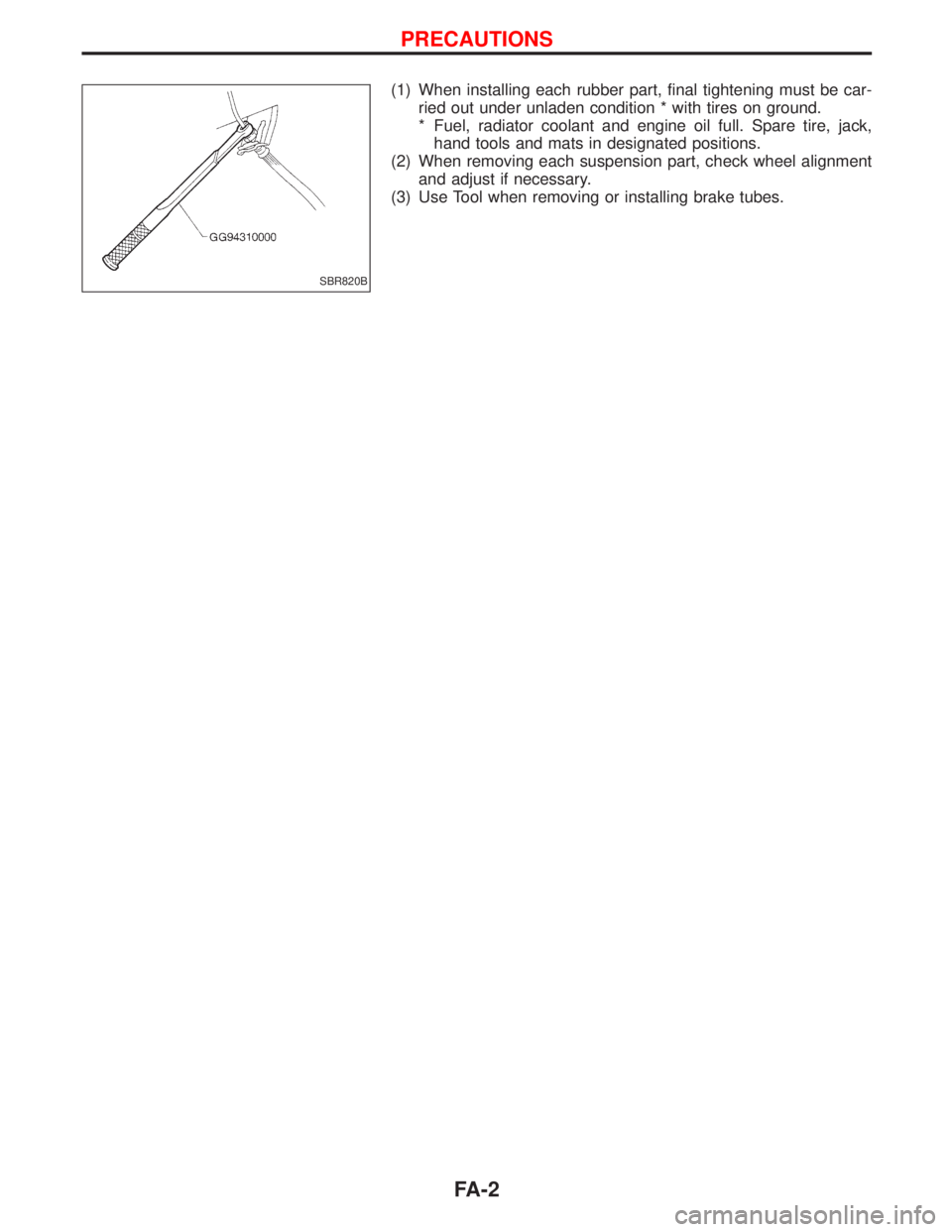
(3) Use Tool when removing or installing brake tubes.
SBR820B
PRECAUTIONS
FA-2
Page 1262 of 1767
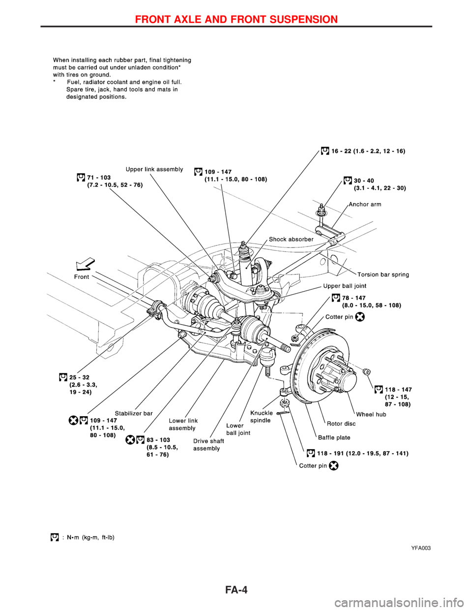
YFA003
FRONT AXLE AND FRONT SUSPENSION
FA-4
Page 1263 of 1767
Front Axle and Front Suspension Parts
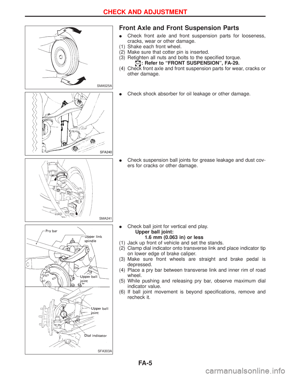
ICheck front axle and front suspension parts for looseness,
cracks, wear or other damage.
(1) Shake each front wheel.
(2) Make sure that cotter pin is inserted.
(3) Retighten all nuts and bolts to the specified torque.
: Refer to ªFRONT SUSPENSIONº, FA-29.
(4) Check front axle and front suspension parts for wear, cracks or
other damage.
ICheck shock absorber for oil leakage or other damage.
ICheck suspension ball joints for grease leakage and dust cov-
ers for cracks or other damage.
ICheck ball joint for vertical end play.
Upper ball joint:
1.6 mm (0.063 in) or less
(1) Jack up front of vehicle and set the stands.
(2) Clamp dial indicator onto transverse link and place indicator tip
on lower edge of brake caliper.
(3) Make sure front wheels are straight and brake pedal is
depressed.
(4) Place a pry bar between transverse link and inner rim of road
wheel.
(5) While pushing and releasing pry bar, observe maximum dial
indicator value.
(6) If ball joint movement is beyond specifications, remove and
recheck it.
SMA525A
SFA240
SMA241
SFA303A
CHECK AND ADJUSTMENT
FA-5
Page 1264 of 1767
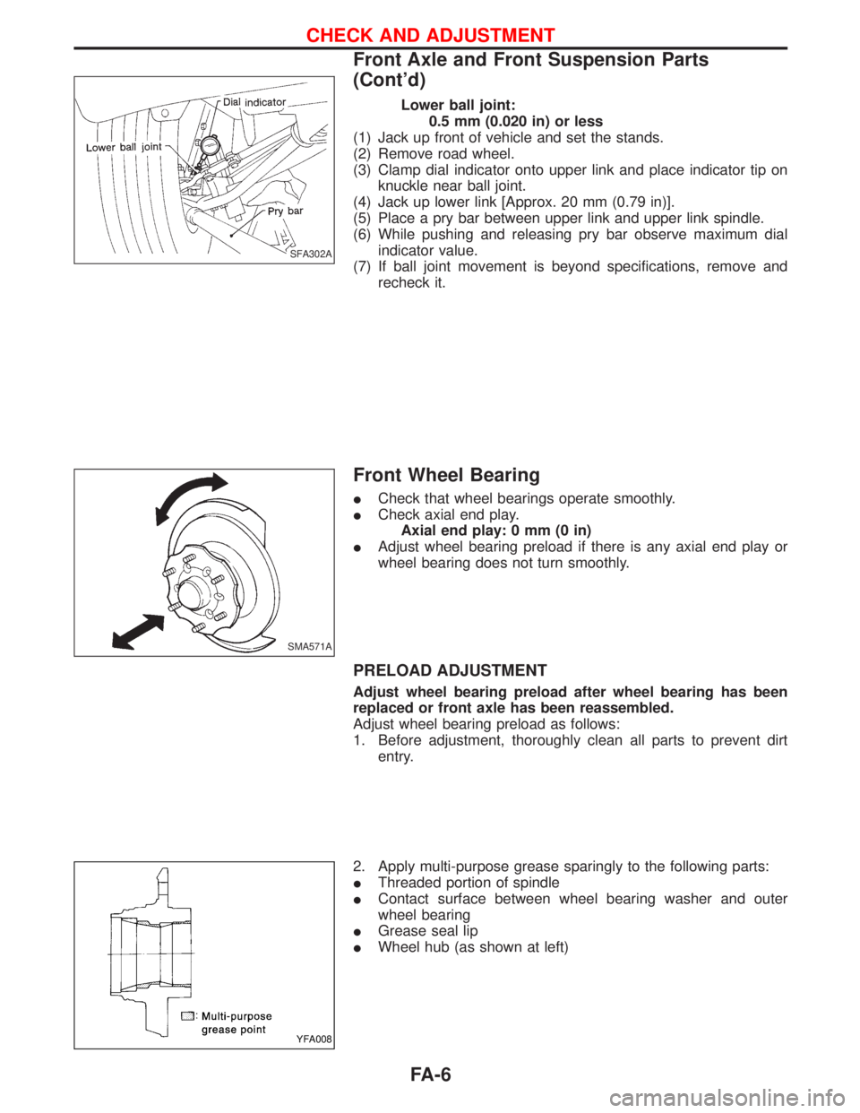
Lower ball joint:
0.5 mm (0.020 in) or less
(1) Jack up front of vehicle and set the stands.
(2) Remove road wheel.
(3) Clamp dial indicator onto upper link and place indicator tip on
knuckle near ball joint.
(4) Jack up lower link [Approx. 20 mm (0.79 in)].
(5) Place a pry bar between upper link and upper link spindle.
(6) While pushing and releasing pry bar observe maximum dial
indicator value.
(7) If ball joint movement is beyond specifications, remove and
recheck it.
Front Wheel Bearing
ICheck that wheel bearings operate smoothly.
ICheck axial end play.
Axial end play: 0 mm (0 in)
IAdjust wheel bearing preload if there is any axial end play or
wheel bearing does not turn smoothly.
PRELOAD ADJUSTMENT
Adjust wheel bearing preload after wheel bearing has been
replaced or front axle has been reassembled.
Adjust wheel bearing preload as follows:
1. Before adjustment, thoroughly clean all parts to prevent dirt
entry.
2. Apply multi-purpose grease sparingly to the following parts:
IThreaded portion of spindle
IContact surface between wheel bearing washer and outer
wheel bearing
IGrease seal lip
IWheel hub (as shown at left)
SFA302A
SMA571A
YFA008
CHECK AND ADJUSTMENT
Front Axle and Front Suspension Parts
(Cont'd)
FA-6
Page 1266 of 1767
Front Wheel Alignment
Before checking front wheel alignment, be sure to make a prelimi-
nary inspection.
PRELIMINARY INSPECTION
1. Check the tires for wear and proper inflation.
2. Check the wheel runout.
Wheel runout:
Refer to SDS, FA-39.
3. Check the front wheel bearings for looseness.
4. Check the front suspension for looseness.
5. Check the steering linkage for looseness.
6. Check that the front shock absorbers work properly by using
the standard bounce test.
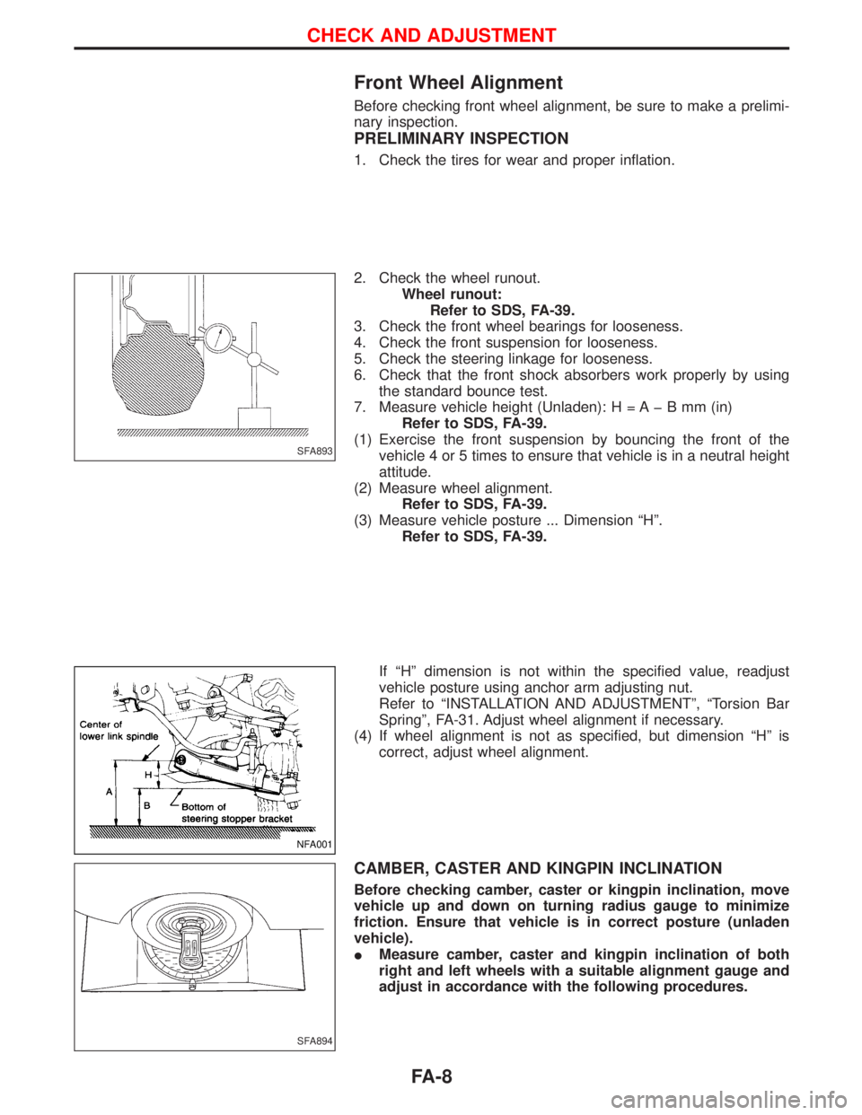
7. Measure vehicle height (Unladen): H = A þ B mm (in)
Refer to SDS, FA-39.
(1) Exercise the front suspension by bouncing the front of the
vehicle 4 or 5 times to ensure that vehicle is in a neutral height
attitude.
(2) Measure wheel alignment.
Refer to SDS, FA-39.
(3) Measure vehicle posture ... Dimension ªHº.
Refer to SDS, FA-39.
If ªHº dimension is not within the specified value, readjust
vehicle posture using anchor arm adjusting nut.
Refer to ªINSTALLATION AND ADJUSTMENTº, ªTorsion Bar
Springº, FA-31. Adjust wheel alignment if necessary.
(4) If wheel alignment is not as specified, but dimension ªHº is
correct, adjust wheel alignment.
CAMBER, CASTER AND KINGPIN INCLINATION
Before checking camber, caster or kingpin inclination, move
vehicle up and down on turning radius gauge to minimize
friction. Ensure that vehicle is in correct posture (unladen
vehicle).
IMeasure camber, caster and kingpin inclination of both
right and left wheels with a suitable alignment gauge and
adjust in accordance with the following procedures.
SFA893
NFA001
SFA894
CHECK AND ADJUSTMENT
FA-8
Page 1287 of 1767
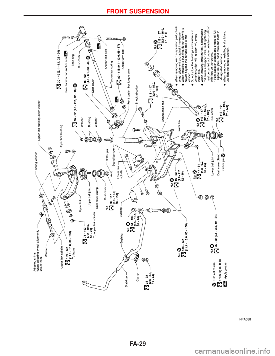
NFA038
FRONT SUSPENSION
FA-29
Page 1288 of 1767
Shock Absorber
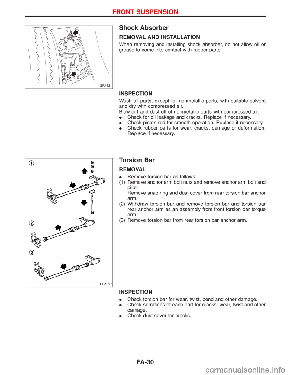
REMOVAL AND INSTALLATION
When removing and installing shock absorber, do not allow oil or
grease to come into contact with rubber parts.
INSPECTION
Wash all parts, except for nonmetallic parts, with suitable solvent
and dry with compressed air.
Blow dirt and dust off of nonmetallic parts with compressed air.
ICheck for oil leakage and cracks. Replace if necessary.
ICheck piston rod for smooth operation. Replace if necessary.
ICheck rubber parts for wear, cracks, damage or deformation.
Replace if necessary.
Torsion Bar
REMOVAL
IRemove torsion bar as follows:
(1) Remove anchor arm bolt nuts and remove anchor arm bolt and
pilot.
Remove snap ring and dust cover from rear torsion bar anchor
arm.
(2) Withdraw torsion bar and remove torsion bar and torsion bar
rear anchor arm as an assembly from front torsion bar torque
arm.
(3) Remove torsion bar from rear torsion bar anchor arm.
INSPECTION
ICheck torsion bar for wear, twist, bend and other damage.
ICheck serrations of each part for cracks, wear, twist and other
damage.
ICheck dust cover for cracks.
SFA931
EFA017
FRONT SUSPENSION
FA-30