low beam NISSAN TERRANO 2002 Service Repair Manual
[x] Cancel search | Manufacturer: NISSAN, Model Year: 2002, Model line: TERRANO, Model: NISSAN TERRANO 2002Pages: 1767, PDF Size: 41.51 MB
Page 845 of 1767
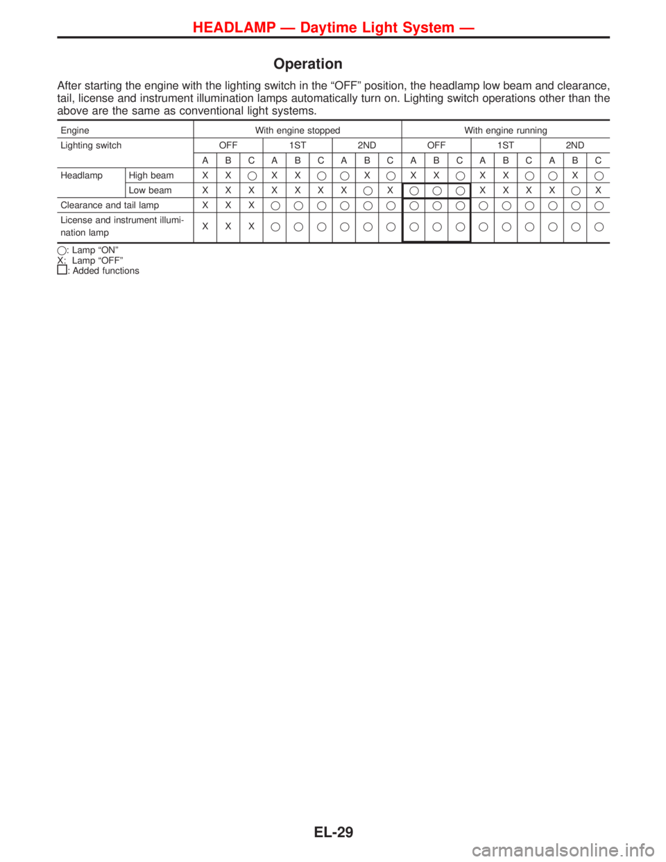
Operation
After starting the engine with the lighting switch in the ªOFFº position, the headlamp low beam and clearance,
tail, license and instrument illumination lamps automatically turn on. Lighting switch operations other than the
above are the same as conventional light systems.
Engine With engine stopped With engine running
Lighting switch OFF 1ST 2ND OFF 1ST 2ND
ABCABCABCABCABCABC
Headlamp High beam X XqXXqqXqXXqXXqqXq
Low beamXXXXXXXqXqqqXXXXqX
Clearance and tail lamp X X Xqqqqqqqqqqqqqqq
License and instrument illumi-
nation lampXXXqqqqqqqqqqqqqqq
q: Lamp ªONº
X: Lamp ªOFFº
: Added functions
HEADLAMP Ð Daytime Light System Ð
EL-29
Page 859 of 1767
Bulb Replacement
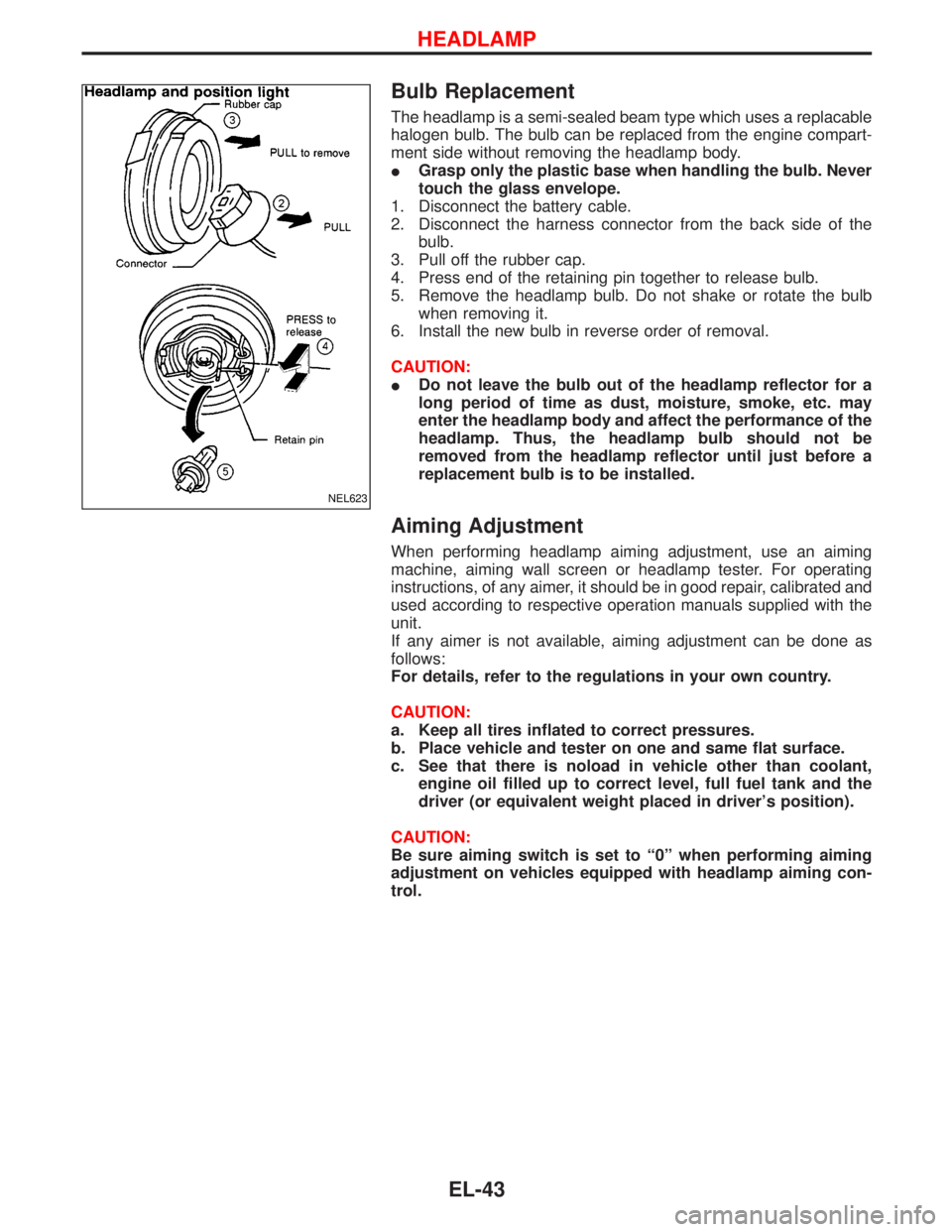
The headlamp is a semi-sealed beam type which uses a replacable
halogen bulb. The bulb can be replaced from the engine compart-
ment side without removing the headlamp body.
IGrasp only the plastic base when handling the bulb. Never
touch the glass envelope.
1. Disconnect the battery cable.
2. Disconnect the harness connector from the back side of the
bulb.
3. Pull off the rubber cap.
4. Press end of the retaining pin together to release bulb.
5. Remove the headlamp bulb. Do not shake or rotate the bulb
when removing it.
6. Install the new bulb in reverse order of removal.
CAUTION:
IDo not leave the bulb out of the headlamp reflector for a
long period of time as dust, moisture, smoke, etc. may
enter the headlamp body and affect the performance of the
headlamp. Thus, the headlamp bulb should not be
removed from the headlamp reflector until just before a
replacement bulb is to be installed.
Aiming Adjustment
When performing headlamp aiming adjustment, use an aiming
machine, aiming wall screen or headlamp tester. For operating
instructions, of any aimer, it should be in good repair, calibrated and
used according to respective operation manuals supplied with the
unit.
If any aimer is not available, aiming adjustment can be done as
follows:
For details, refer to the regulations in your own country.
CAUTION:
a. Keep all tires inflated to correct pressures.
b. Place vehicle and tester on one and same flat surface.
c. See that there is noload in vehicle other than coolant,
engine oil filled up to correct level, full fuel tank and the
driver (or equivalent weight placed in driver's position).
CAUTION:
Be sure aiming switch is set to ª0º when performing aiming
adjustment on vehicles equipped with headlamp aiming con-
trol.
NEL623
HEADLAMP
EL-43
Page 860 of 1767
LOW BEAM
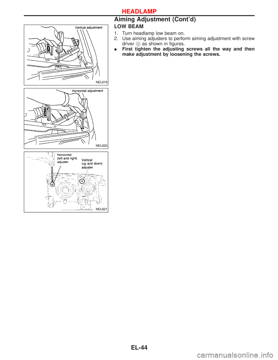
1. Turn headlamp low beam on.
2. Use aiming adjusters to perform aiming adjustment with screw
driver!as shown in figures.
IFirst tighten the adjusting screws all the way and then
make adjustment by loosening the screws.
NEL619
NEL620
NEL621
HEADLAMP
Aiming Adjustment (Cont'd)
EL-44
Page 869 of 1767
Front Fog Lamp Aiming Adjustment
When performing fog lamp aiming adjustment, use an aiming
machine, aiming wall screen or headlamp tester. The aimer should
be in good operational condition, calibrated and used according to
the relevant operation manuals supplied with the unit.
If an aimer is not available, aiming adjustment can be done as fol-
lows:
For details, refer to the regulations in your own country.
CAUTION:
IKeep all tires inflated to correct pressures.
IPlace vehicle and tester on one and the same flat surface.
IEnsure that there is no-load in the vehicle other than
coolant, engine oil (filled up to correct level), full fuel tank
and the driver (or equivalent weight placed in driver's posi-
tion).
For details of front fog lamp aiming adjustment, refer to ªAiming
Adjustmentº, EL-43.
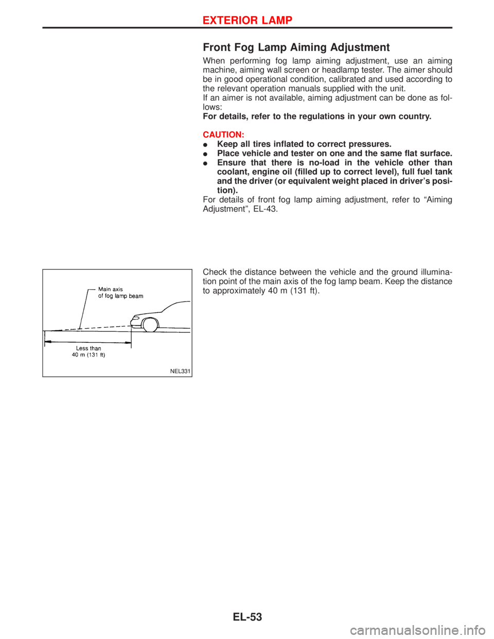
Check the distance between the vehicle and the ground illumina-
tion point of the main axis of the fog lamp beam. Keep the distance
to approximately 40 m (131 ft).
NEL331
EXTERIOR LAMP
EL-53
Page 876 of 1767
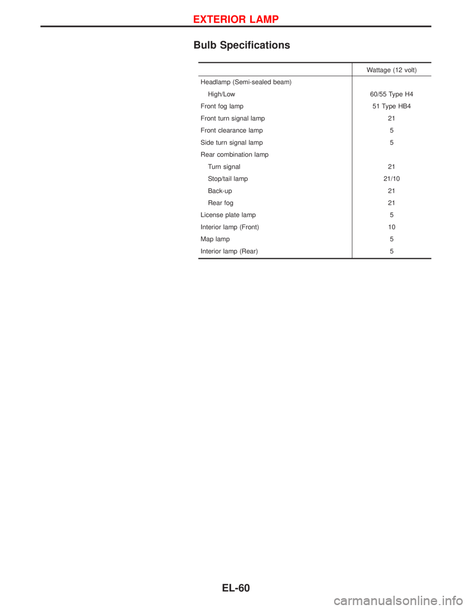
Bulb Specifications
Wattage (12 volt)
Headlamp (Semi-sealed beam)
High/Low 60/55 Type H4
Front fog lamp 51 Type HB4
Front turn signal lamp 21
Front clearance lamp 5
Side turn signal lamp 5
Rear combination lamp
Turn signal 21
Stop/tail lamp 21/10
Back-up 21
Rear fog 21
License plate lamp 5
Interior lamp (Front) 10
Map lamp 5
Interior lamp (Rear) 5
EXTERIOR LAMP
EL-60
Page 1178 of 1767
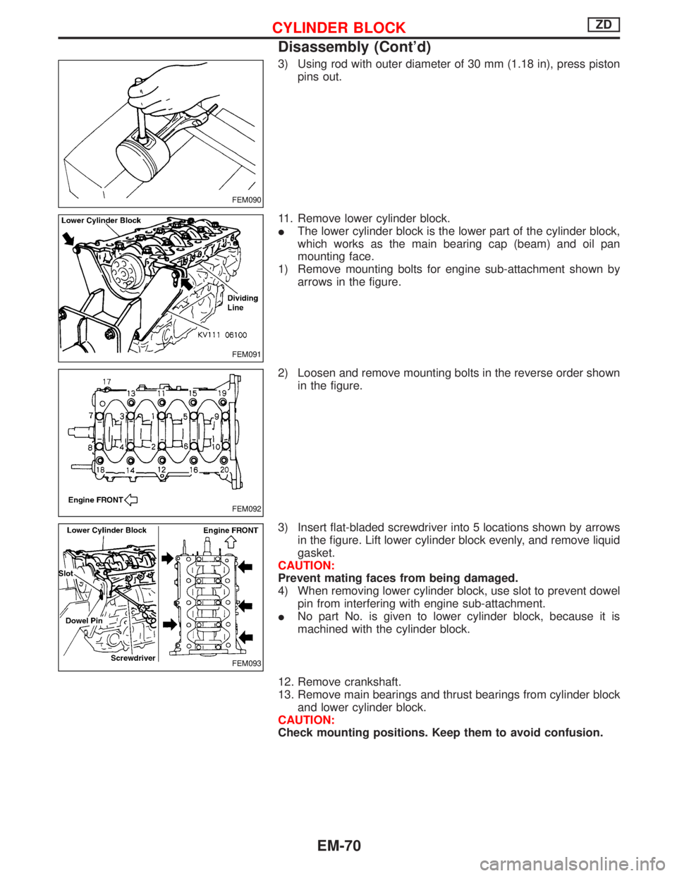
3) Using rod with outer diameter of 30 mm (1.18 in), press piston
pins out.
11. Remove lower cylinder block.
IThe lower cylinder block is the lower part of the cylinder block,
which works as the main bearing cap (beam) and oil pan
mounting face.
1) Remove mounting bolts for engine sub-attachment shown by
arrows in the figure.
2) Loosen and remove mounting bolts in the reverse order shown
in the figure.
3) Insert flat-bladed screwdriver into 5 locations shown by arrows
in the figure. Lift lower cylinder block evenly, and remove liquid
gasket.
CAUTION:
Prevent mating faces from being damaged.
4) When removing lower cylinder block, use slot to prevent dowel
pin from interfering with engine sub-attachment.
INo part No. is given to lower cylinder block, because it is
machined with the cylinder block.
12. Remove crankshaft.
13. Remove main bearings and thrust bearings from cylinder block
and lower cylinder block.
CAUTION:
Check mounting positions. Keep them to avoid confusion.
FEM090
FEM091
FEM092
FEM093
CYLINDER BLOCKZD
Disassembly (Cont'd)
EM-70